Final project · plant companion × holonomic mobile base
Forest Fairy
森之精灵
A mobile, AI-connected plant companion built around a live chili pepper plant (辣椒): it reads environmental and plant-side signals, surfaces chili status on the display, responds with motion and communication, and argues—quietly but seriously—that plants deserve their own form of dialogue, not a borrowed human medical chart.
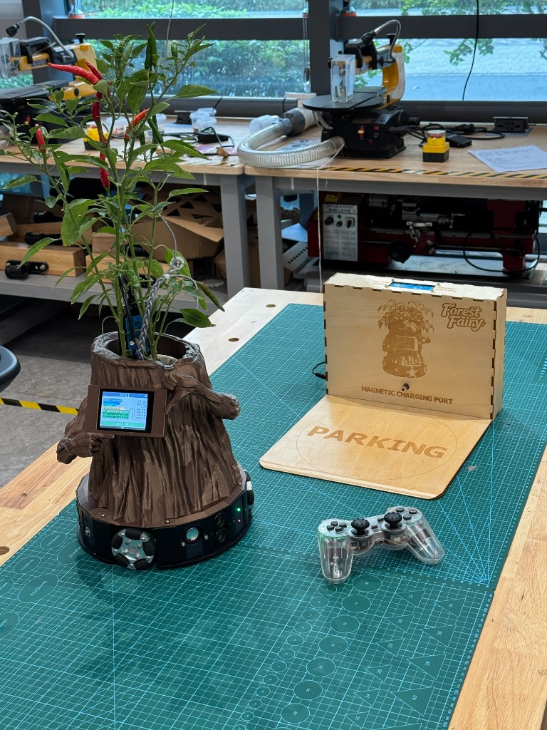
Final prototype
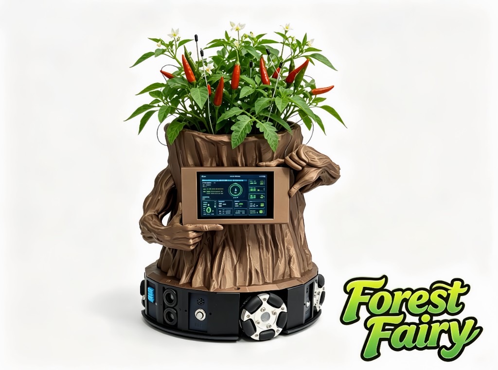
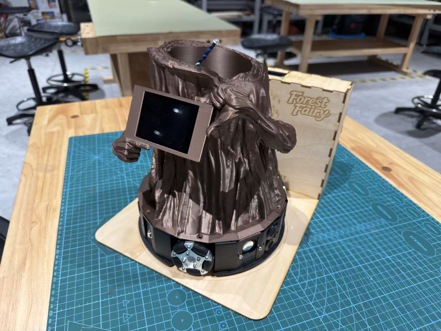
The completed Forest Fairy prototype brings the live chili plant, sensing shell, onboard display, holonomic base, and magnetic charging dock together for the final presentation.
- 1. Read environment Light, temperature, humidity, soil moisture, and nutrient-related channels on a steady cadence.
- 2. Read the chili plant Electrochemical / impedance traces on chili pepper leaves—compared to baselines, not human vital-sign metaphors.
- 3. Move & express 120° holonomic chassis for constrained repositioning; motion gated by safety and calibration state.
- 4. Communicate OLED and future dialogue/UI layers turn signals into honest prompts—with explicit unknowns.
What I am building hands-on
- Blender CAD for the planter + omni base interface, then FDM prints and assembly (Week 2, Week 5).
- Custom carrier PCB: ESP32-S3, Nanostat / AD5933 path, sensor buses, OLED FPC, motor headers (Week 6 rev. 2).
- Holonomic kit bring-up, sign conventions, and harness dress (Build process).
- Bench validation per subsystem before trusting the full stack (DHT, OLED, motors, Nanostat on leaves).
- Display/UI pipeline from Wokwi simulation to on-device OLED (Week 4 → Week 10).
- Final integration: one wiring story, flashing paths, and weekly pages as the lab notebook spine.
How I document completion
- CAD sources, print parameters, and assembly photos on linked week pages.
- KiCad schematic/PCB, fab outputs, soldering and electrical bring-up evidence (Week 6–Week 8).
- Live environment readouts on OLED (Week 10).
- Holonomic motion demos and kinematics notes (Build process).
- Plant-side captures with Mimiclaw-style theory vs. measurement comparison (Debug & test).
- Full integration video when the closed loop is stable—until then, honest weekly timelines.
Midterm review plan
For the Week 13 midterm review I froze the project at a planning checkpoint: the concept was clear enough to explain as a system, but the remaining work still needed to be sorted into buildable tasks. The brief asked for a system diagram, a remaining task list, a schedule, and review with local and global instructors.
+-------------------------+
| Live chili pepper plant |
| leaves, soil, pot space |
+------------+------------+
             |
             | physical signals
             v
+-------------------------+      +-------------------------+
| Sensing layer           |      | Environment layer       |
| Nanostat / AD5933 path  |      | light, temp, humidity,  |
| soil moisture / NPK     |      | context around plant    |
+------------+------------+      +------------+------------+
             |                                |
             | I2C / UART / ADC              | I2C / ADC
             +----------------+---------------+
                              v
                 +----------------------+
                 | ESP32-S3 system hub  |
                 | logging, calibration |
                 | safety state         |
                 +----------+-----------+
                            |
                            | structured plant state
          +-----------------+-----------------+
          |                 |                 |
          v                 v                 v
+-----------------+ +-----------------+ +-----------------+
| TFT / OLED UI   | | Voice / AI layer| | Motion layer    |
| status pages    | | cautious advice | | 3-wheel omni    |
| warnings        | | and dialogue    | | base + limits   |
+--------+--------+ +--------+--------+ +--------+--------+
         |                   |                   |
         +-------------------+-------------------+
                             v
                  +---------------------+
                  | Human care response |
                  | water, light, check |
                  | move, recharge      |
                  +---------------------+
Tasks still to complete after the review
- Mechanical: finish chassis-to-planter mounting, cable strain relief, and safe access to the plant.
- Electronics: populate and test the custom carrier board, confirm power rails, and label buses.
- Sensing: bring up temperature, humidity, light, soil, and plant-side acquisition with repeatable logs.
- Outputs: finish the local screen pages, voice prompts, and a basic motion demonstration.
- Integration: combine sensing, UI, and motion without letting one subsystem block the whole demo.
- Documentation: close missing weekly evidence, link source files, and keep failure notes visible.
Remaining schedule
| Window | Main work | Review target |
|---|---|---|
| Week 14 | Molding/casting parts for Forest Fairy details; test materials and finish. | One cast part documented with process photos and safety notes. |
| Week 15 | Interface and application layer: screen pages, touch/interaction flow, data display. | User can understand current plant status within about 30 seconds. |
| Week 16 | System integration: wiring, firmware merge, power, packaging, and bench demo. | End-to-end loop works once: sense → interpret → show / speak / move. |
| Week 18–20 | Applications, IP, final presentation, video, source archive, and final documentation pass. | Graduation-ready project page with proof, files, and a clear narrative. |
Instructor review log: local and global review meetings are recorded on Week 13. Replace the placeholder names/dates there with the exact meeting details after confirmation.
How I developed this website
I built this Fab Academy site in Cursor, mostly through vibe coding in the editor chat—working with ChatGPT 5.5 and Composer 2.5 to shape layout, typography, and styling instead of drafting every page from a blank file.
The home page started with three interlocking gear icons as the main visual. I then carried that look into the weekly assignment pages: background images and button styles so each week reads as part of one site, not a stack of disconnected HTML files.
When the structure felt stable, I pushed the repo to Fab Academy GitLab Pages so the live site stays tied to the same git history as my weekly documentation.
Final upload program: download the full firmware package.
Build roadmap
- 01 Holonomic base Kit assembly, wheel signs, safe motion before loading the planter (Build process).
- 02 Plant-side sensing Nanostat on leaves, baselines, Mimiclaw overlays (Week 6, §4).
- 03 PCB integration Populate boards, mate flex OLED, unify grounds and buses (Week 8).
- 04 UI & AI loop Sense → interpret → display/speech; networking as needed (Week 15+).
- 05 Full assembly Shell, plant, PCB, chassis, and cabling as one demonstrable robot (system integration documentation).
Every kind of life has its own grammar. This prototype is one step toward listening to the biology that has lived beside us, overlooked—turning guesswork into signal-driven collaboration without selling noise as drama.
References & archive
- Fab Academy Final Projects Archive — documentation structure.
- TidyBot++ — holonomic mobile-base reference.
- TidyBot++ (arXiv) — kinematics and control context.
final-project-weekly-plan.md— rolling week plan in-repo.- Weekly assignments — build and debug evidence trail.
- Adafruit SSD1306 · Adafruit AD5933 — display and impedance bring-up.
Documentation reports
Fab Academy–style reports below retain figures, parameters, and week links so someone else can follow the same build path. The overview above is the one-screen map; these sections are the reproducible depth.
1. Design report
Title and naming
Forest Fairy (森之精灵) is a prototype plant companion built on a potted chili pepper plant (辣椒) and an omnidirectional mobile base. The name is meant to feel woodland-adjacent and non-anthropocentric—not a cartoon pet that barks from a flowerpot.
Summary: role and intended use
The machine combines an omni-wheel mobile base, environment and substrate sensing, and an interpretable AI loop for dialogue and behavior. In use it should remind you to water or feed, seek better light within safe limits, show chili pepper status on the display in language tied to measured state rather than generic chit-chat, and—through IoT—coordinate with furniture and room systems so the space stays workable for both people and plants.
Design intent: motivation and trajectory
Forest Fairy closes one loop: a chili pepper plant (辣椒), a holonomic chassis, and an AI layer that ingests light, temperature, humidity, soil moisture, nutrient-related channels, and plant-side electrochemical / bioelectric responses. After calibration and analysis, it drives tangible feedback—water and fertilizer prompts, constrained autonomous motion, dialogue that matches measured chili status, and coordination with other home devices over the network.
What I am chasing is closer to an animal companion’s continuity of presence: sensing its own condition, making actionable requests, and sustaining a relationship over time—not pretending the plant is a dog, but describing another biology with honest uncertainty.
That motivation also answers low-friction care, the emotional load of living alone, and the “invisible roommate” problem in the next generation of smart homes. Technically, the point is to turn guesswork into signal-driven collaboration; emotionally, it is to admit that people can seriously care for plants, and that care deserves respect.
Why speak with plants, not only for them
We often treat houseplants as background, yet they keep responding—to light, water, air, nutrients, and touch—in chemistry and electrophysiology that were never invented for our convenience but still shape the room we share. When those responses stay invisible, care stays guesswork. When they are visible and read honestly, you gain both practical value (fewer dead plants) and a quiet emotional value: acknowledging another life in the room. I am not claiming plants “think like people”; I am claiming they exist on their own terms and deserve vocabulary that fits.
Watering, fertilizing, rotating pots, dusting leaves, worrying about frost or scorch—these already parallel how we feed, groom, and shelter cats and dogs. The structural gap is often that plants lack a legible channel back, so affection thins into intermittence. This prototype works more like a mouthpiece, translating physical and physiological state into language and cues humans can follow, with clear limits: no exaggeration, no fabrication.
The core monitoring dimensions are water, light, nutrients, and context. They are the substrate of photosynthesis, growth, and recovery—not metaphors. For the plant, the trajectory is species-specific, not a human clinic transcript. Electrochemical or impedance traces shift with sun and shade, before and after watering, and with air chemistry, which is why interpretation leans on change against the plant’s own recent baseline instead of a single textbook threshold.
Biological systems fluctuate; repeated readings on one plant can wobble without a “message.” After calibration and long comparison, variation that still fails to line up with care events is treated as noise or stochastic background, not secret poetry. The goal is a grounded interface to another biology.
Heart rate, blood pressure, facial expression, and human speech are signatures of human bodies and cultures. Stomatal behavior, osmotic regulation, photosynthetic rhythm, and electrochemical response are a different grammar. Forcing plants to prove distress only in human-shaped signals misreads them and blocks learning. Sensors and models should be judged by how well they fit this organism, not how closely they mimic a wristband.
I want the relationship between people and plants to move from “keep it alive” toward a broader sense of dialogue—trends, needs, limits, shared rhythms. Energy, materials, and symbiotic futures stay open questions. This prototype is a domestic-scale, hands-on first step on the path of talking with life, not only about it.
Figures: concept art, references, and kinematics
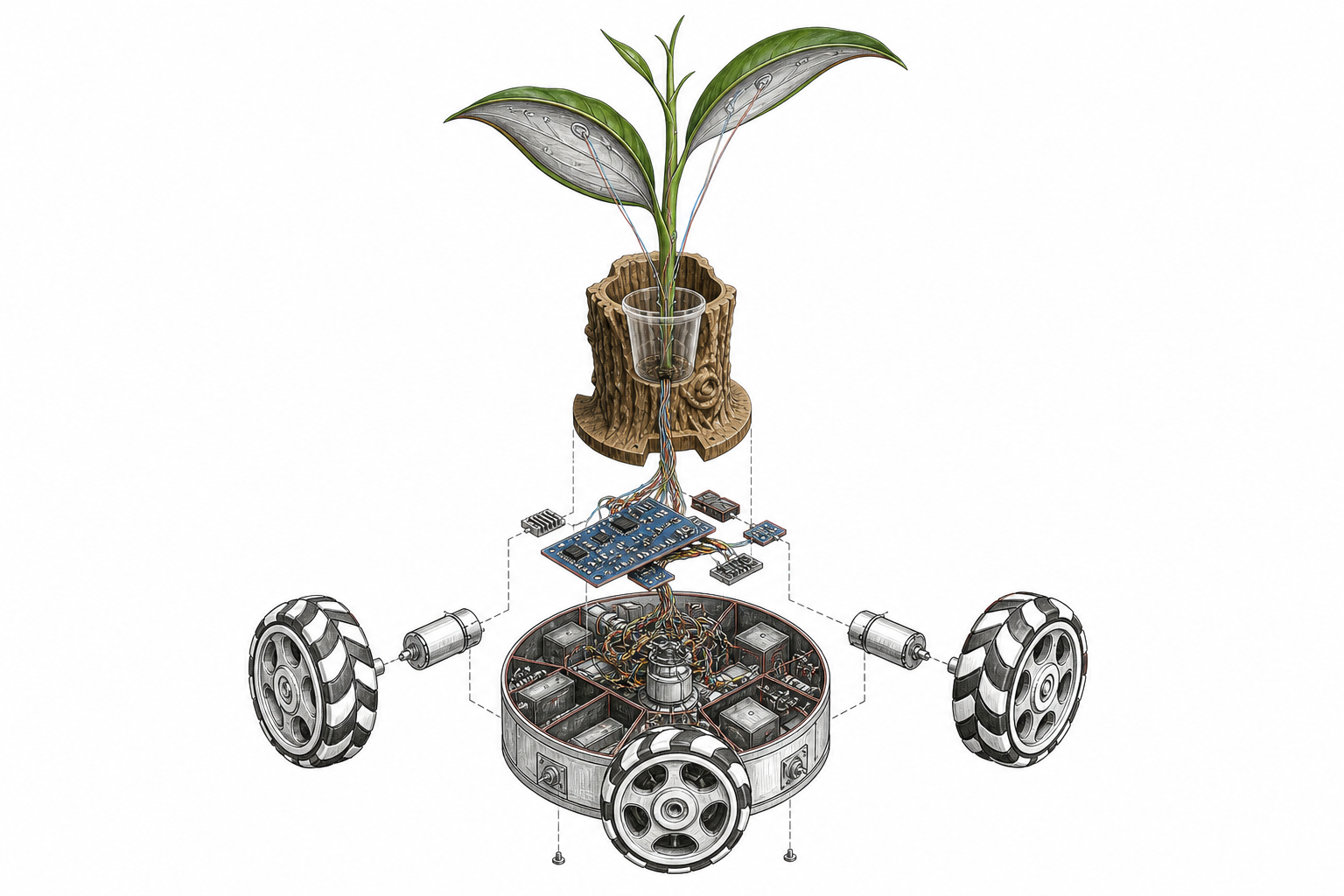
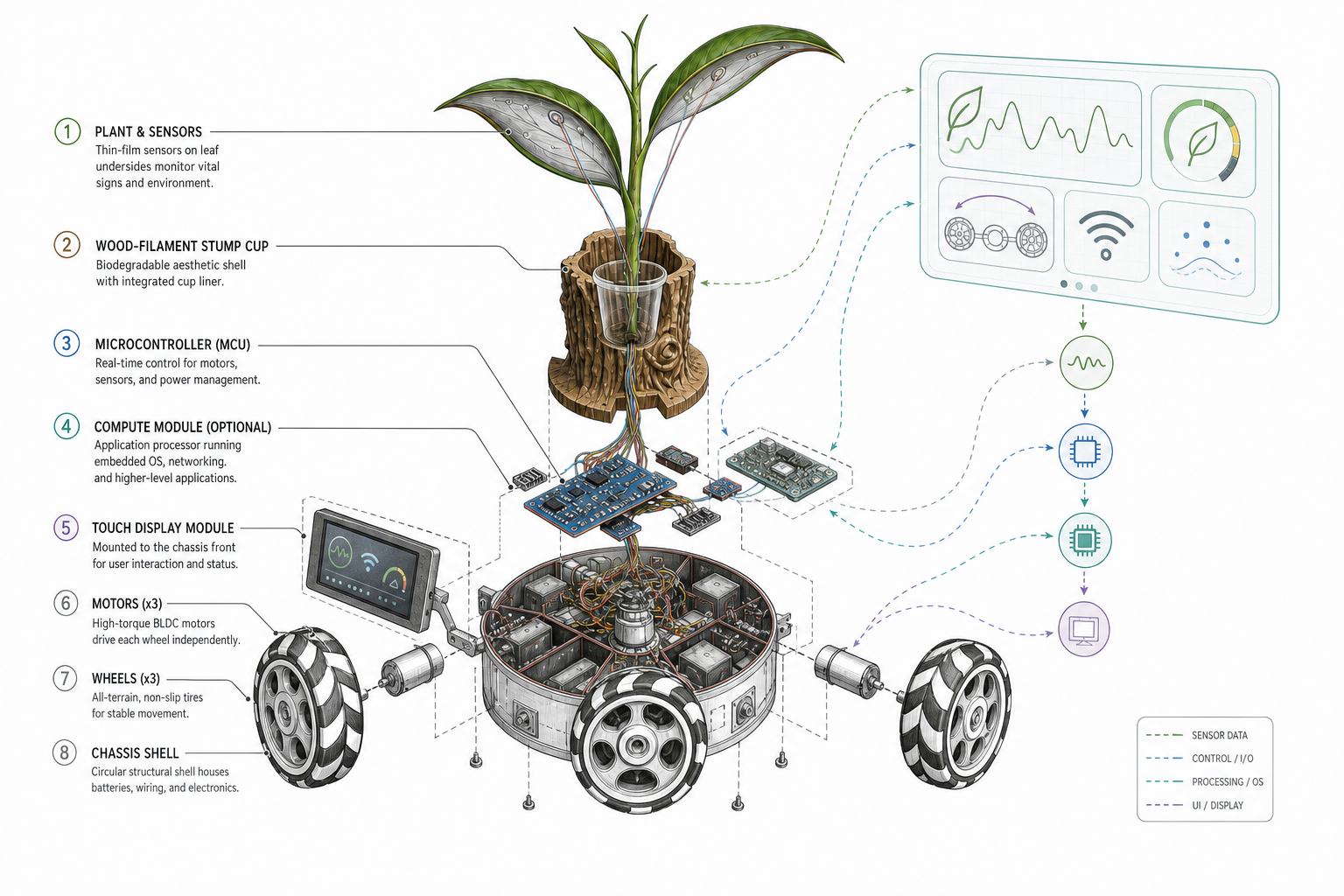
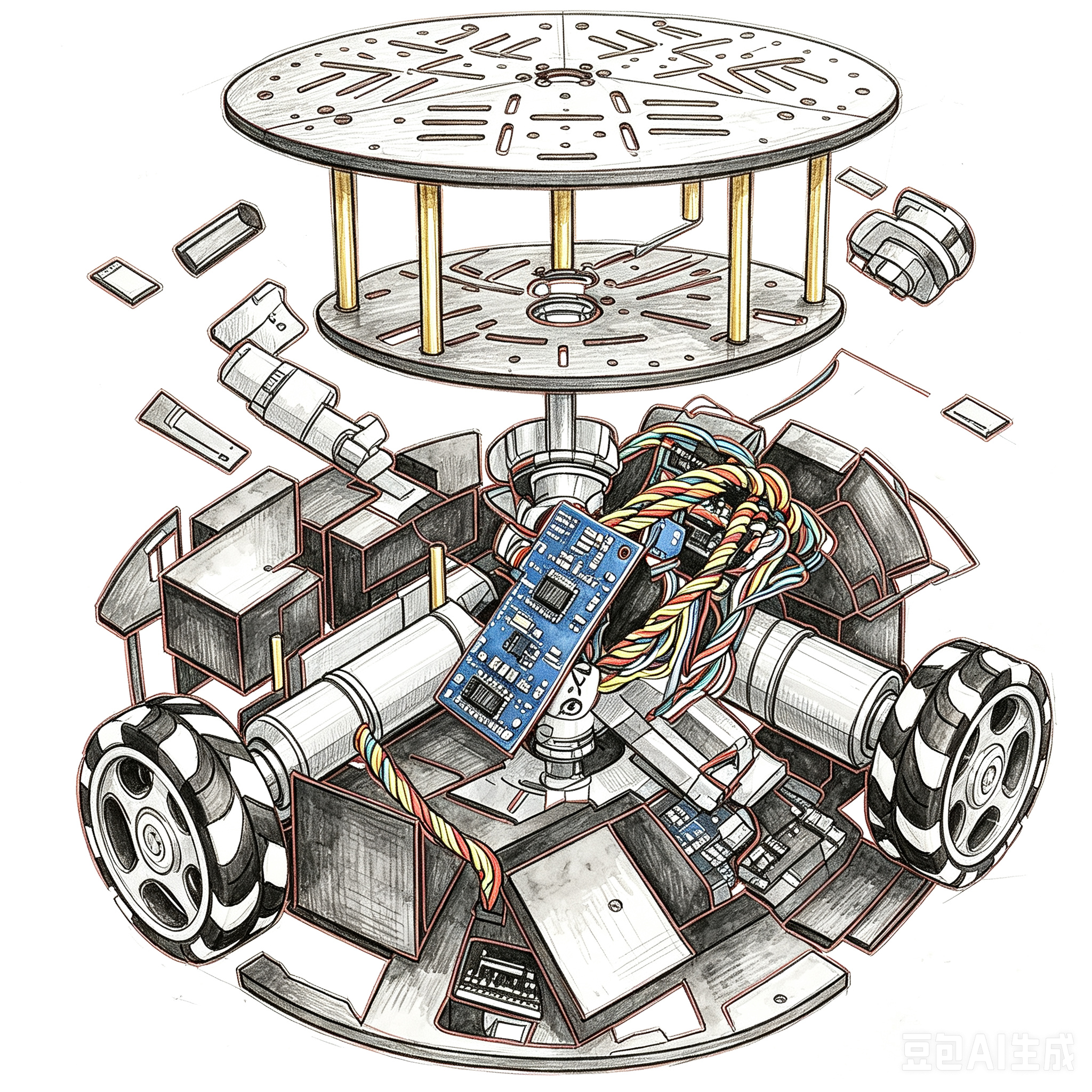
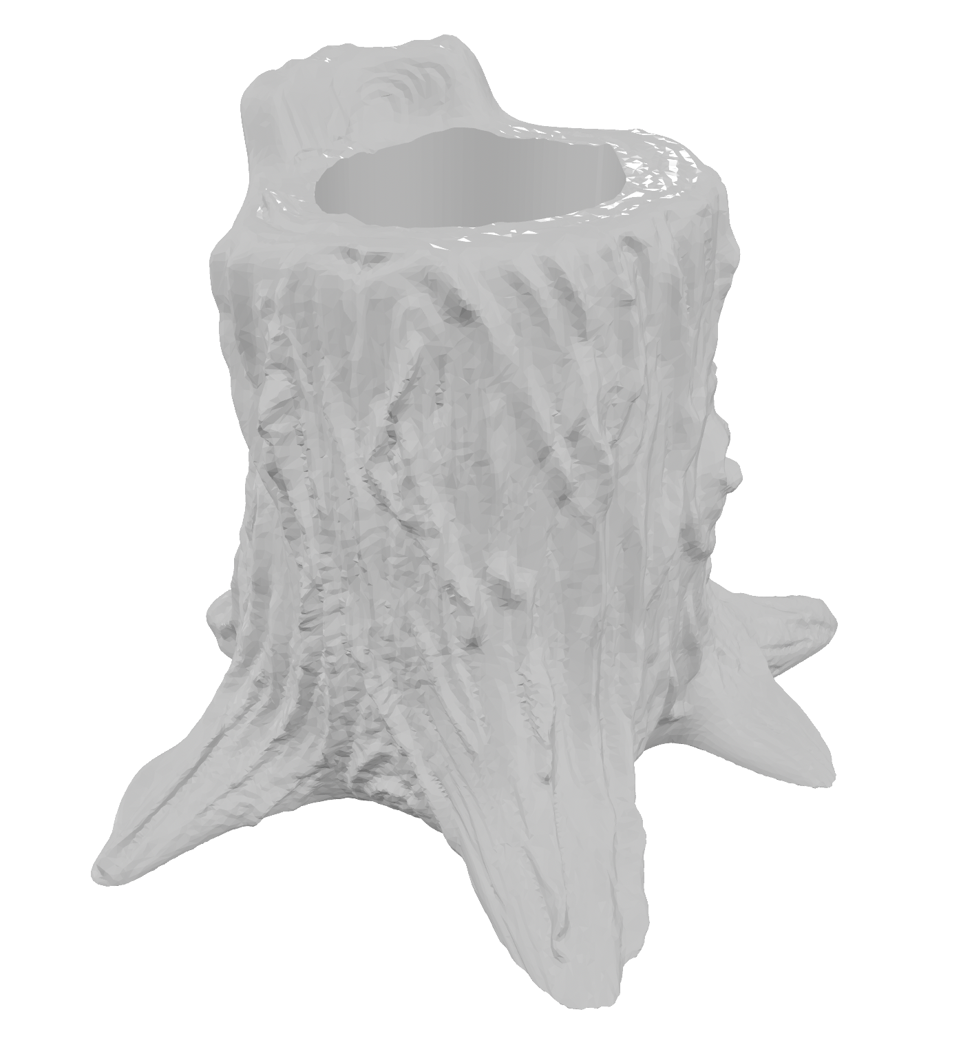
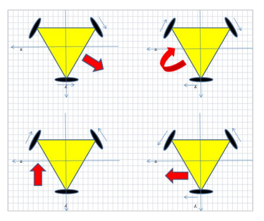
Conceptually the robot stacks three layers: planter and sensing volume, omnidirectional mobile base, and edge compute plus connectivity. Figures below combine AI-generated product renders—a quick readable “finish line” picture for the page—with weekly documentation: digital sketches, kit references, and kinematics notes.
Finished visualization (AI)
I generated two reference images so visitors can grasp the intended presence of the assembled companion before wading through CAD and bench photos; they illustrate mood and layering, not shop-floor evidence.
Milestones (planning)
- Milestone 1 — Holonomic base, sensing shell, and safe motion (e.g. Build process, Week 8).
- Milestone 2 — Reliable plant-side acquisition and baseline models (e.g. Week 6, Week 9).
- Milestone 3 — Integrated AI loop: signals → interpretation → UI / speech / motion (e.g. Week 10, Week 15).
Week-by-week planning also lives in
final-project-weekly-plan.md. Build and debug evidence is threaded through the
weekly assignment pages.
2. Hardware report
Build process — how everything came together
The work moved from a rolling chassis through a decorated body and a readable display, then through sensors and MCUs tested in isolation, and finally to one wiring harness and one coherent firmware story. Every week page exists even when the narrative is thin—follow the links for whatever proof is online today. Index: all weeks · 1 · 2 · 3 · 4 · 5 · 6 · 7 · 8 · 9 · 10 · 11 · 12 · 13 · 14 · 15 · 16 · 18 · 19 · 20.
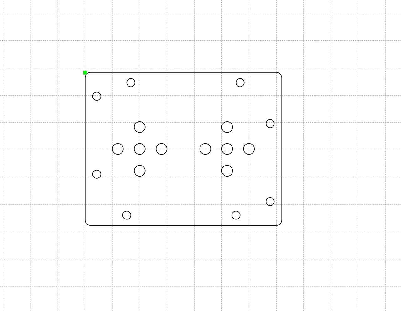
1) Chassis first — purchased kit, then adaptation. I began with a commercial three-wheel omnidirectional mobile-base kit (compact holonomic layout with omnidirectional rollers—often sold beside Mecanum-style educational rovers, even though this geometry is three-wheel). Unboxing, assembly order, and the kinematics sketch are documented under Build process. The kit supplied geared motors, wheel pods, a controller board, power, and a handset. For Forest Fairy I treated that stack as a known-good motion substrate, then modified it: mount points and cable exits for the upper body, strain relief for encoder leads near the wheels, and later the electrical interface to the custom carrier instead of only the stock harness. Bringing the base up first kept debug separable—if the platform could not roll safely, nothing above it mattered.
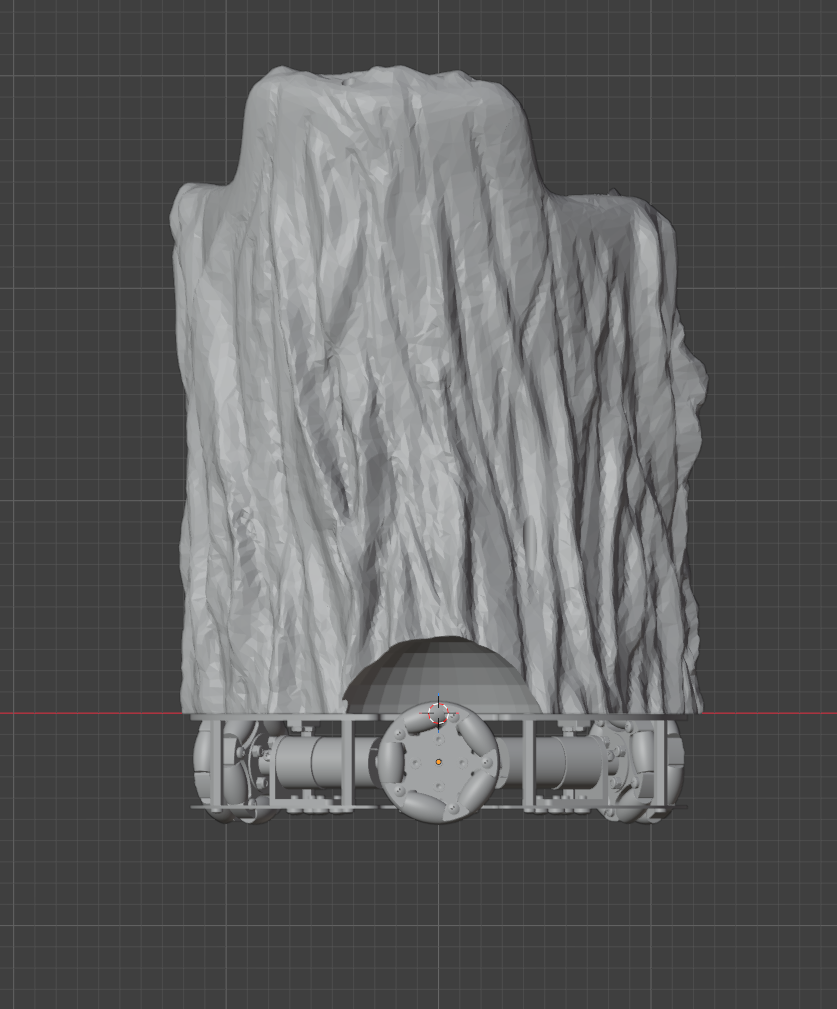
2) 3D modeling, printing, and a molded “Forest Fairy” motif. In Blender I modeled the organic planter and its interface to the wheel plate ( Week 2 — individual), exported for FDM, and ran the long prints that lock the silhouette to the chassis ( Week 5 — individual). For the spirit artwork I produced a mold and cast a physical accent so the robot is not only flat plastic; process and safety context sit under Week 14 — group and Week 14 — individual.
3) Display stack and UI design. Alongside mechanics I fixed how a human reads chili pepper status on screen: which display (flex / OLED), which canvas size, and how status screens map to the sense → interpret pipeline. The carrier PCB narrative includes the display FPC footprint and breakout header ( Week 6, especially revision 2 — Nanostat + ESP32-S3). On the bench I moved from early “sensor to pixels” simulation ( Week 4 — Wokwi LCD) to real OLED bring-up and layout passes on the XIAO ( Week 10 — individual). Tooling notes for anything beyond bare Arduino graphs sit with the interface-programming comparison ( Week 15 — group).
4) Subsystem bench tests before trusting the stack. I validated one block at a time. Nanostat: vendor documentation plus the six-pad / UART plan in the carrier story ( Week 6 — revision 2). Temperature and humidity: breadboard libraries, I²C checks, and display plumbing ( Week 10, with earlier serial context in Week 9). Mimiclaw: for now logged alongside the input-device week ( Week 9 — placeholder until a dedicated section grows). Drive motors: polarity, encoders, and load tied to the chassis week ( Build process).
5) Final integration — wiring, PCB marriage, and flashing. Harness layout, populating boards from the fab, mating flex to the screen, tying Nanostat and sensor buses to a single ground reference, and flashing each MCU along proven paths: Week 8 — individual (boards, assembly, orders) and Week 6. The objective is one reproducible electrical story that matches the photo trail on those pages—even when captions are still incomplete.
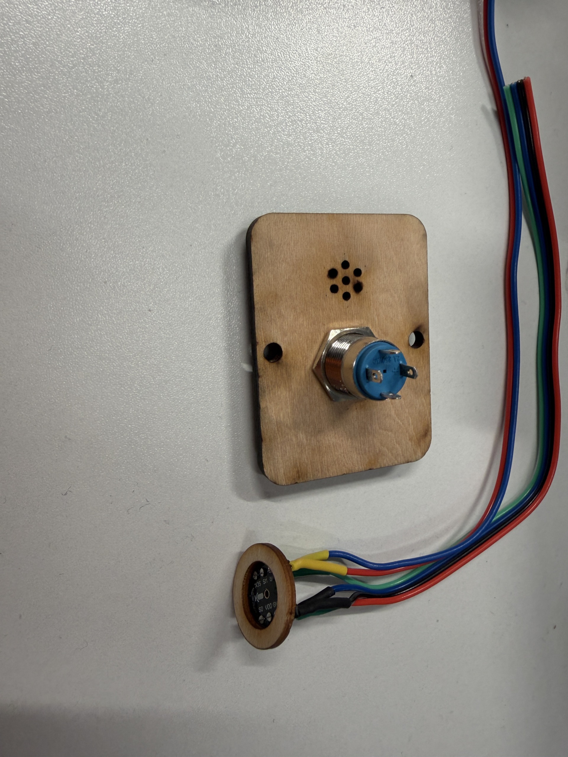
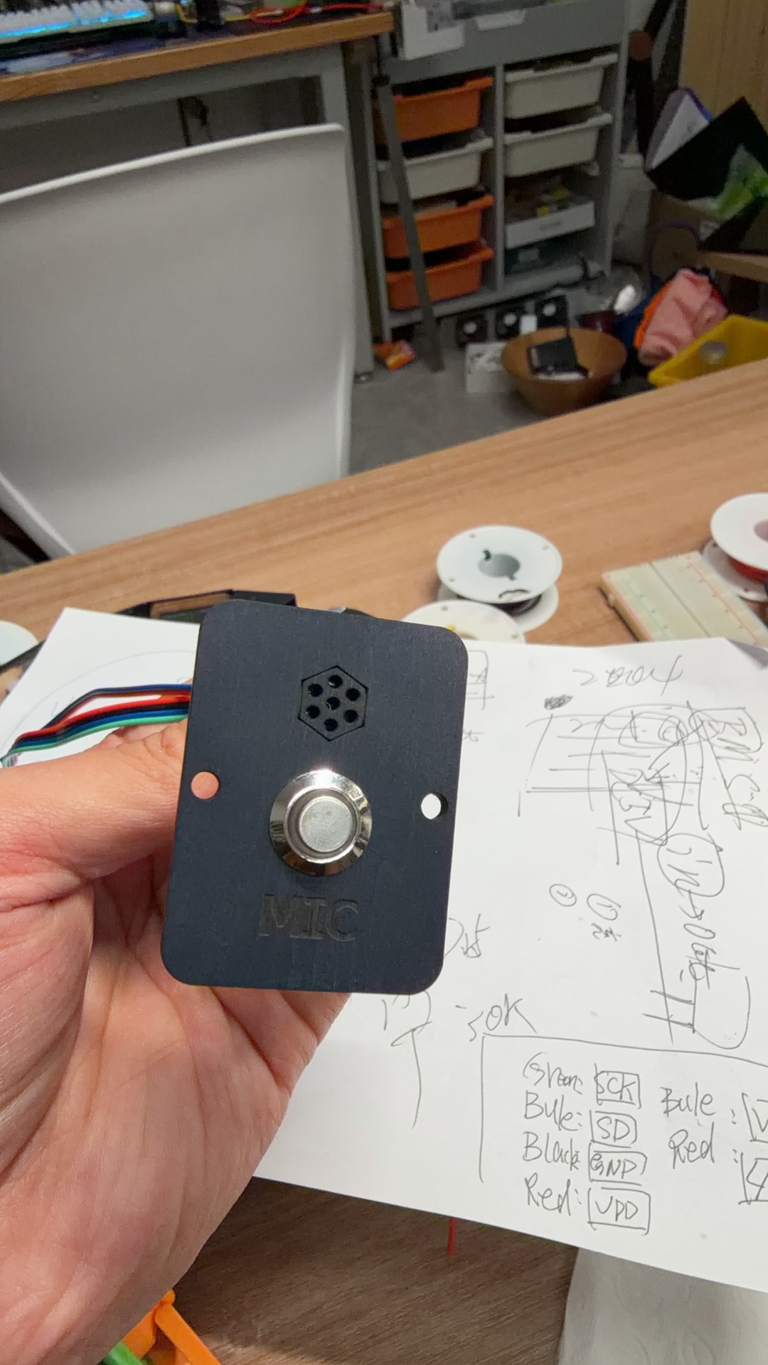
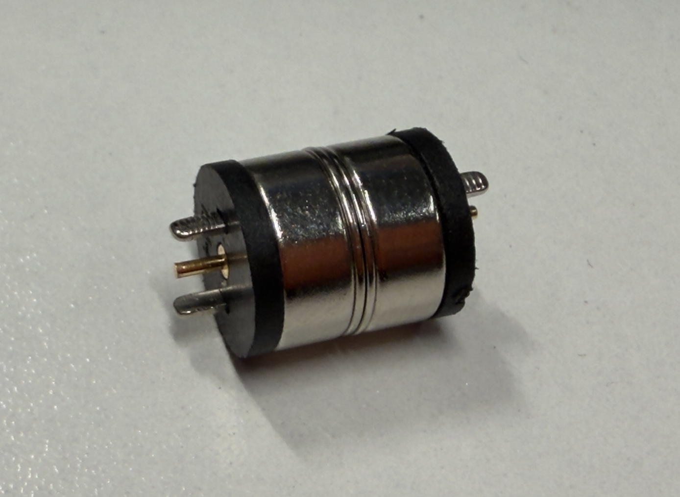
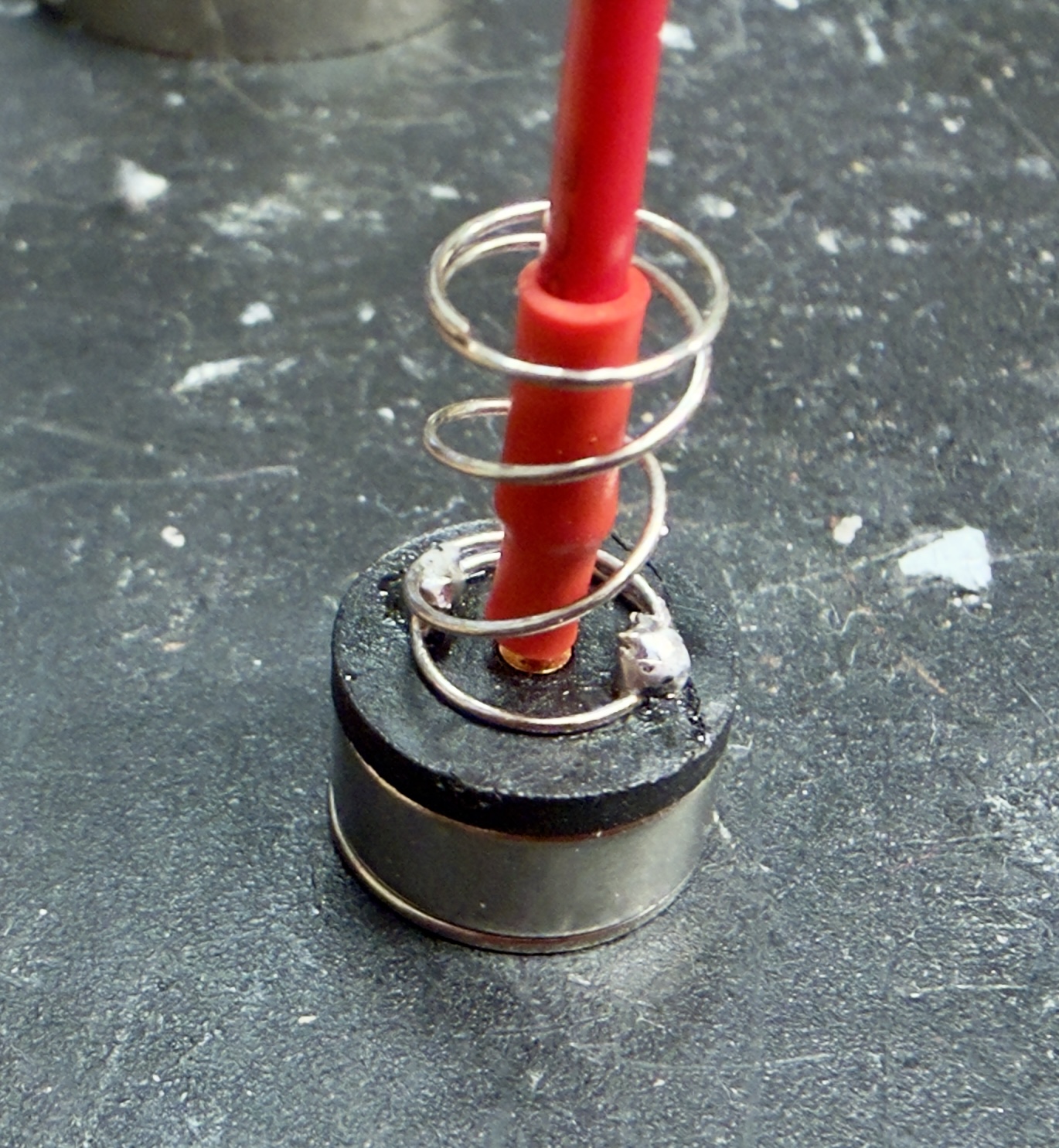
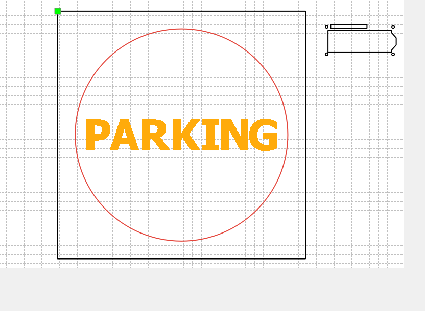
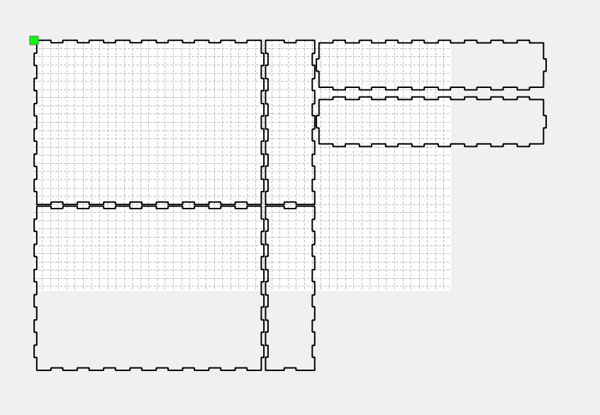
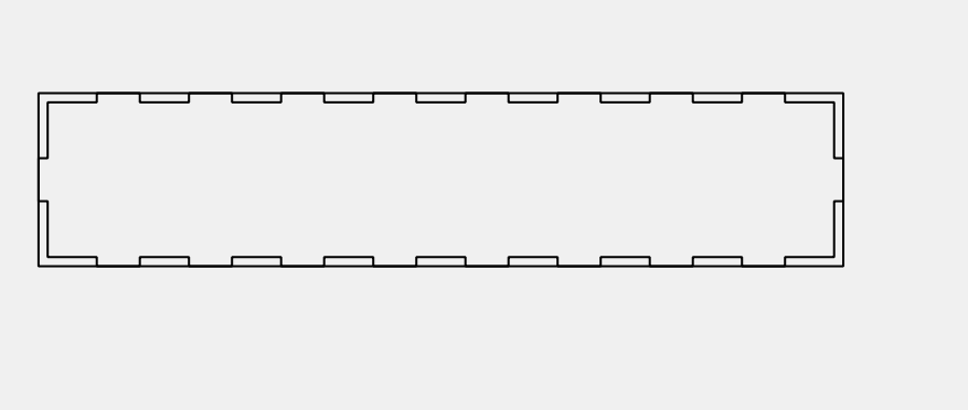
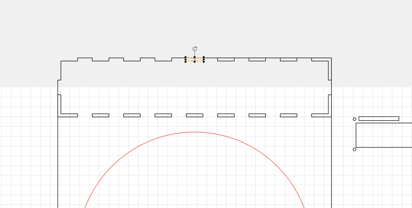
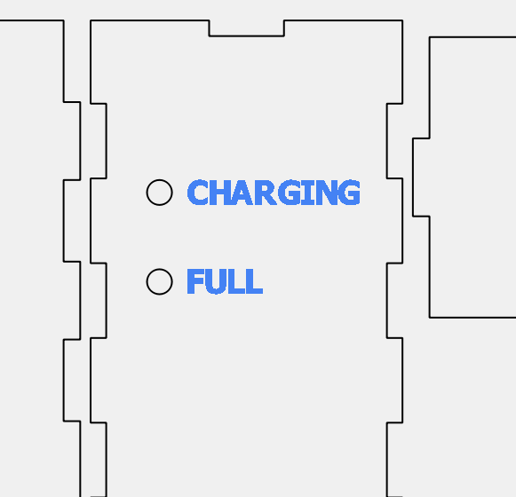
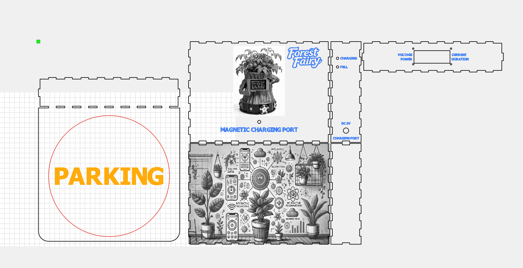
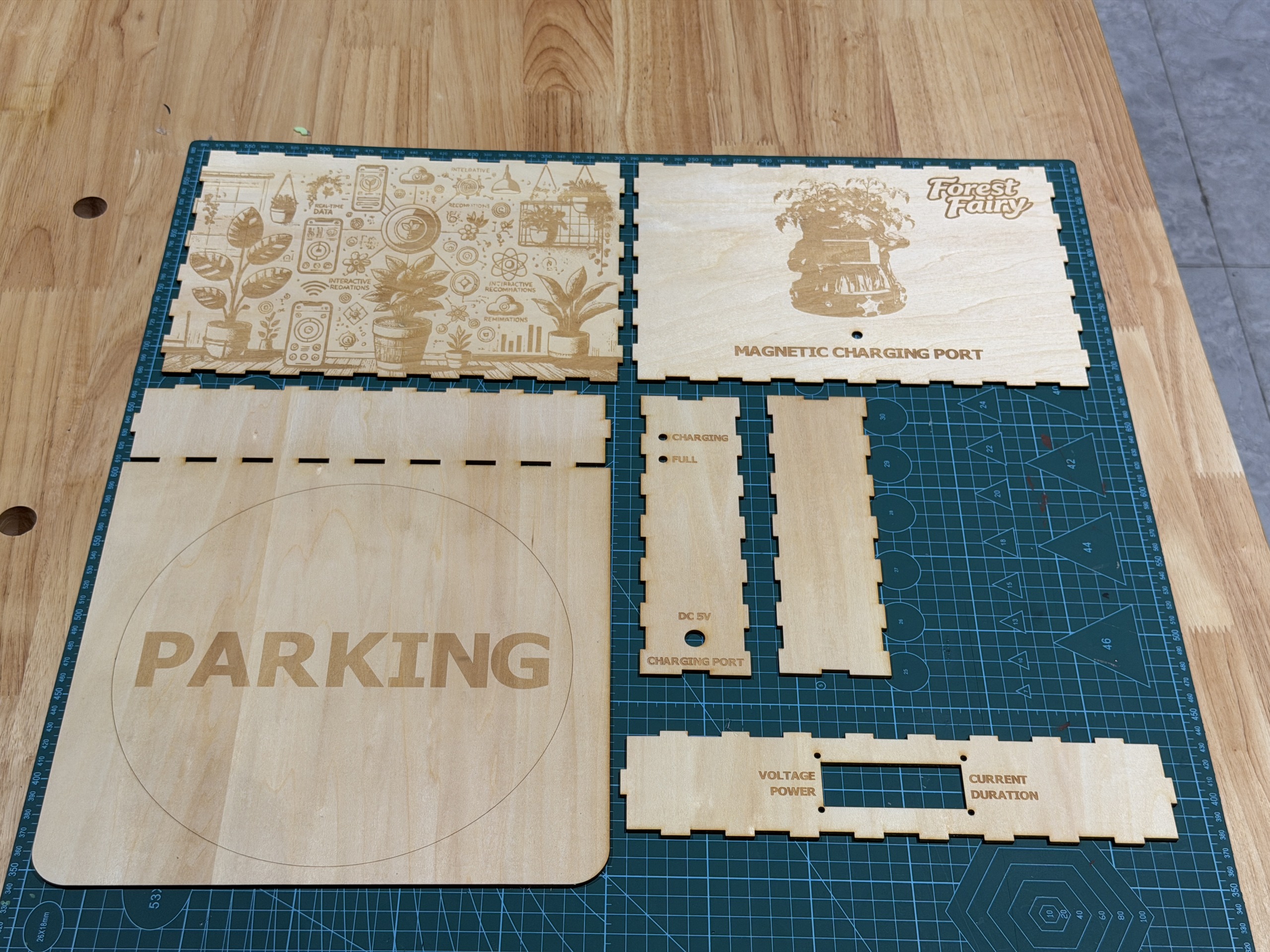
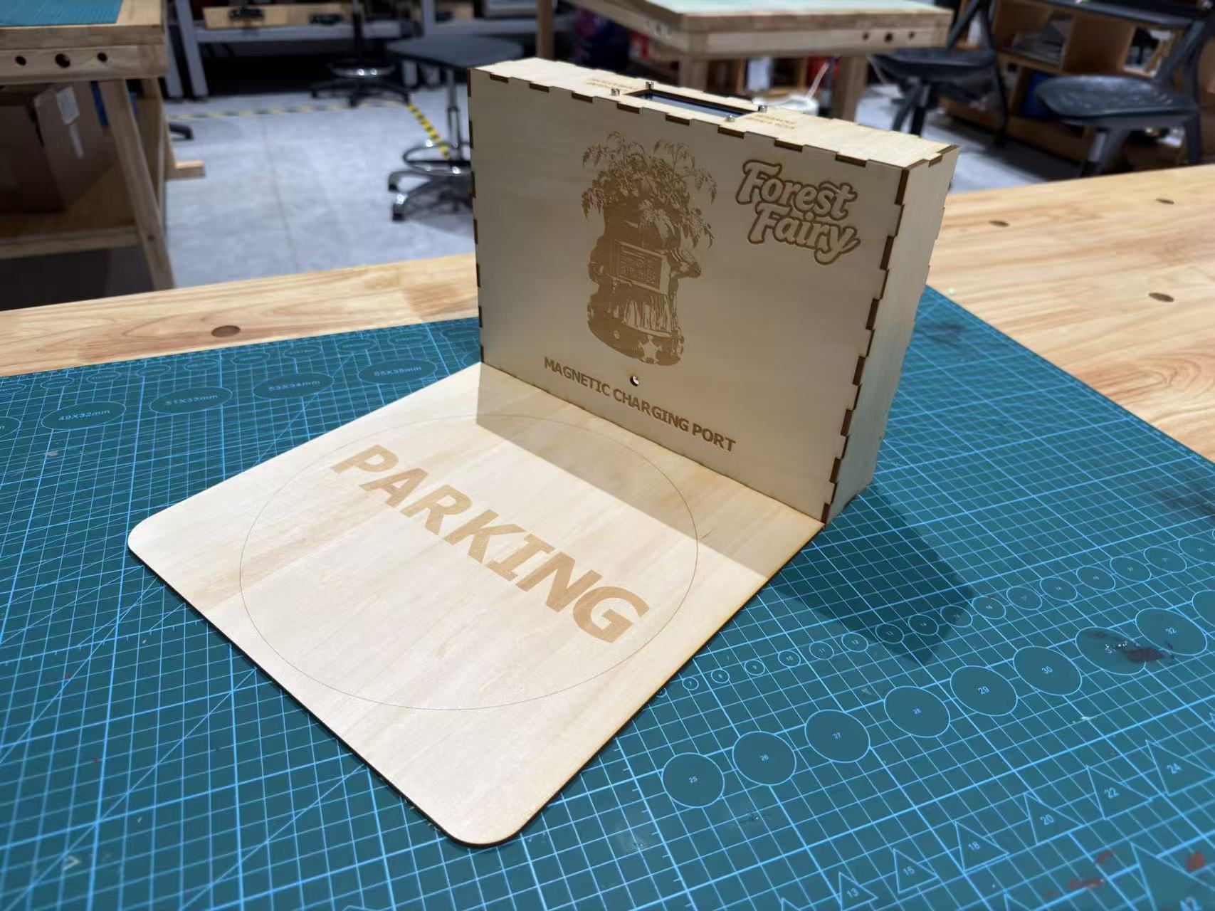
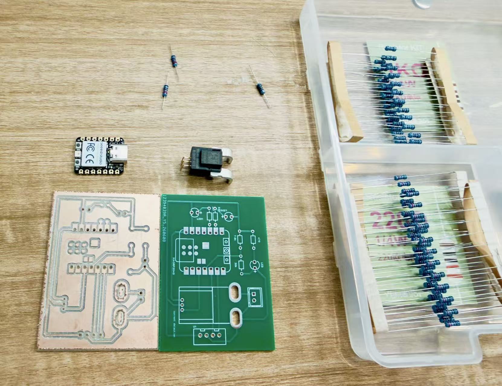
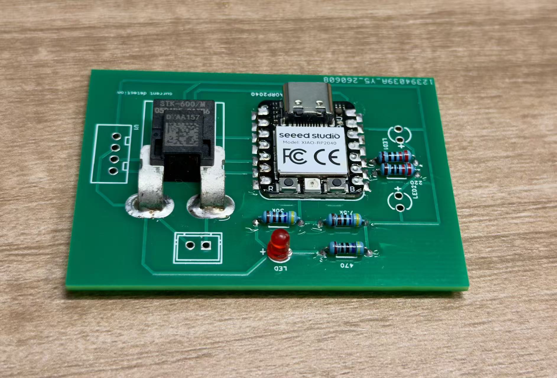
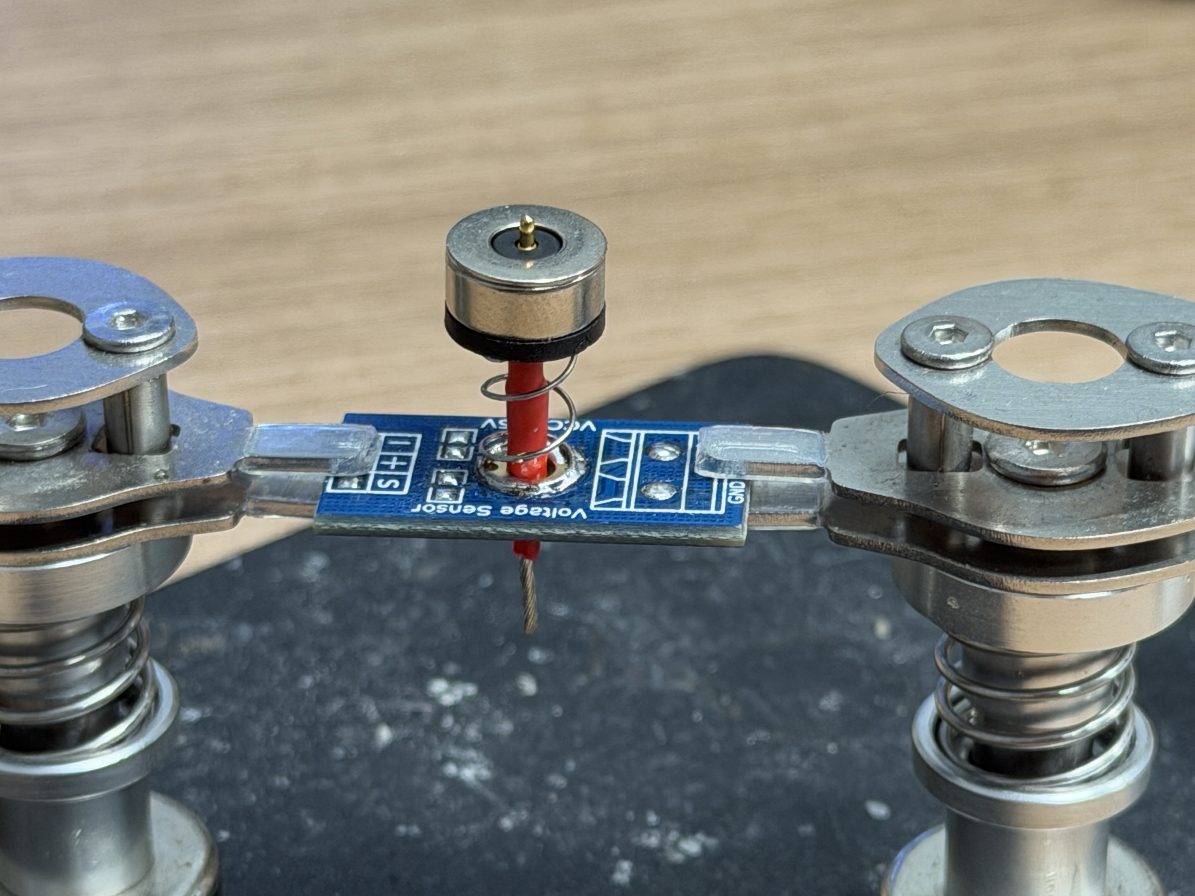
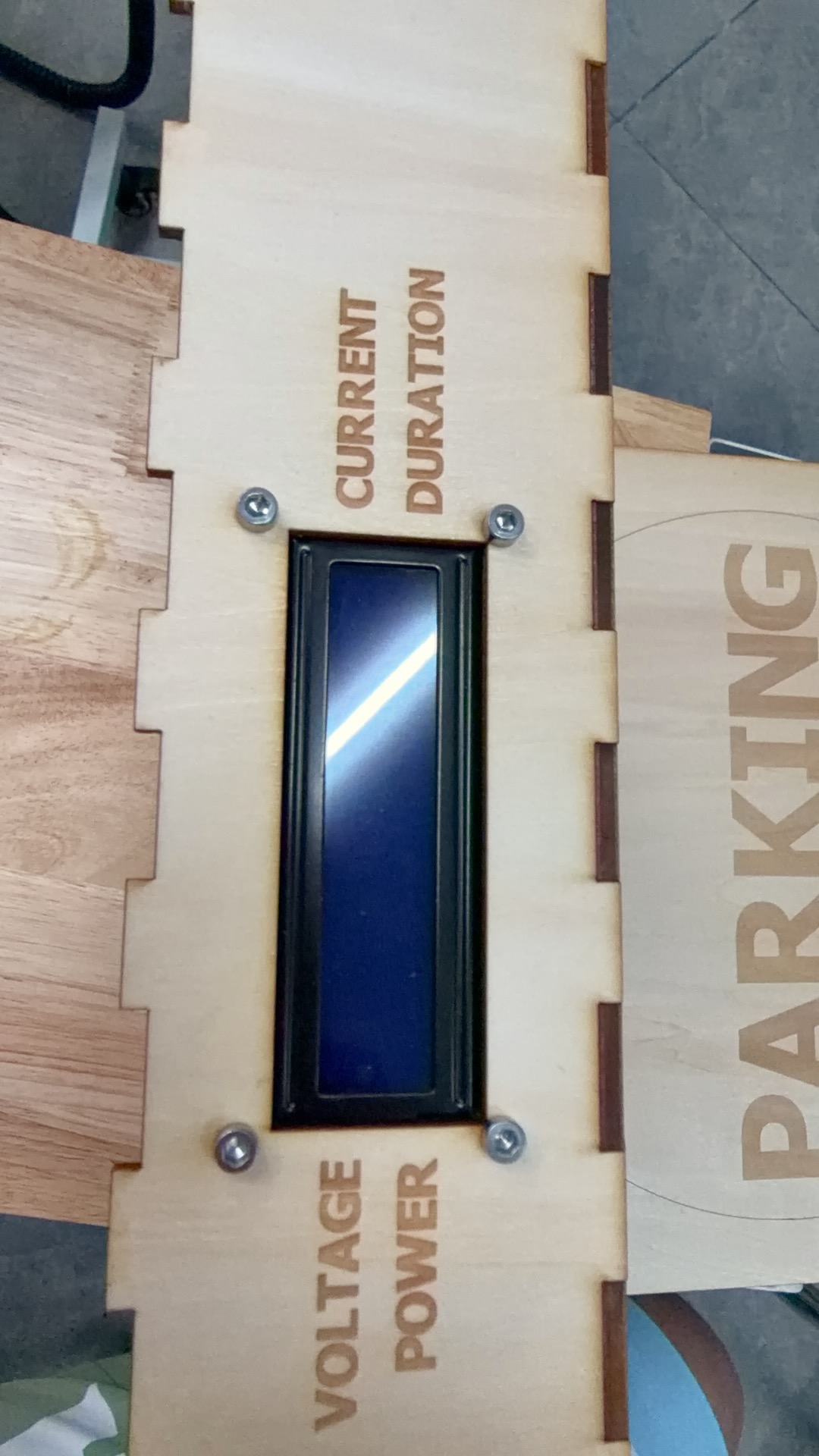
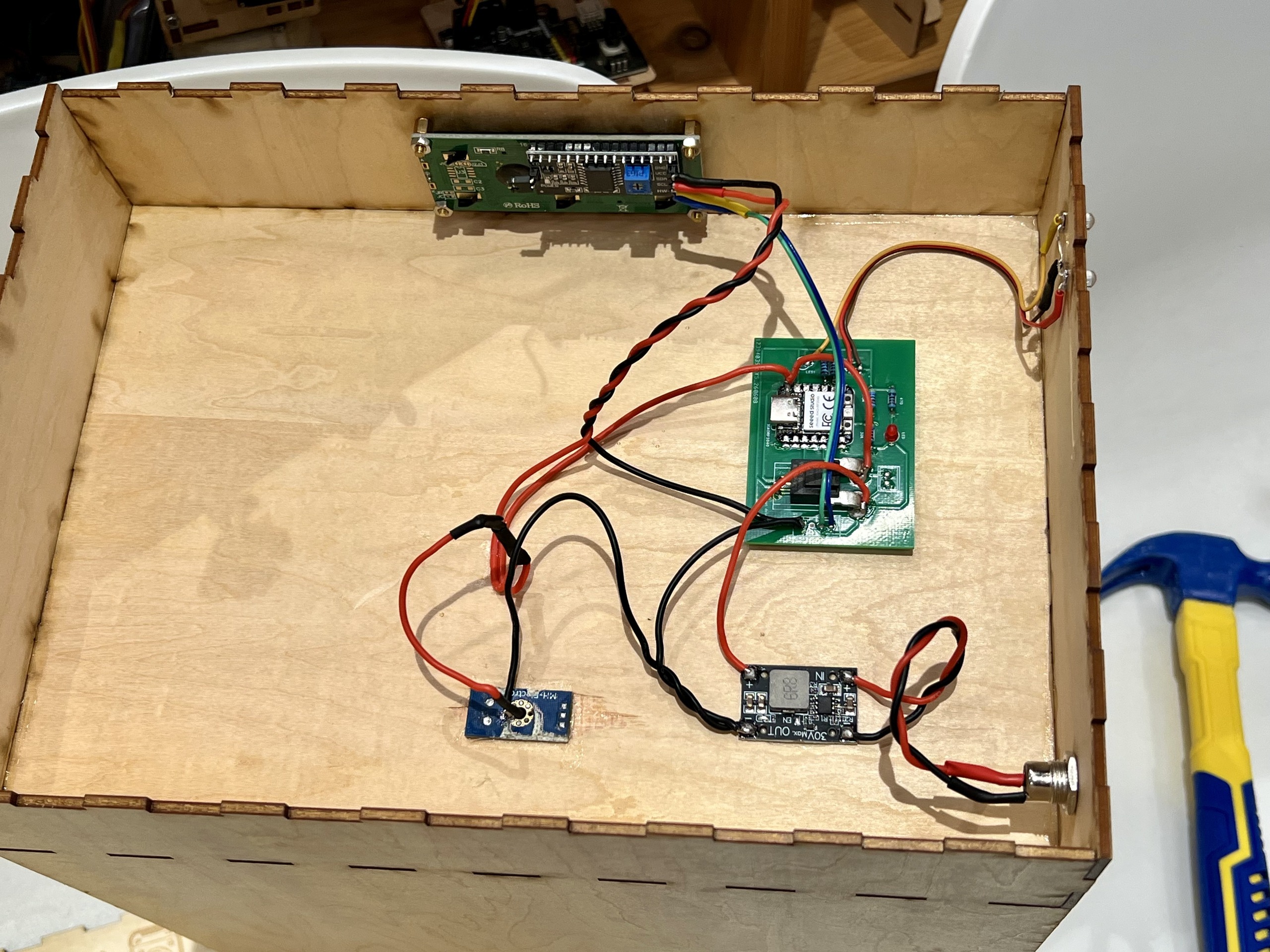
The Forest Fairy charging dock (充电桩)—magnetic contacts, DC input, status LEDs, wake button, mic, and LCD1602 top panel—is documented step-by-step under Charging dock photos.
Holonomic base — integration chronology (photos & video)
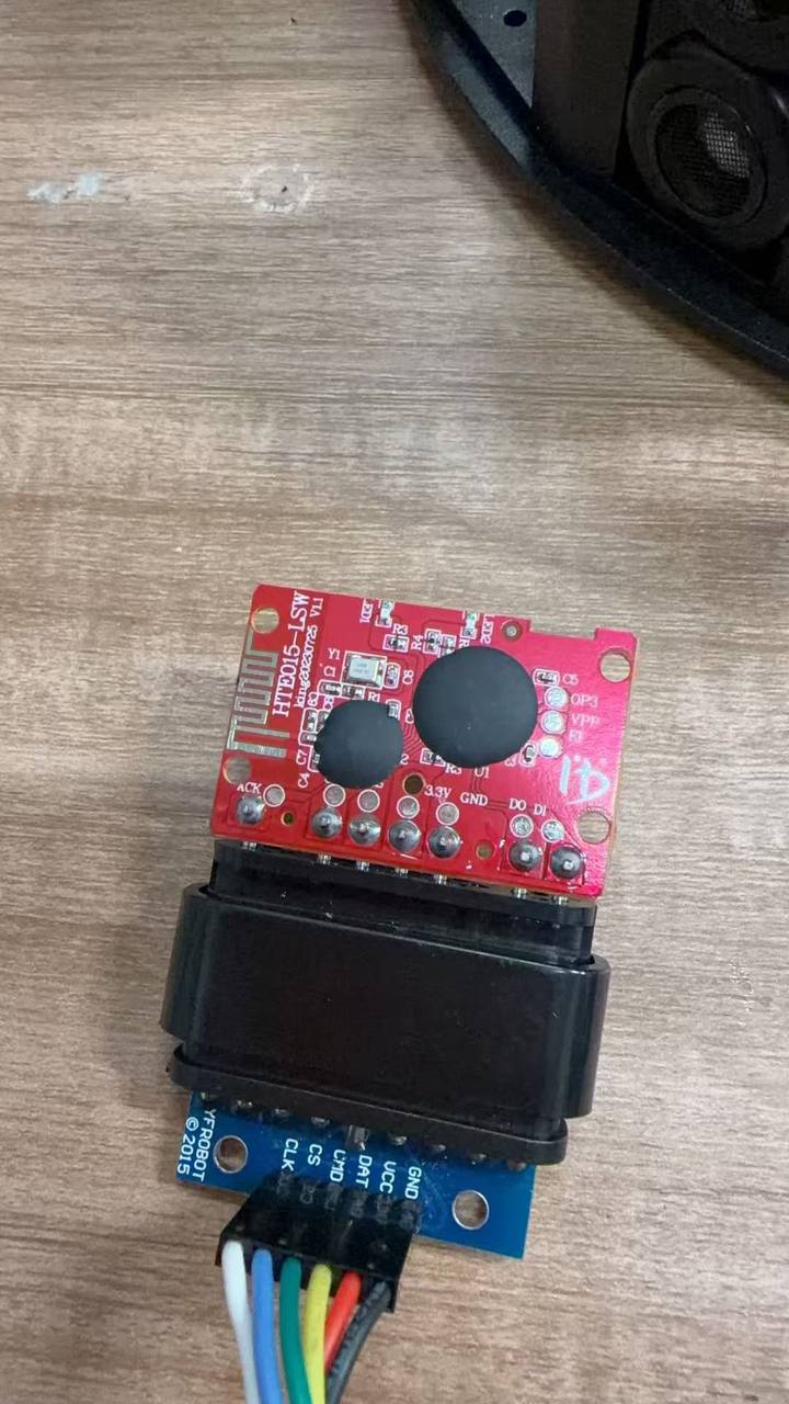
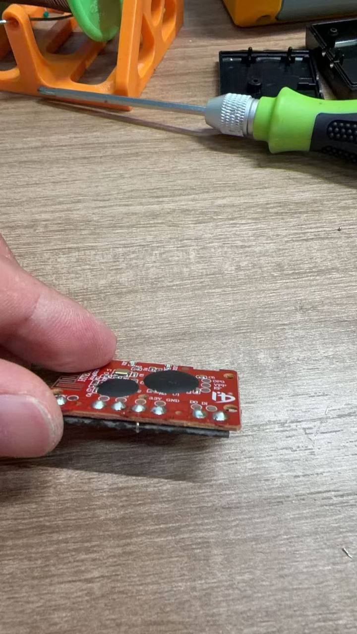
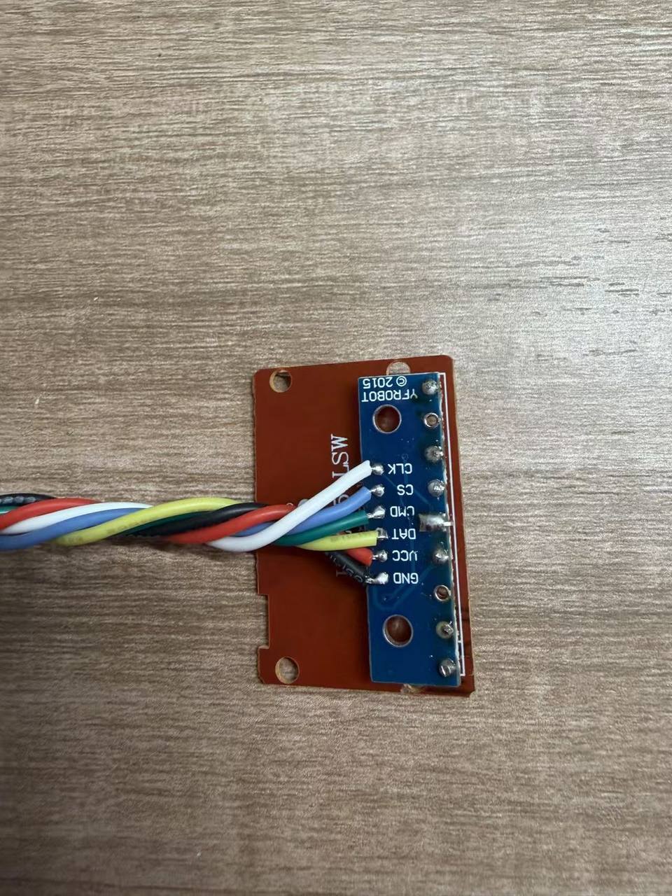
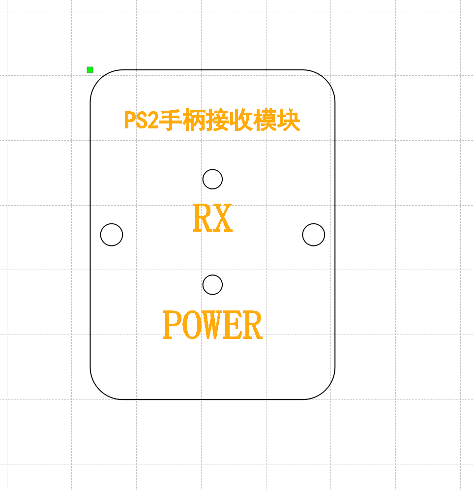
Below is the on-bench build log for adapting the holonomic kit—numbered 1–22 in build order. Images are shown two per row in a 16∶9 landscape frame; captions summarise each step in English.
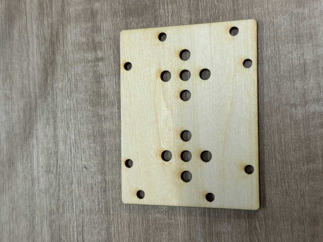
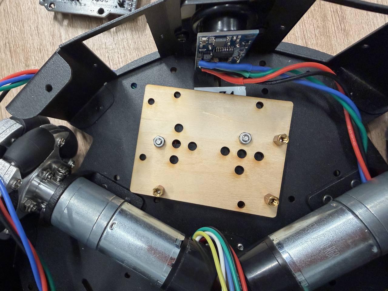
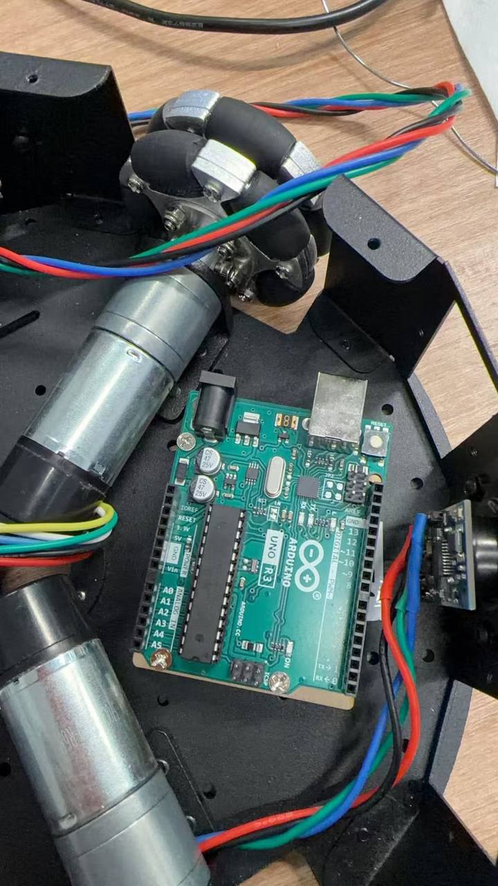
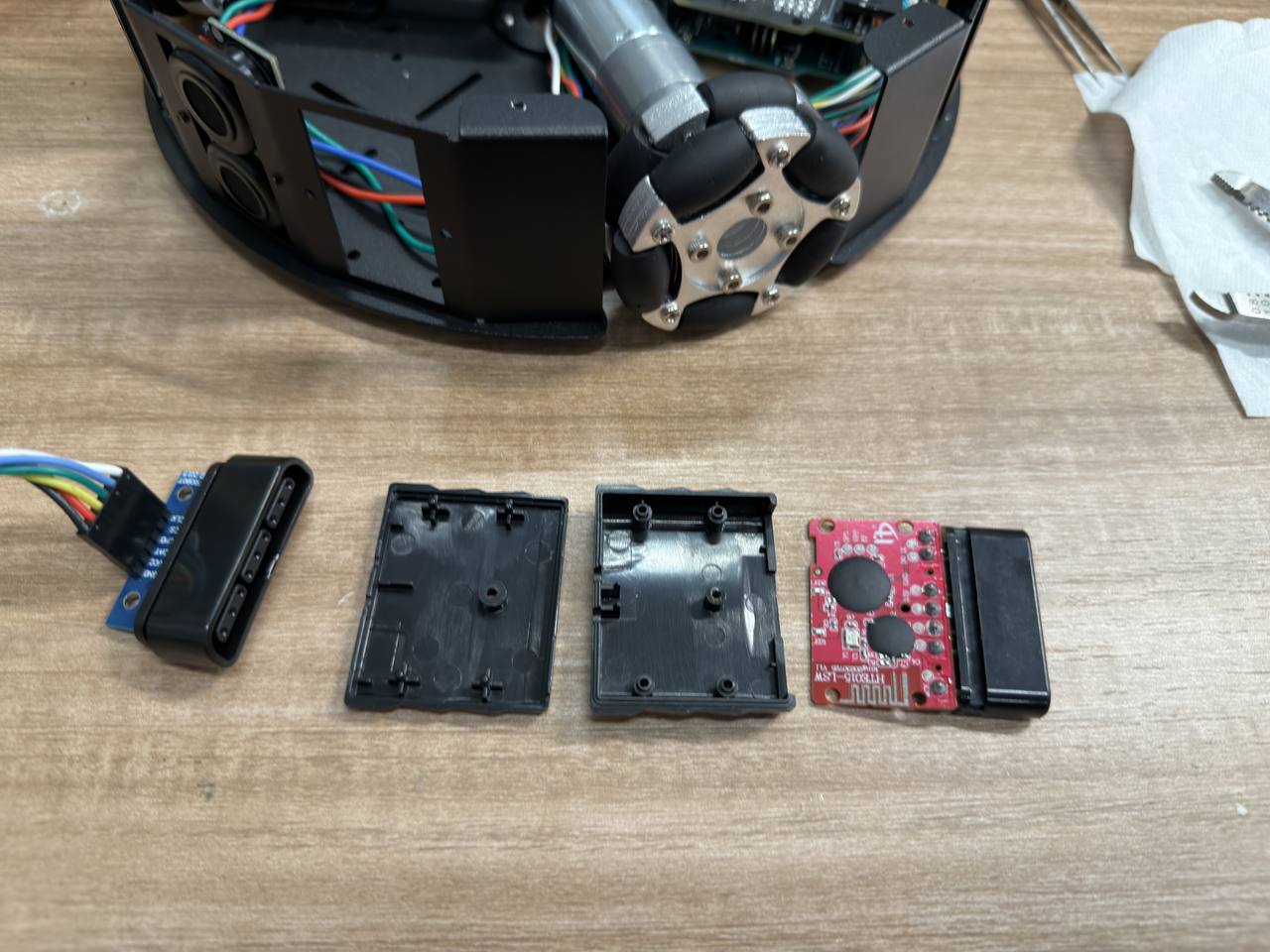
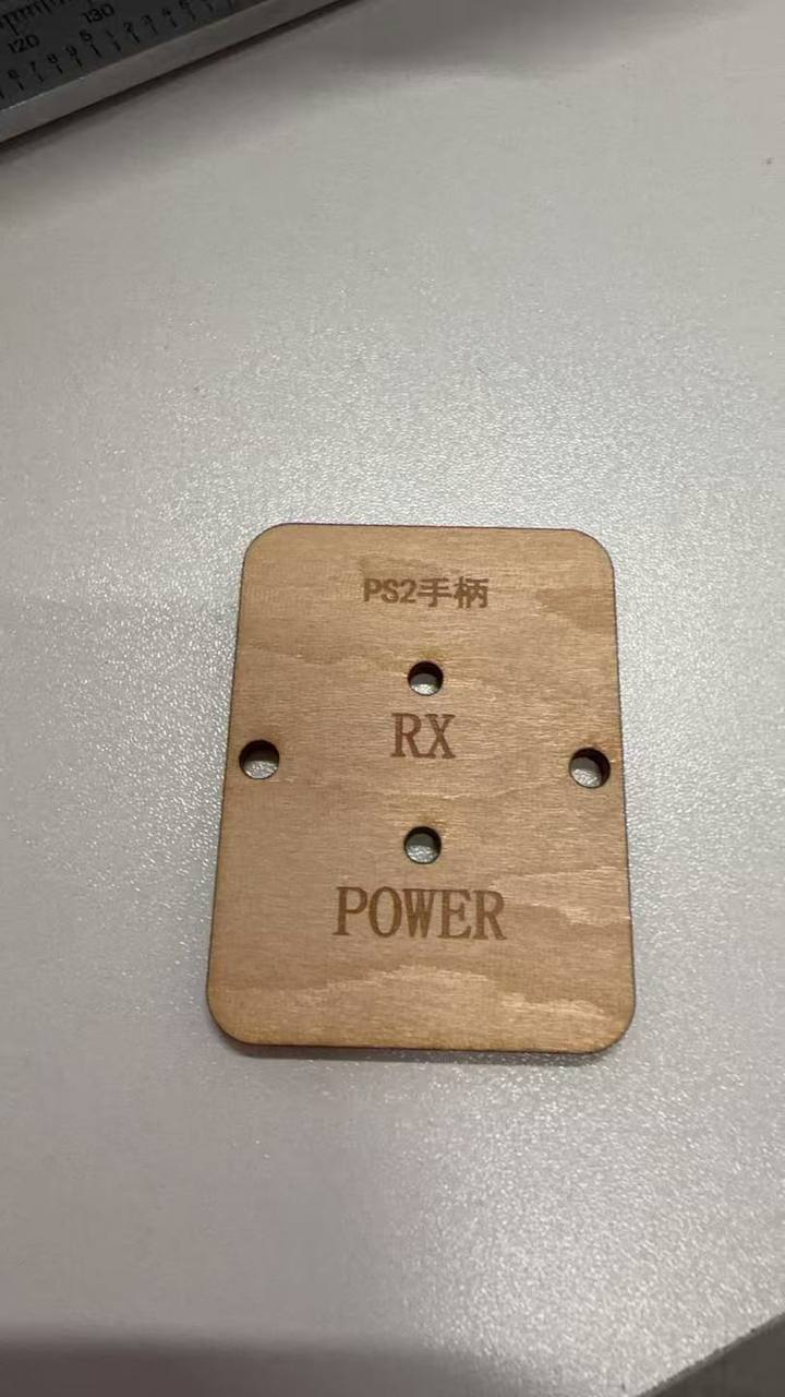
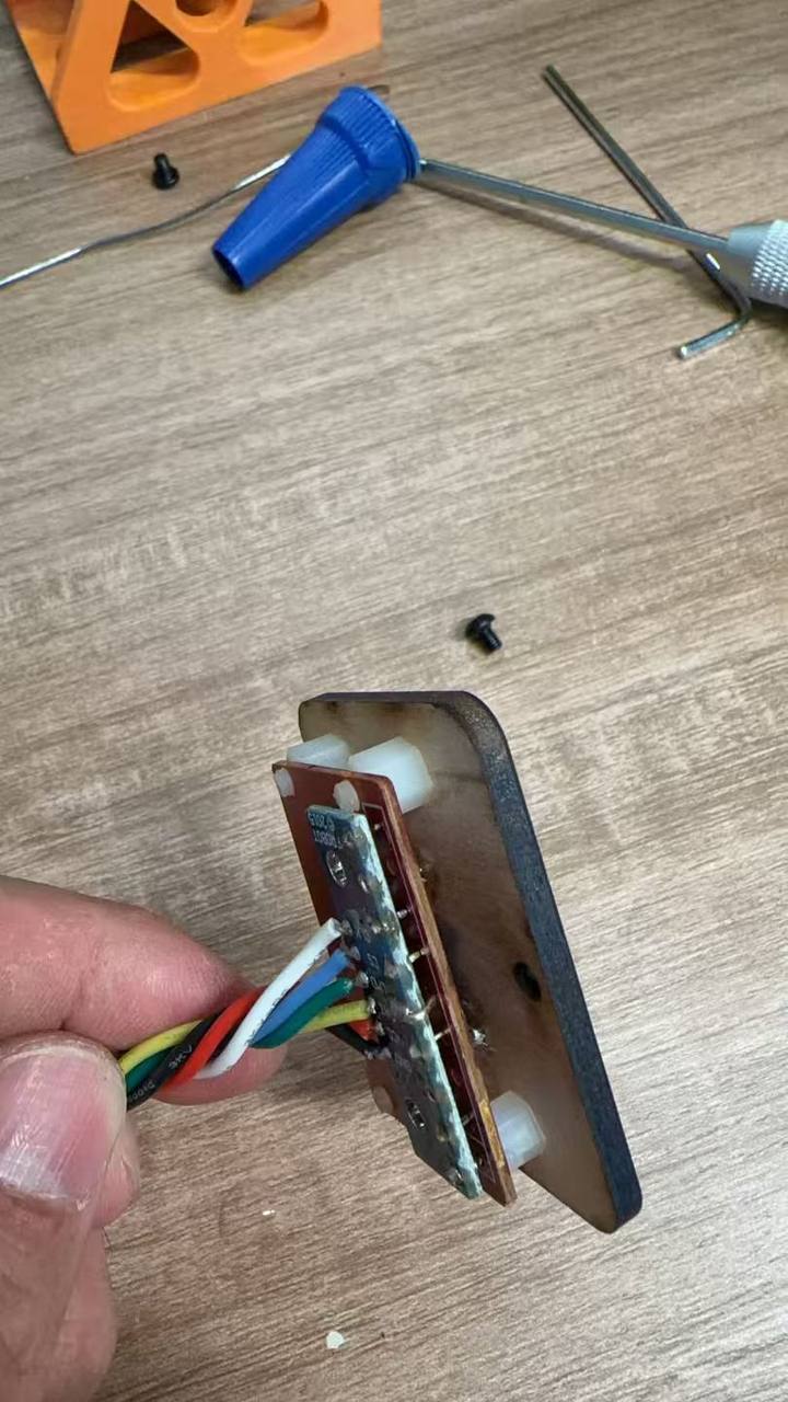
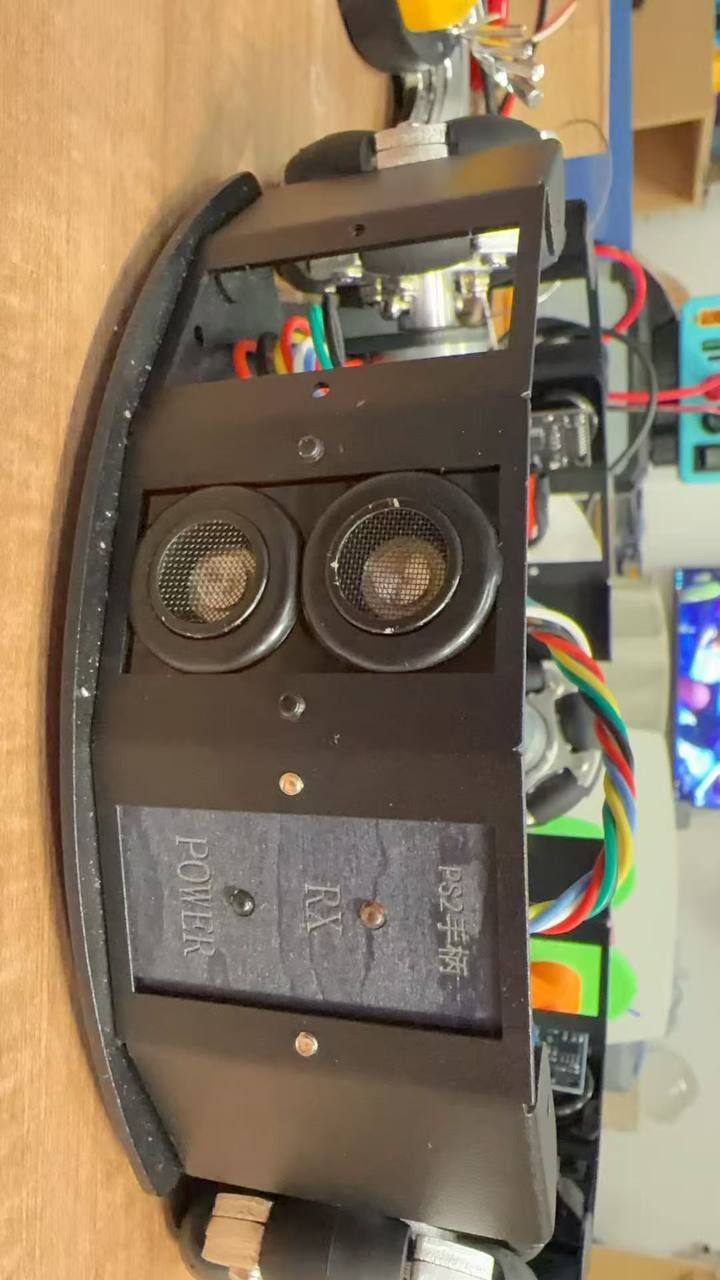
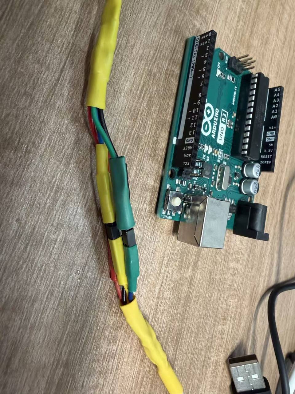
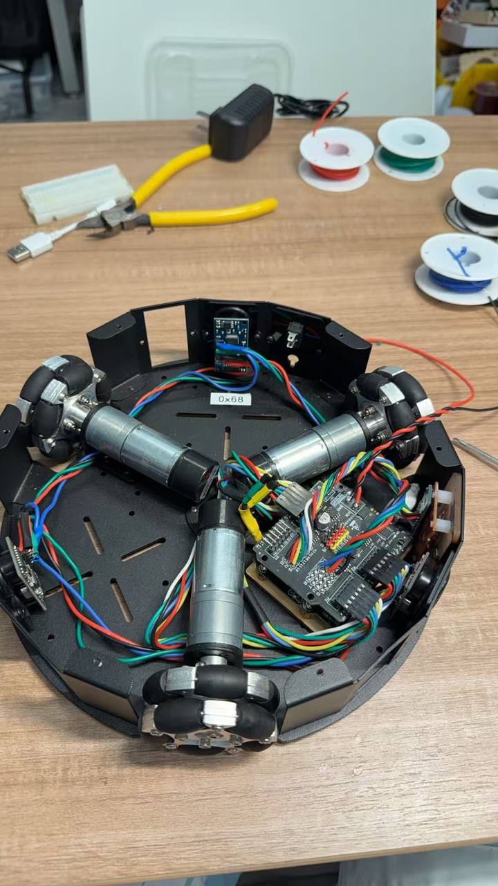
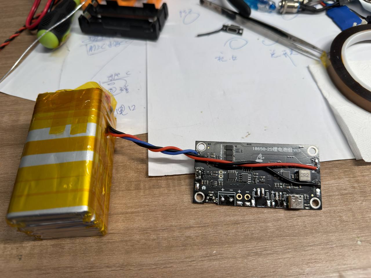
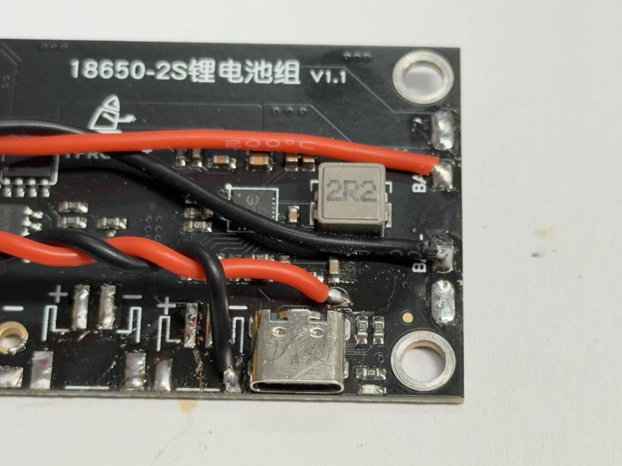
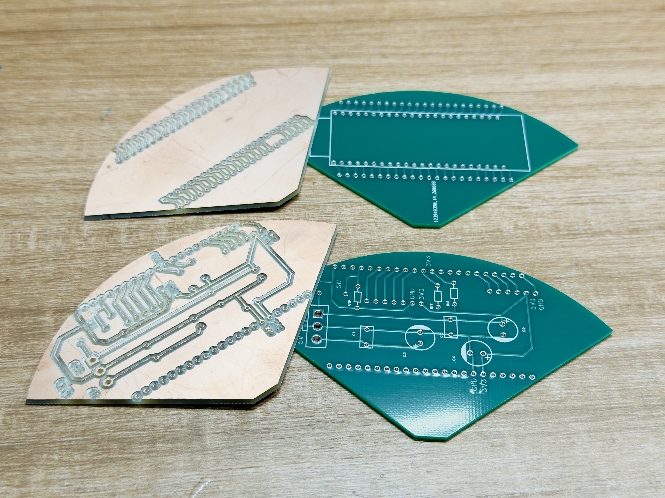
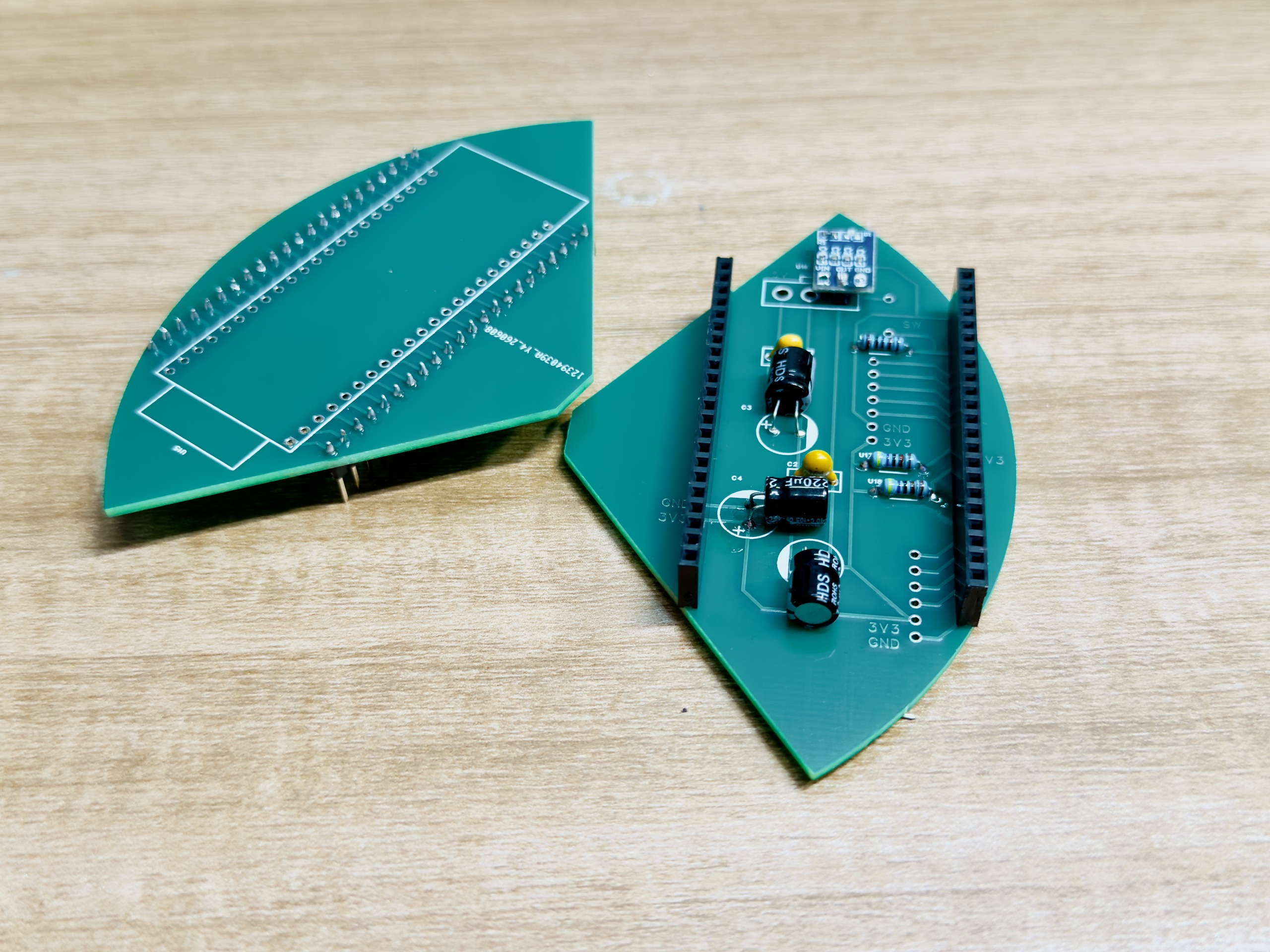
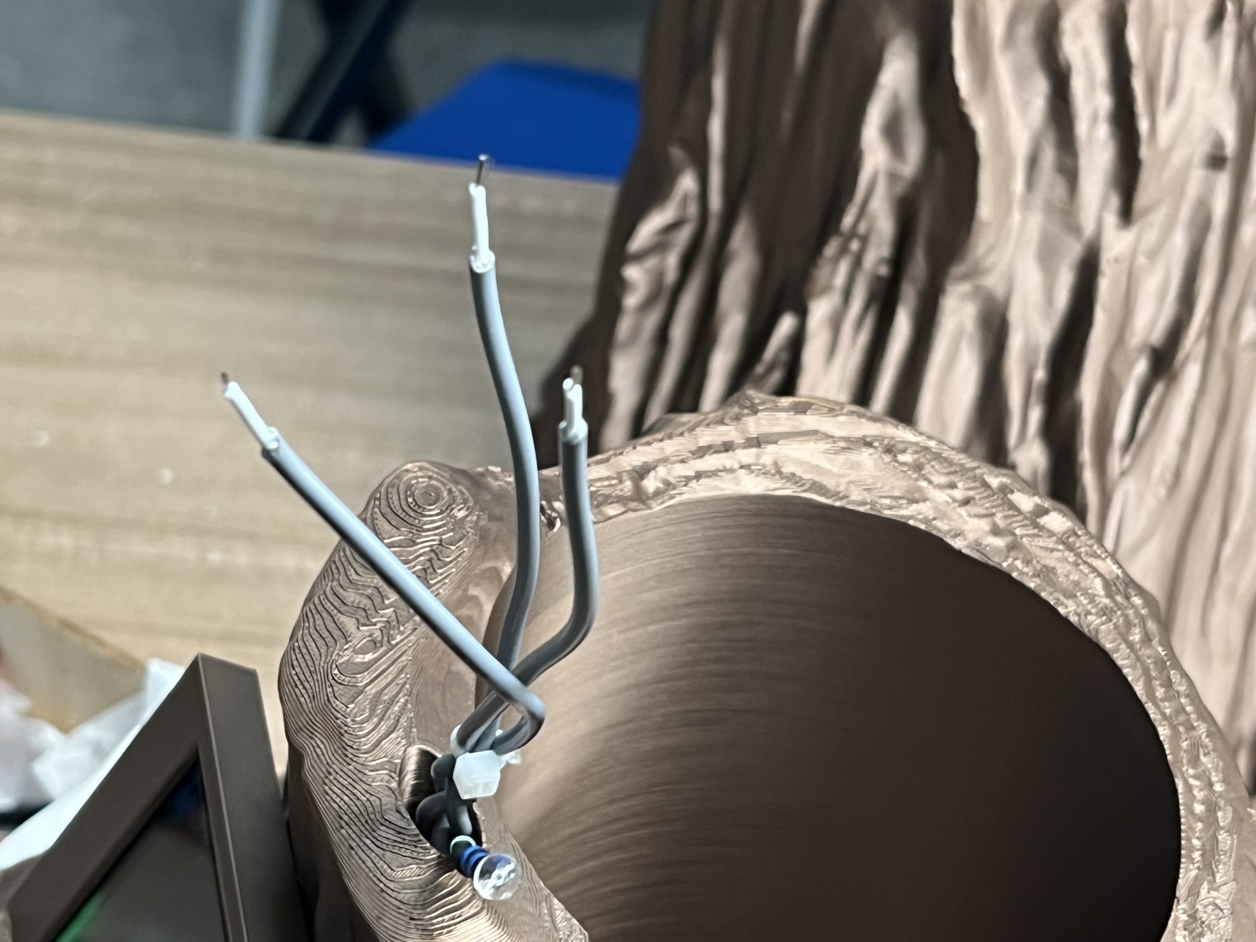
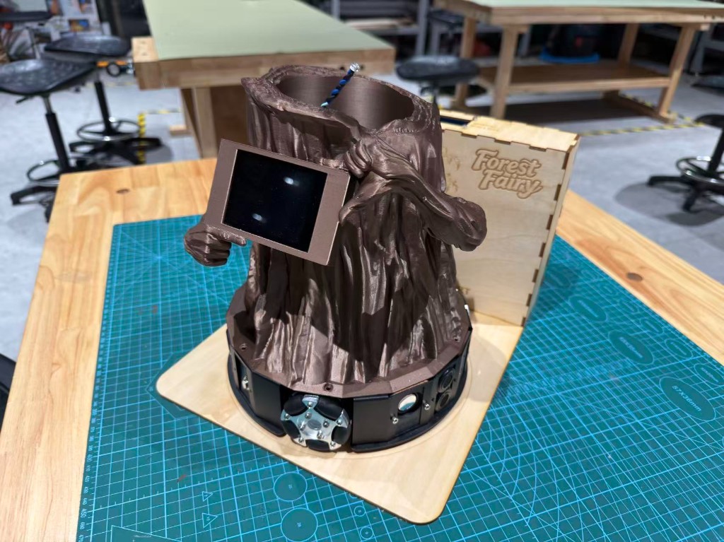
Forest Fairy charging dock — build chronology (photos)
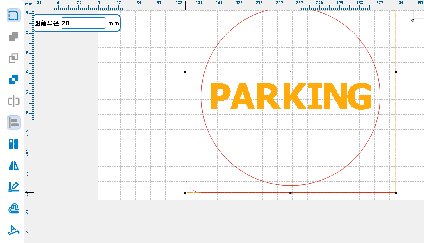
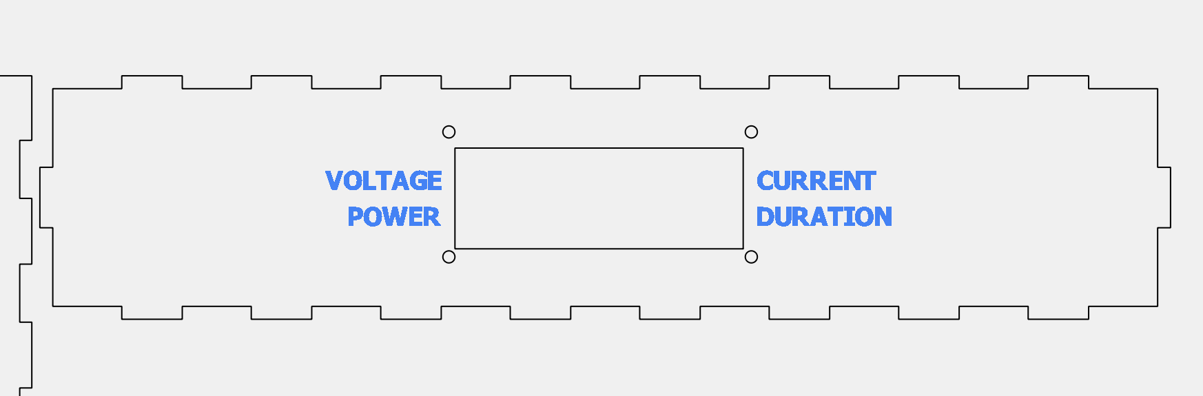
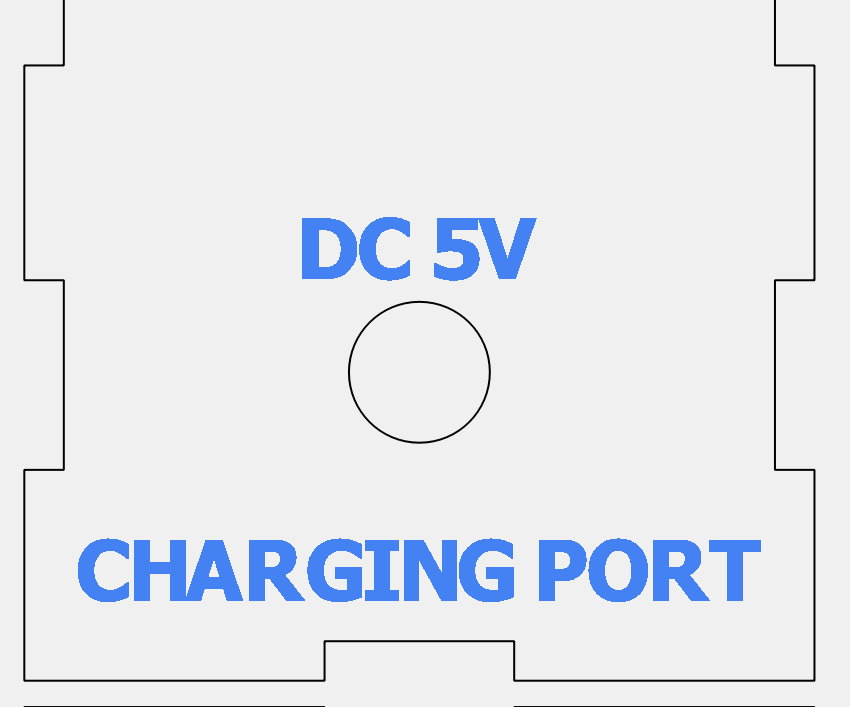
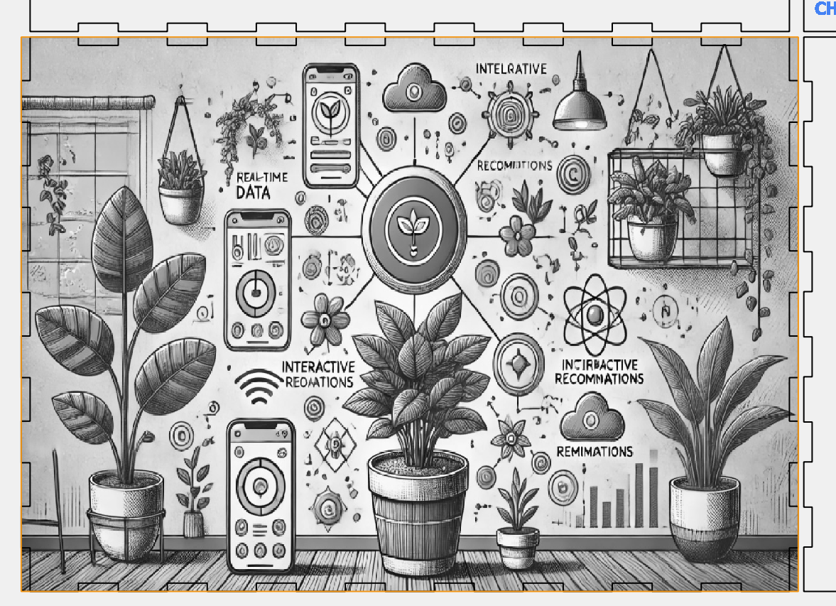
The companion charging dock (森之精灵充电桩) is a laser-cut wooden enclosure with magnetic pogo contacts, a DC input, status LEDs, a wake button, a microphone aperture, and an LCD1602 window on the top panel. Below is the build log numbered 1–24 to match my working files; captions summarise each CAD, fabrication, and assembly step in English.

Materials (photo cross-reference)
The photo below is the Week 12 kit spread. The bullet list maps visible regions to roles; full assembly order stays in Build process.
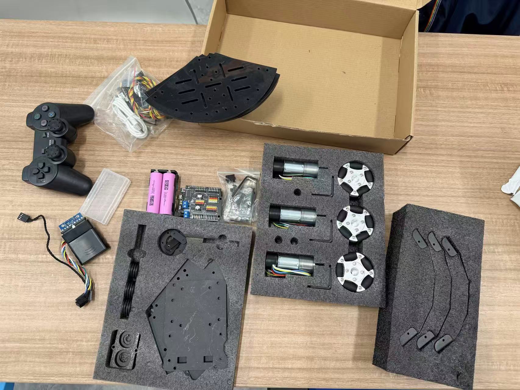
- Black plates and brackets: tri-segment circular deck and rim brackets—the holonomic skeleton.
- Three geared motors with encoder harnesses: each drives one omni wheel; encoders support closed loop, odometry, and speed estimates.
- Three omni wheels: with 120° geometry for omnidirectional translation and spin.
- Green main controller board: motor drive, power entry, and expansion headers in one.
- PS2 handset and receiver: human control and a path toward auto / manual mode splits.
- 18650 holder and cells: nominal ~7.4 V rail (confirm against the kit sheet and bench measurement).
- Fasteners and brass standoffs: stacking, grounding strategy, and mechanical isolation.
Upper structure (planter side): metal / acrylic backbone, custom PCB bay, printed pot, and cable bosses—see Week 2 CAD, Week 5 FDM, Week 6 schematic/PCB, and Week 8 fabrication & assembly.
Tools, computers, and skills
- Fabrication and measurement: 3D printer, hand tools, multimeter, oscilloscope (for analog front ends and buses), soldering and rework, optional CNC when a mechanical part demands it.
- Digital workflow: Blender / CAD, KiCad, fab-house exports and incoming inspection.
- Computers and skills: ESP-class firmware build and flash, serial and network debugging, basic circuit diagnosis; for bio signals, patient baseline and calibration work so noise is not misread as narrative.
Schedule (effort by Fab week)
These are elapsed effort slices tied to course weeks—not a commercial quote. Use each
weekNN.html as the lab notebook spine:
- Structure (planter + base interface): from Week 2; concentrated FDM in Week 5.
- Circuit design and boards: Week 6 through Week 8 (revisions and receipts).
- Holonomic assembly: Build process; mixing matrix, ultrasonics, and environment extensions continue alongside Week 11 and later final-project notes.
- Display/UI, sensing, integration: spans Week 4, Week 9, Week 10, Week 15, and beyond.
Rolling plan: final-project-weekly-plan.md.
Photo walkthrough (build order)
Each milestone is documented as photos plus narrative on the linked week. This section shows one frame per stage; the numbered story with deep links lives in Build process above.
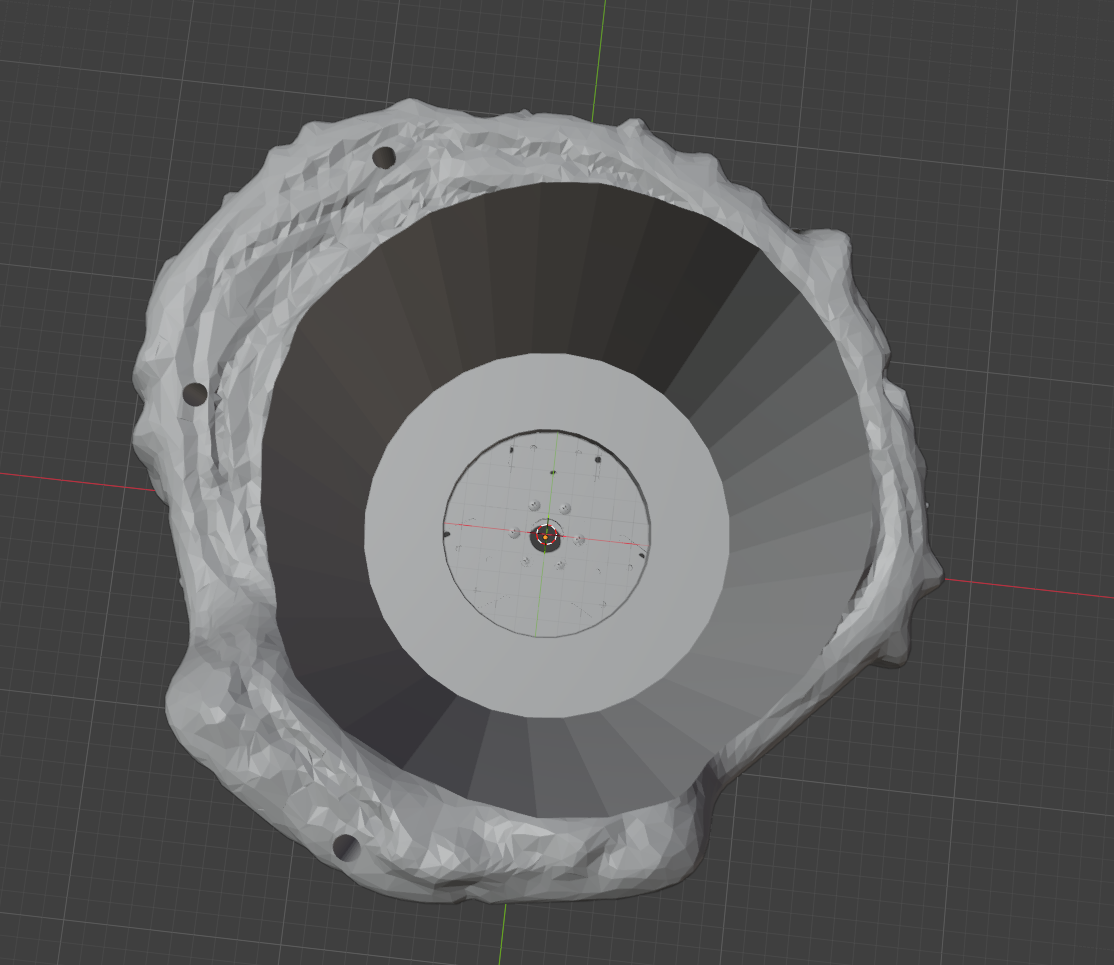
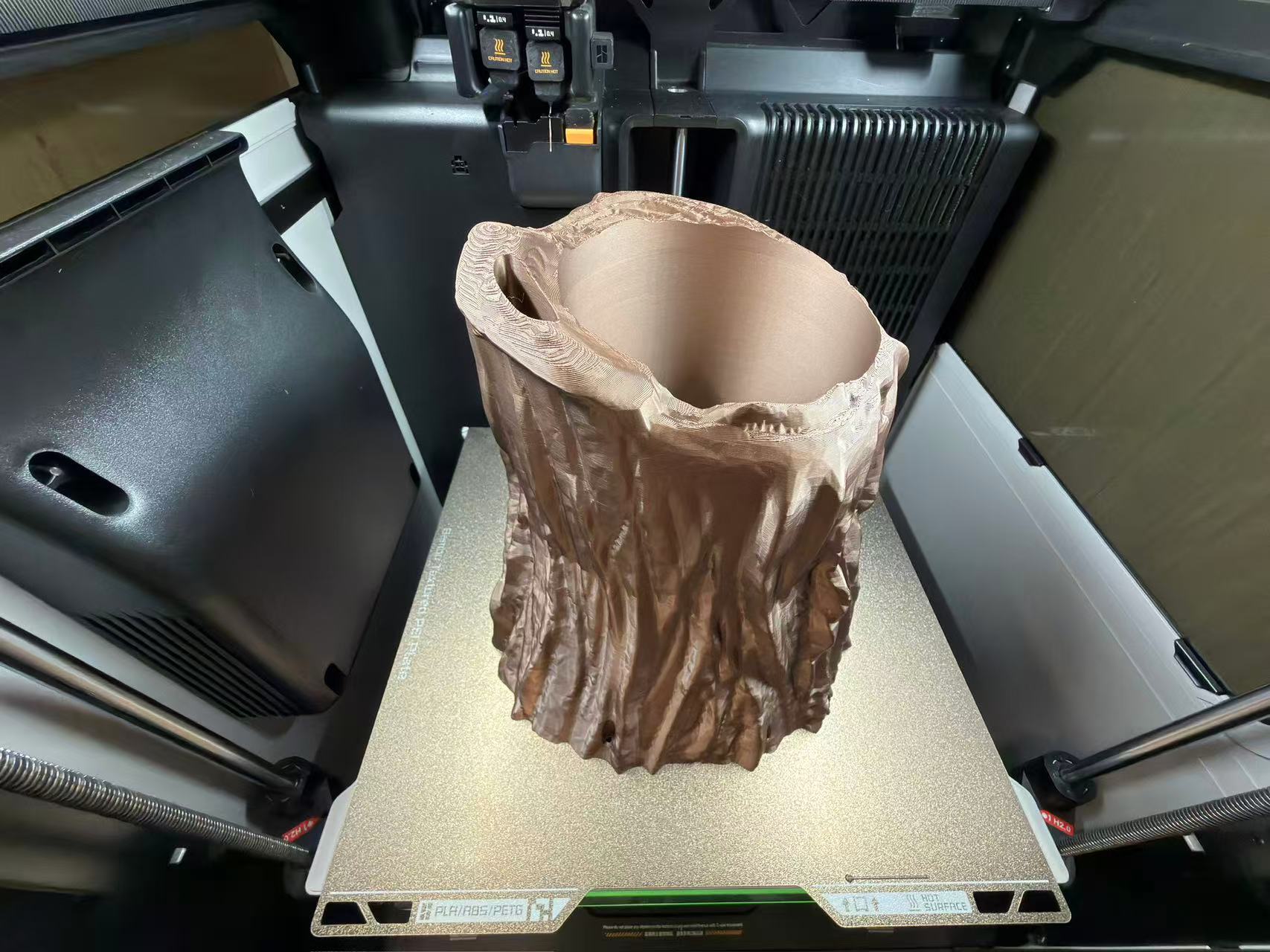
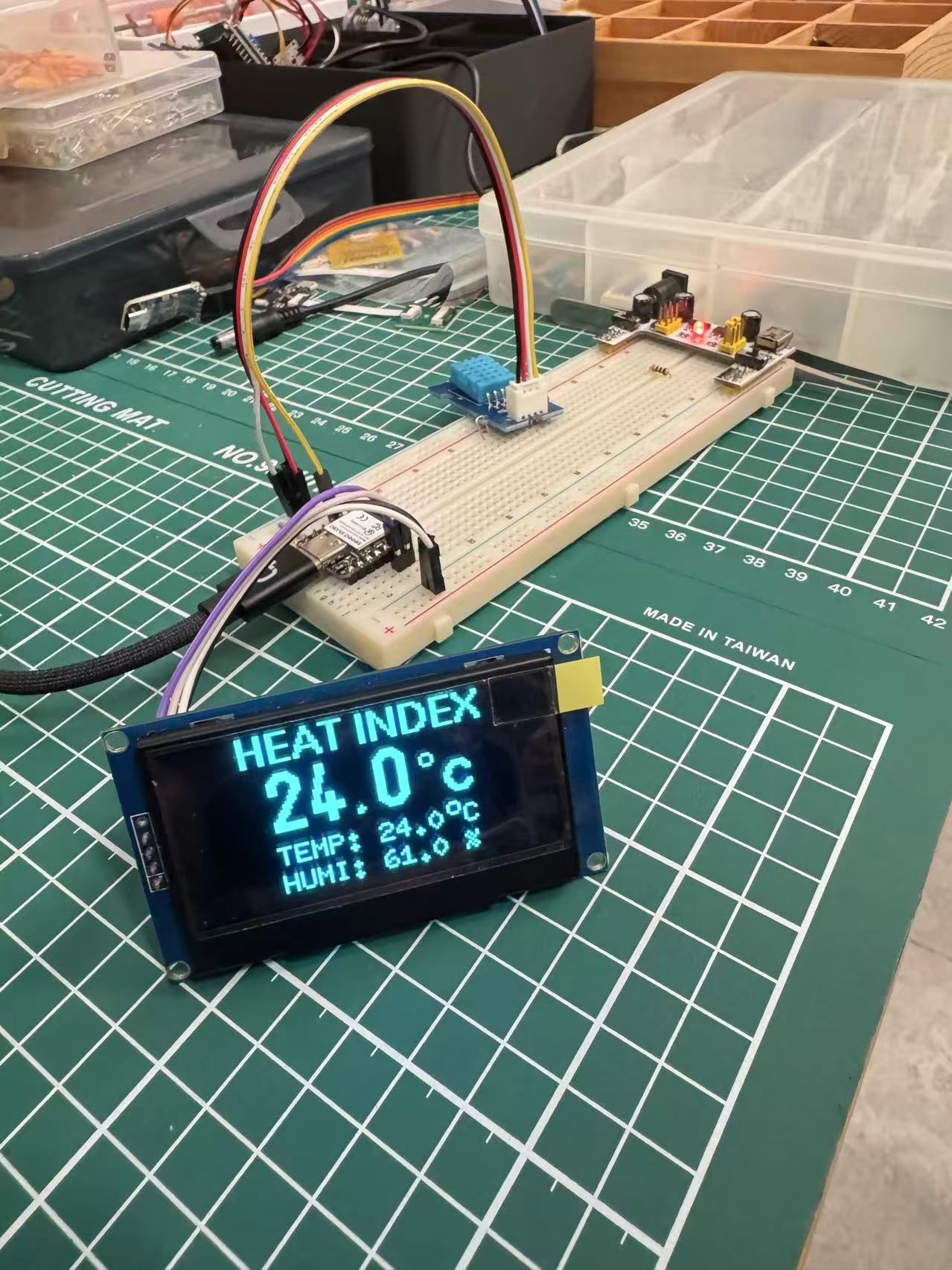
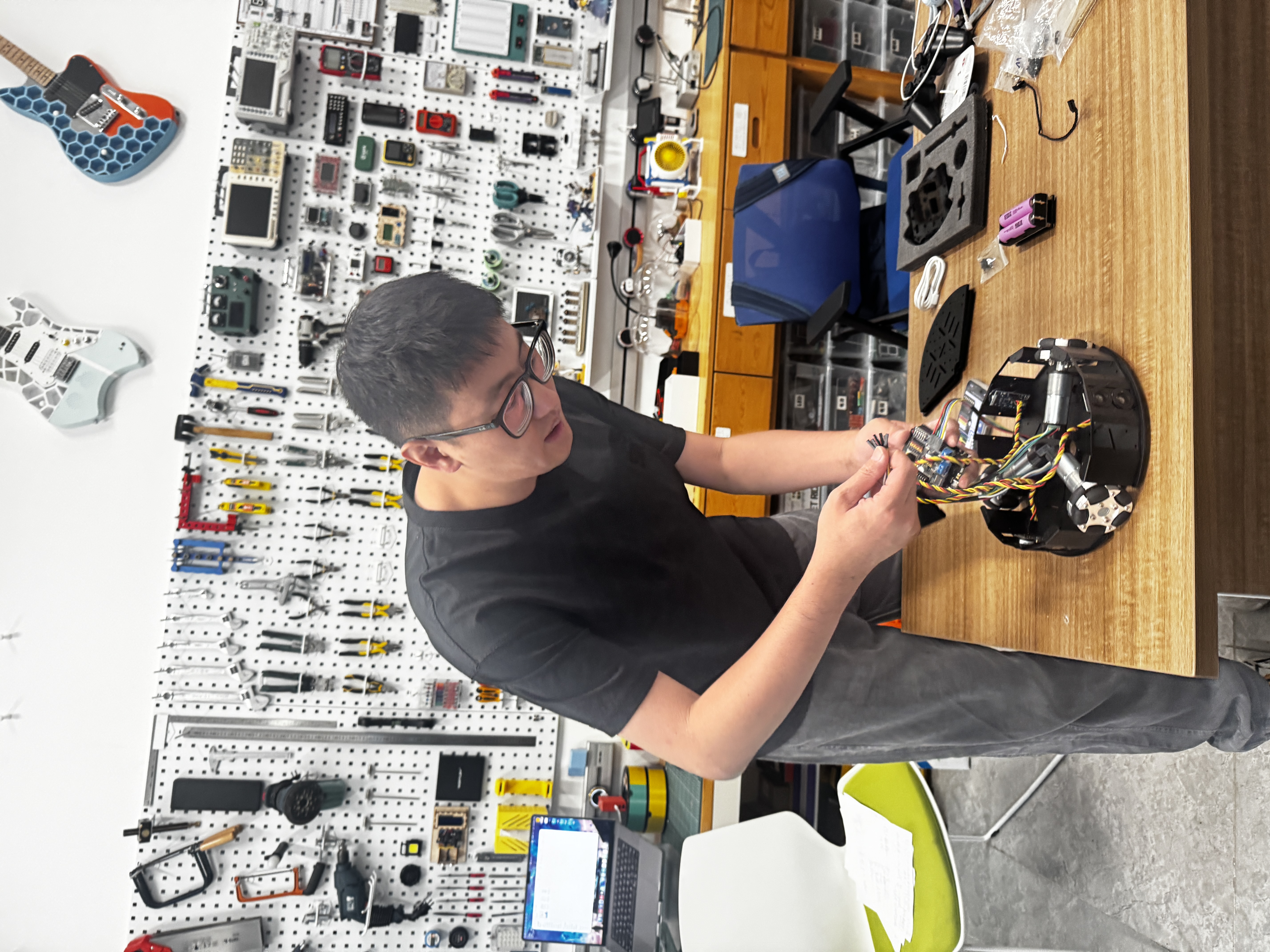
3. Software report
TFT user interface — design process and on-board results
Instructor feedback asked me to explain how I built the TFT application, how data reaches the screen, and to show results on the board I designed—not only a browser mockup. Below is the path I actually took, from paper sketch to firmware running on my ESP32-S3 WROOM + ST7789 + FT6336 stack on the carrier I routed in Week 6 and populated in Week 8.
From paper wireframe to HTML prototype
I started on paper: block layout, swipe direction, and four functional areas I knew I needed early— environment / plant info (temperature, humidity, light from the plant’s surroundings), soil parameters, a plant mood page (stress / nitrogen visual), and an AI dialogue panel. That sketch became the contract before any pixels hit silicon.
Next I used AI-assisted HTML to freeze the look at the real pixel budget: one file with five horizontal panels in a swipe container, each sized to 320×240 landscape—the same window the ST7789 uses after rotation. I iterated in the browser until spacing, titles, and metric rows felt readable at arm’s length. The full mockup trail lives on Week 15 §5, including the paper sketch and exported panel captures.
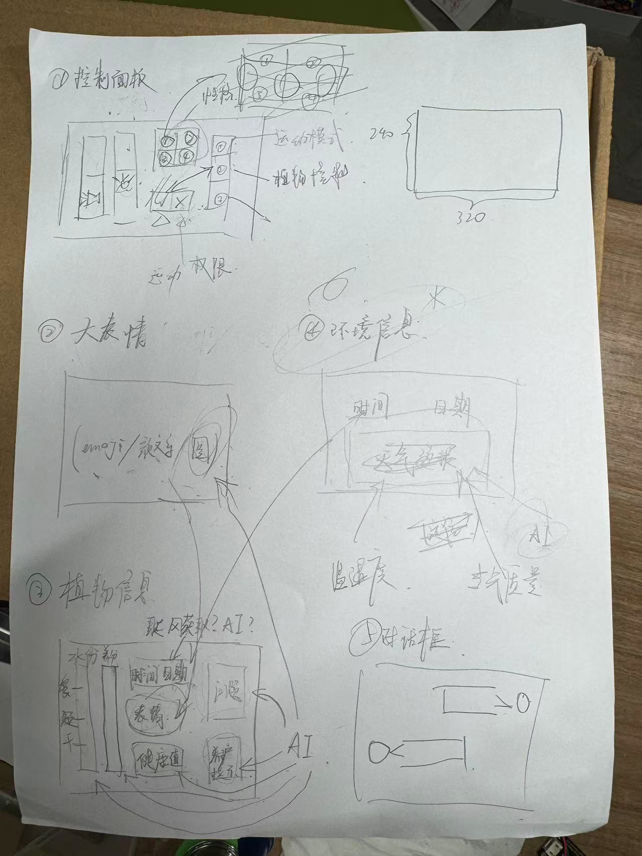
HTML reference (same layout as firmware): open mockup · download HTML
Porting the UI to the TFT (SPI display + I²C touch)
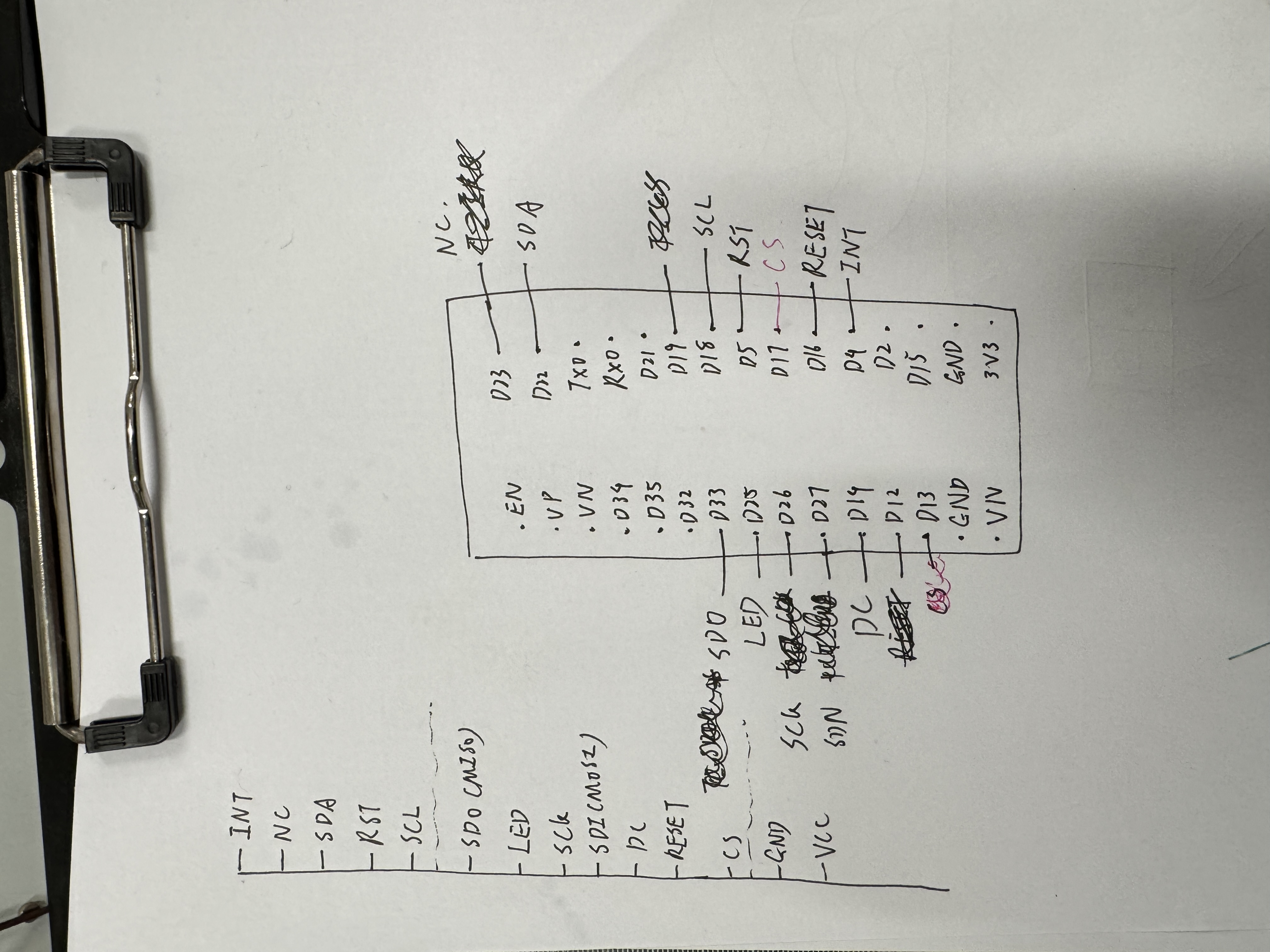
I connected the ESP32-S3 WROOM module to my ST7789 panel over
SPI (CS/DC/RST/backlight on the pins in
board_pins.h) and the
FT6336 touch controller over I²C (address 0x38, SDA/SCL on
GPIO6/GPIO15). Horizontal swipes on the touch layer advance five pages in the same order as the HTML prototype:
Emoji → Plant → Environment → Control → Chat.
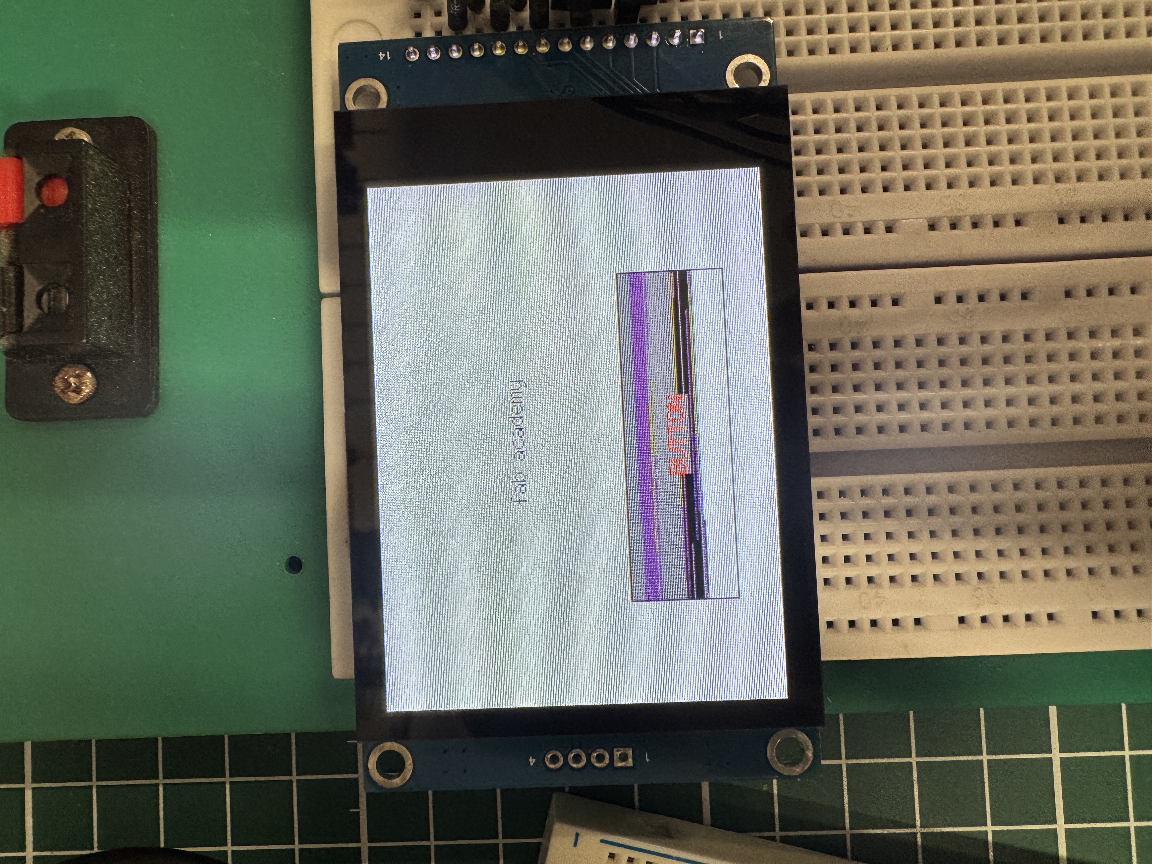
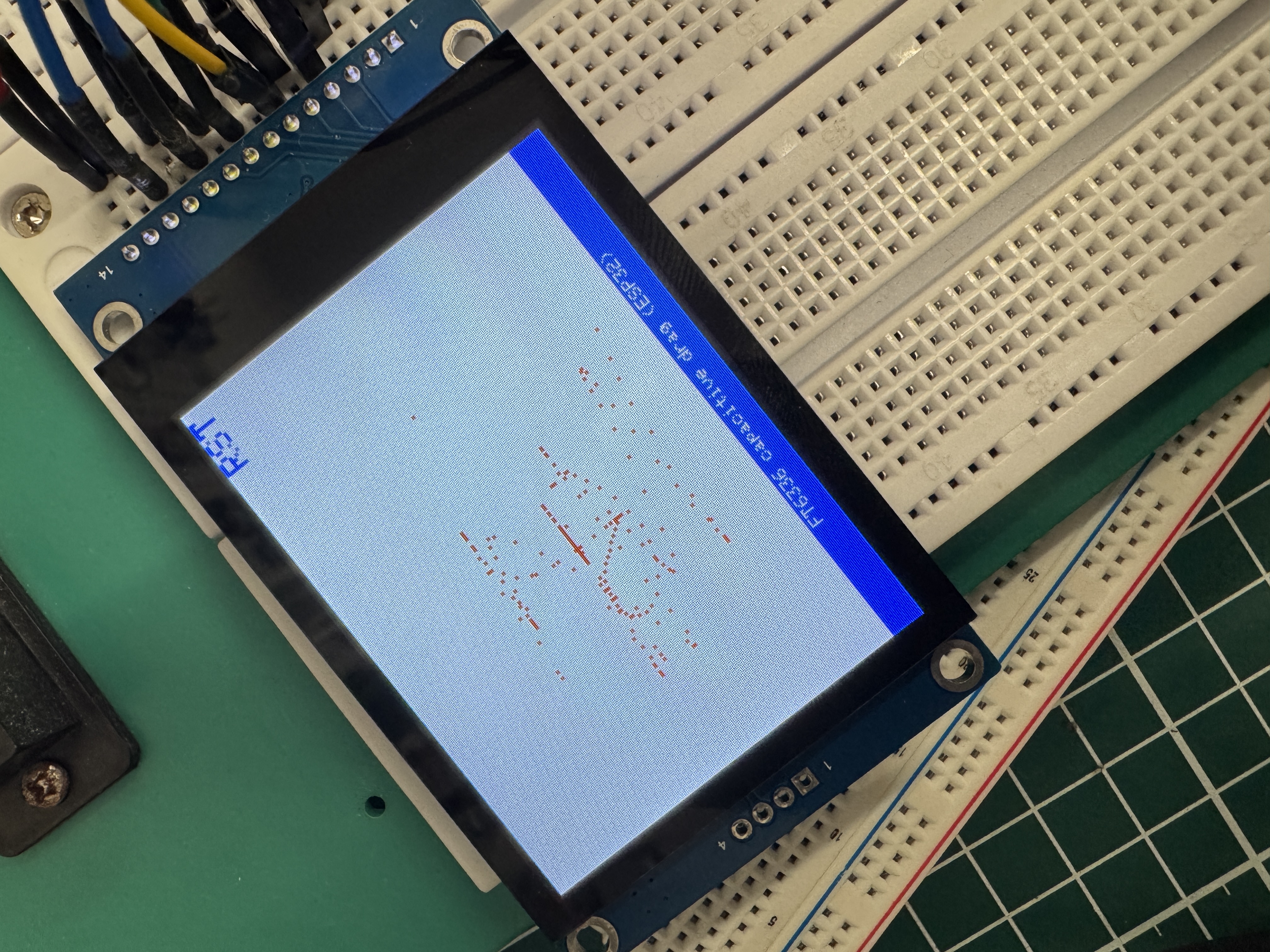
How the interface is created in firmware
The shipping UI lives in
wroom-upload/src/main.cpp
with page-specific drawing split into helpers such as
chat_draw_wroom.cpp
and
cell_net_ui.cpp.
Each page is a function that paints header, metric rows, and footer dots into a fixed 320×240 framebuffer using
Adafruit_GFX primitives (fillRect, drawFastHLine, U8g2-backed text).
Swipe detection compares touch down/up positions with a horizontal-dominance threshold; on page change the
firmware clears only the content band and redraws that page’s widgets—matching the HTML panel boundaries I
defined in the mockup.
Data handling, updates, and communication to the display
-
Display path (SPI):
Adafruit_ST7789pushes RGB565 pixels over SPI at ~26 MHz (TFT_SPI_HZinboard_pins.h). Backlight is PWM on GPIO17. -
Touch path (I²C):
ft6336_touch.hpolls the controller, applies calibration / axis inversion, and feeds swipe events to the page state machine inloop(). -
Plant / environment data (optional I²C HostLink): when the XIAO sensor hub is connected,
env_i2c_slave.cpplistens at slave address0x55for framed commands (i2c_env_link.h)—telemetry0x01, plant nitrogen status0x07, assistant text chunks, wall-clock lines, etc. Incoming frames bump a version counter; the UI redraws Plant / Mood rows on a throttled interval so I²C traffic does not flash the panel. -
Soil probe (UART Modbus):
soil_sensor.cppreads a TTL Modbus probe on UART2 and fills the Soil page metrics (moisture, temperature, pH, EC, N/P/K). -
AI chat: voice and cloud dialogue run on the same WROOM board (Wi-Fi + Bailian WSS); assistant
strings stream into the chat page via
local_chat.cpp/chat_draw_wroom.cppwhile TTS plays on I²S.
The block diagram below is the integration map I used while wiring buses; the TFT/UI node is the WROOM path described above.
Libraries, framework, and tools
- Framework: Arduino on ESP32-S3 (PlatformIO, env
esp32s3_senlin). - Display: Adafruit GFX, Adafruit ST7789, U8g2_for_Adafruit_GFX (mixed Latin / CJK labels where needed).
- Touch: custom FT6336 driver over
Wire(100 kHz). - Networking / voice: ESP32 Wi-Fi stack, custom WebSocket client + Bailian dialog client, I²S mic/speaker drivers.
- Design tools: paper sketch → AI-assisted HTML/CSS mockup → Cursor for firmware port and iteration.
- Flashing:
pio run -t upload/ serial monitor at 115200 baud; pin and protocol notes incode/final-project-upload/README.md.
Original source code (download)
Per assessment requirements, the original upload firmware from my 2026‑06‑22 delivery bundle
is archived in this repository. API keys and Wi-Fi passwords are not included—copy the
*.example headers locally before building (see README inside the tree).
- Download all FINAL upload firmware (ZIP) — WROOM UI, optional XIAO/PICO sensor paths, Uno chassis, charging dock.
-
Browse:
code/final-project-upload/· primary UI:wroom-upload/· optional sensor hub:s3-upload/ -
Earlier bench / integration tree (Week 15–16 debug):
code/week15-individual/final/
Build reminder:
cp wroom-upload/src/wifi_secrets.h.example wroom-upload/src/wifi_secrets.h and the matching
Bailian header before upload. Full flash order and serial acceptance checks are in
wroom-upload/README.md.
Environment and platform
- Edge MCU: ESP32-class devices handle configuration, sweep/acquisition scheduling, links, and safety interlocks; carrier iterations are summarized under Week 6 revision 2, with bring-up context in Week 8.
- Sensing stack: LMP91000-class potentiostat / analog front end, AD5933 impedance path (excitation, sense, DFT), orchestrated by ESP32 register traffic—schematics in Week 6.
- Human interface: local display and alerts in Week 10; embedded simulation in Week 4; higher-level IDE comparisons in Week 15; networking foundations in Week 11.
- AI and orchestration: on-device or split edge/cloud feature work and dialogue policy; copy must stay tethered to plant state and uncertainty (notes to grow across Week 16– Week 20).
Functional blocks
- Acquisition service: light, temperature, humidity, soil and nutrient-related channels, plant-side electrochemical/impedance time series, timestamps, and contextual metadata.
- Interpretation layer: clusters changes into families—acute threat (prolonged drought, mechanical insult), environmental migration (light/temperature/humidity shifts), and subtle endogenous physiology when ambient conditions are stable—reducing raw curves to actionable prompts.
- Dialogue service: scenario-scoped utterances constrained by live signals and calibration state; explicit “unknowns” and unit discipline.
- Motion service: intent parsing, safety gating, and body velocity commands into the holonomic mixing matrix; obstacle and limit policy still in flight.
- Connectivity and home coordination: telemetry uplink, remote commands, gentle coordination with lamps, blinds, and similar loads—privacy and permissioning treated as a first-class design problem.
Software logic overview
The integrated firmware splits across the chassis carrier (ESP32-S3 hub), environment/display node, cloud voice path, and the dock-side status board. Local audio is captured on the device, sent to cloud ASR / LLM / TTS, then returned as screen text and speaker output. The diagram below is the working map I used while wiring I²C buses, serial bridges, and the sense → interpret → act loop.
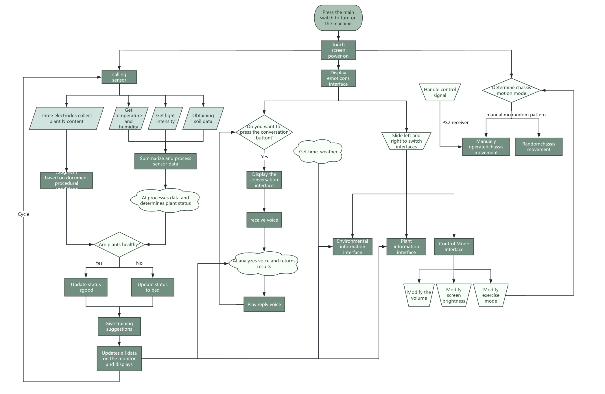
code/week15-individual/final/).
End-to-end integration
The architecture is a sense → interpret → act bus: acquisition publishes features on a steady cadence; interpretation emits a shared situation object for UI, speech, and motion; consumers subscribe and degrade gracefully (for example, stop drive, read-only display). USB serial and wireless links support development flashing and logging; secure boot / OTA belong to a later production pass. Concrete integration notes: Week 10 (readings → display), Build process (handset → wheels), Week 11 (network primitives), and Week 16 (system integration, packaging, and finished-product evidence).
Live display and environment-stack experiments: Week 10 — individual (OLED, sensors, libraries).
System integration documentation: Week 16 — packaging, final-product evidence, and integrated wiring.
4. Debug & test report
Electrical bring-up, flashing, and bench compatibility
Before trusting any plant-side story, the stack has to survive ordinary embedded risks: battery and USB etiquette, motor phase conventions, I²C/SPI address clashes, and ESP32 task timing when sampling competes with UI work. Flashing follows the Arduino / ESP toolchains in the weekly logs; I use low-duty PWM smoke tests before full torque so a wiring mistake does not become a mechanical one. Photos and sequences are in Week 8, Week 10, and Build process.
Nanostat on the leaf: mounting measurement where the plant lives
The Nanostat front end is not only validated on a fixture; I mounted it on real leaves so contact geometry, pressure, and stray coupling resemble field use. The intent is electrochemical / bio-interface data from living tissue—not a pristine glassy demo—while logging enough metadata (leaf ID, side, time since watering, DHT context) to read the trace responsibly.
Theoretical baselines, live captures, and Mimiclaw
Each capture is compared to a theoretical or reference expectation: textbook shapes, intuition from spice-like reasoning, datasheet envelopes, or quiet baselines from prior sessions on the same plant. Instead of hand-aligning every overlay, both expected and measured curves feed Mimiclaw as one workspace—residuals, gain errors, drift, and event tags (e.g. post-water, post-light change) stay in a single view instead of scattering across files.
What “debug” means once Mimiclaw is in the loop
Debugging is less about nudging one print statement and more about inspecting and correcting Mimiclaw’s comparison results. When theory and measurement diverge, I question leaf contact, wet reference electrodes, whether excitation matches the model, or whether the plant crossed a physiological edge the simplified theory never encoded. Loop: capture → Mimiclaw → read the comparison → adjust analog settings, mechanical coupling, or the template → capture again. Sensor weeks remain the notebook spine ( Week 6 — Nanostat routing, Week 9, Week 10); Mimiclaw is where the overlays converge.
Methods, logging, and lab support
Baselines stay honest: labeled interventions (water, shade, pot moves), cross-checks against commercial environment sensors, and complete notes on excitation and electrode geometry. Raw plots land on weekly pages as measured; this document stays methodological rather than inventing numbers. Isolation testing (sensor, then actuator, then closed loop), paired controls on one plant, and informal reviews with instructors and peers still catch what automated diff views miss.
5. Application & upgrades
Where the hardware is today
The holonomic base and printed structural pieces are far enough along to demonstrate in person. The full plant-side analytics loop and polished conversational AI are still converging; weekly pages remain the honest timeline as those gaps close.
Upgrades since the first sketch
- The design text now states plainly why human vital-sign metaphors must not be pasted onto plants and why biological noise must not be sold as drama—constraints that flow back into Mimiclaw and any conversational stack.
- Committing to three-wheel holonomic geometry forced early kinematics and sign conventions, shrinking firmware guesswork on the mixing matrix ( Build process).
- Co-developing PCB outlines, carriers, and the planter shell exposed wiring and tolerance problems earlier than serial weekend hacks ( Week 6, Week 8, Week 2).
- Passive irrigation inside the printed shell: hollow a water reservoir into the 3D-printed wrapper around the pot, line the wall with a wicking or capillary material (felt, geotextile, or another rated porous layer) so moisture reaches the substrate gradually instead of dumping instantly. Refill on a human cadence—or later a small pump—and the cavity buffers dry spells while Nanostat data checks whether the plant agrees with the hydraulics. Print seams, sealing, algae control, and overflow need the same engineering hygiene as any self-watering planter; the design goal is to merge care mechanics with the character form instead of bolting a saucer underneath.
Open engineering debt
- Species and potting-mix generalization needs far more labeled data than one term allows; Mimiclaw helps compare runs but cannot manufacture ground truth.
- Long-term lithium strategy, e-stop behavior, ledges, and carpet friction belong in a safety review, not only a reel.
- If a cloud model joins later, consent, retention, and offline behavior must be designed—not assumed.
6. Manual & specifications
How to operate the prototype
- Set up: secure the plant in the pot and protect root-zone electrodes if installed; place the base on flat ground with nothing trapped in the wheels.
- Power: wire the pack with correct polarity; before first energize, read torque and cable routing guidance in Build process.
- Development control: use the PS2 handset to verify wheel directions and mixing-matrix signs; keep serial logging open for firmware traces.
- Networked control (when enabled): follow the device notes for provisioning; remote motion commands should include rate limits and an emergency stop path.
- Maintenance: recalibrate temperature, humidity, and light paths periodically; clean or reseat electrodes using the same disciplined baselines described in the debug section.
Replication checklists: Build process and linked weeks.
Who it is for, where it runs, what it does
- Audience: growers, students, and researchers willing to maintain small electromechanical systems.
- Environment: indoor flat floors with controlled lighting for demos—not an all-weather outdoor robot.
- Function: translate plant condition into actionable cues, limited autonomous motion, and optional dialogue—continuous care rather than a one-off “smart vase” gimmick.
Draft specifications
Targets only—confirm against final BOM, measurements, and weekly updates. Safety-critical electrical numbers must be revalidated on the shipped physical configuration.
| Category | Item | Notes / target |
|---|---|---|
| Mechanism | Locomotion | Three omni wheels, 120° holonomic layout |
| Mechanism | Upper structure | 3D-printed planter + metal/acrylic frame (integration ongoing) |
| Power | Battery | ~7.4 V nominal 18650×2 pack (kit); verify cutoff/charge strategy |
| Sensing | Environment | Light, temperature, humidity; soil moisture / nutrient-related channels |
| Sensing | Plant interface | 3-electrode potentiostat path + AD5933 impedance front end |
| Compute | Edge | ESP32-class MCU + optional ESP8266/BLE link |
| Interaction | Local / remote | Display, audio TBD; PS2 handset; future phone client |
| Biology | Subject plant | Capsicum spp. — chili pepper (辣椒; live demo subject) |