Week 2: Computer-aided design
Week 2 individual work splits into two CAD tracks. First, a 2D laser workflow for an Elsa / ISA Innovation Centre tech–music violin wall bracket: vector booleans in LaserMaker, a real cut on the lab machine, and spray finish with laser-cut masks. Second, 3D CAD in Blender for the final-project planter on the omni-wheel base. FDM print verification comes later on Week 5; this page keeps the bracket story and Blender mesh pipeline together. I also note how I shrink screenshots and clips for site uploads (same pass in the group section).
Individual assignment
What I was trying to cover this week
I kept two tracks. On the laser side I wanted the full loop on one page: CAD booleans, motifs from a small music-symbol library file, machine time, then masking for two-tone spray. On the 3D side I documented Blender CAD for the final-project planter on the omni base (eight-step mesh workflow from import through mask booleans). I rewrote the laser section to match what I actually did; the filenames on my captures already spell out the design order. Week 5 later tested that Blender mesh on the printer.
Laser-cut flat design: Elsa tech–music violin wall bracket
I wanted one panel that felt like Elsa / “ISA Innovation Centre” sci‑tech but still worked as a music object: circuit-like engraving, a clear layout for the hook / magnets, and motifs I could reuse instead of redrawing. I worked in LaserMaker, using its vector tools and booleans the way my screenshot filenames tag each stage (“design 1…4”). On the machine I ran mark/cut on approved sheet stock, then finished with clearcoat and two-tone spray through laser-cut masks so paint never flooded the fine engraved lines.
2D software: LaserMaker (what it is, install, rough workflow)
LaserMaker is the lab’s paired 2D vector + laser CAM package: I draw and boolean-cut ornament on one canvas, assign cut vs engrave by color or layer as the machine expects, then send the job to the cutter without round-tripping through a separate illustration app. That keeps kerf, fill, and small engraved strokes in one place, which matters for a panel where art and mechanical holes share the same outline.
Getting the app: I installed it from the vendor’s software portal (pick the build that matches the lab PC or my laptop (typically Windows x64; macOS builds are listed when available). Official download and updates: LaserMaker official software portal — downloads & docs. Flow on a new machine: open the site → download the installer for my OS → run it → sign in or activate per lab policy → confirm the laser model/driver preset matches our bench before drawing.
Rough workflow in LaserMaker for this bracket: new document → set
artboard / stock size → sketch functional regions (hook, holes) →
boolean union for one outer contour → add engraving graphics (circuit texture, badges) →
duplicate geometry into mask plates for spray → assign process colors → simulate / send.
The motif library is a separate .lcpx so I can import or copy consistent
music symbols instead of redrawing staffs each time. See Design 1–4 below and the downloadable projects
at the end of this section.
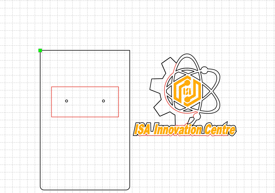
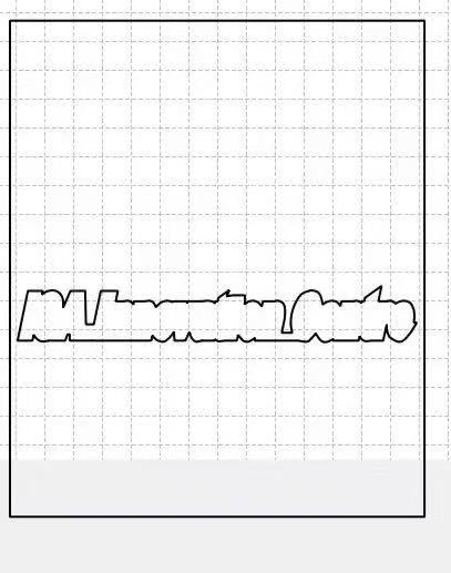
Design 1: sheet size, hook zone, and decoration plan
First I locked the board outline, the functional regions (hook pocket, fastener holes), and the mix of STEM + anime-adjacent ornament I could actually cut cleanly. Getting this right early saved me from splitting hairs on booleans while the vectors were still messy.
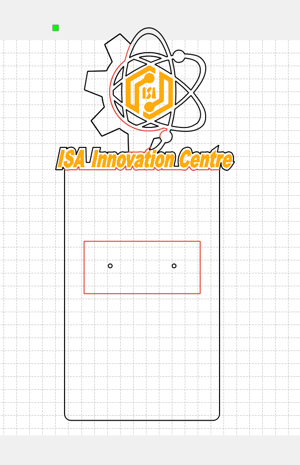
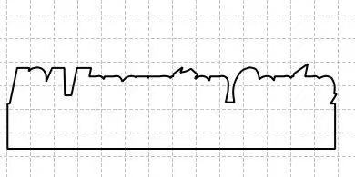
Design 2: unions for one clean outer silhouette
I merged the ornamental outlines with the functional frame using boolean union so the outer profile was a single closed path the laser could follow without duplicate or orphan segments, which made it easier to color by process (cut vs engrave) in the CAM side of LaserMaker.
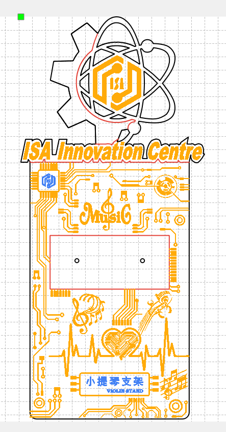
Design 3: “circuit + 二次元” graphic pass
On top of the silhouette I layered the circuit-board texture, badge shapes, and the flatter graphic strokes that carry the “tech” theme. I watched minimum feature size so skinny traces would engrave rather than vanish in soot, and kept pockets wide enough to sand later without erasing artwork.
Music-symbol motif library (separate .lcpx)
Staff lines and note heads repeat across the piece, so I did not want to freehand them each time. I keep a
small music-symbol library as its own LaserMaker project
(music-symbol-motif-library.lcpx), essentially my clip-art shelf. In the main bracket file I
import / copy-merge motifs from that library when I need another flourish, which keeps spacing
and note shapes consistent. You can download both the library and the assembled layout below in
Design files.
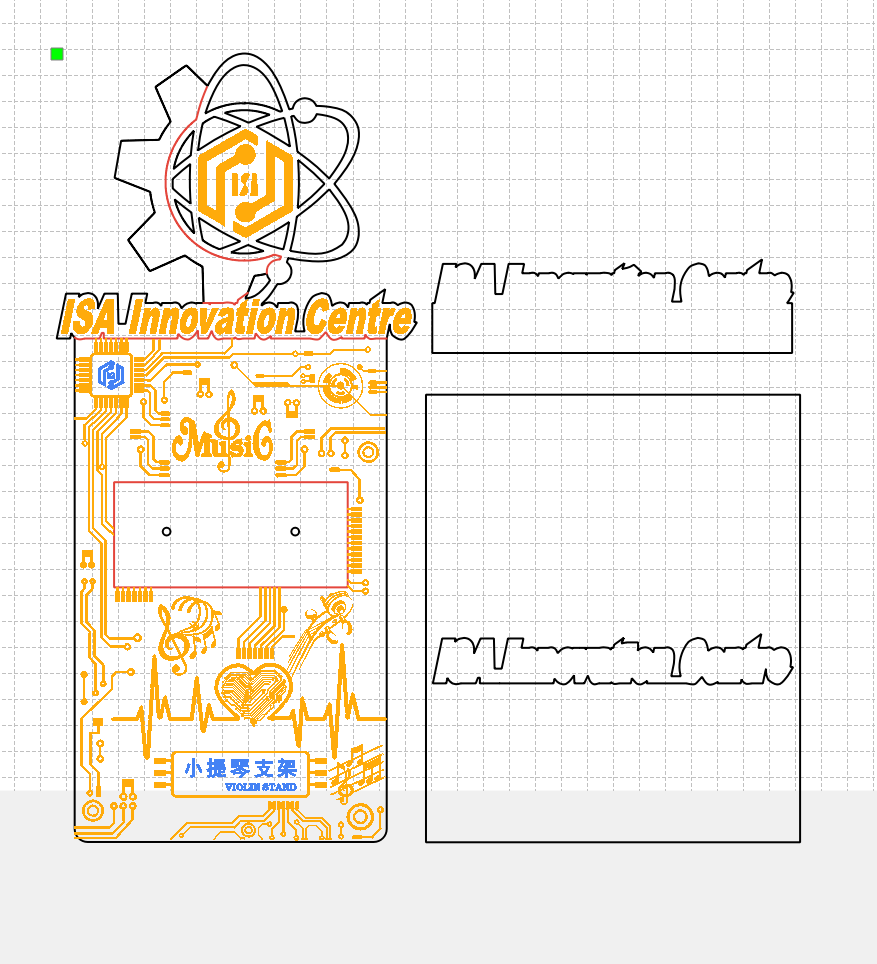
Design 4: laser-cut paint masks alongside the bracket
Spray paint is fast but sloppy without a plan. I drafted companion mask plates in the same CAD session: closed vectors that register against the real board and cover everything that should stay bare wood during a given color pass. The masks were cut from thin scrap on the same machine; the orange/black sequence below follows mask 1 → mask 2 so the two accent colors never wrestle in the same region.
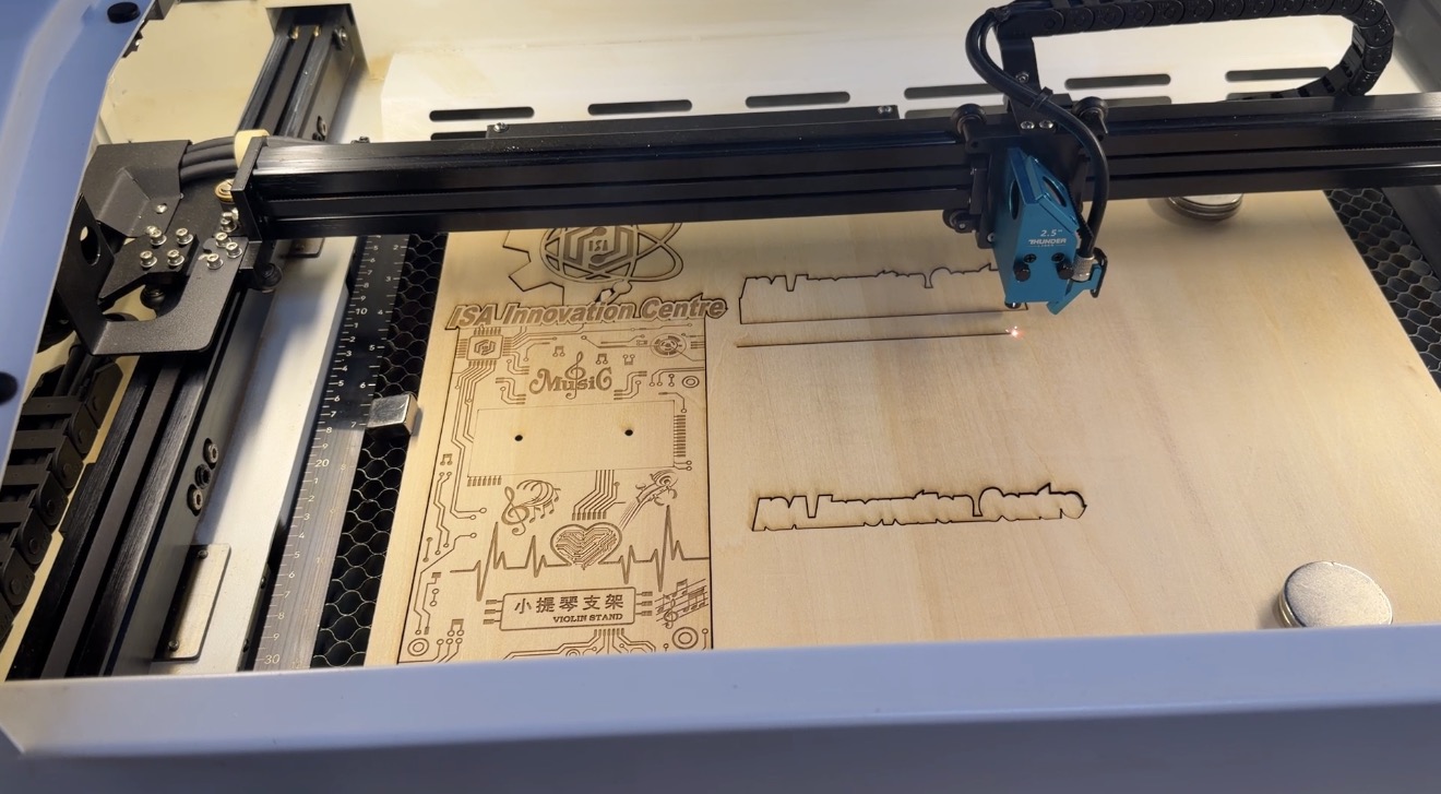
Machine pass, video and still on the LaserMaker bed
I ran the lab’s laser with our usual focus / power / speed recipe for the sheet thickness, engraving before through-cuts so small islands do not lift early. The short clip is sped-up proof of the job; the still shows the panel on the honeycomb in context.
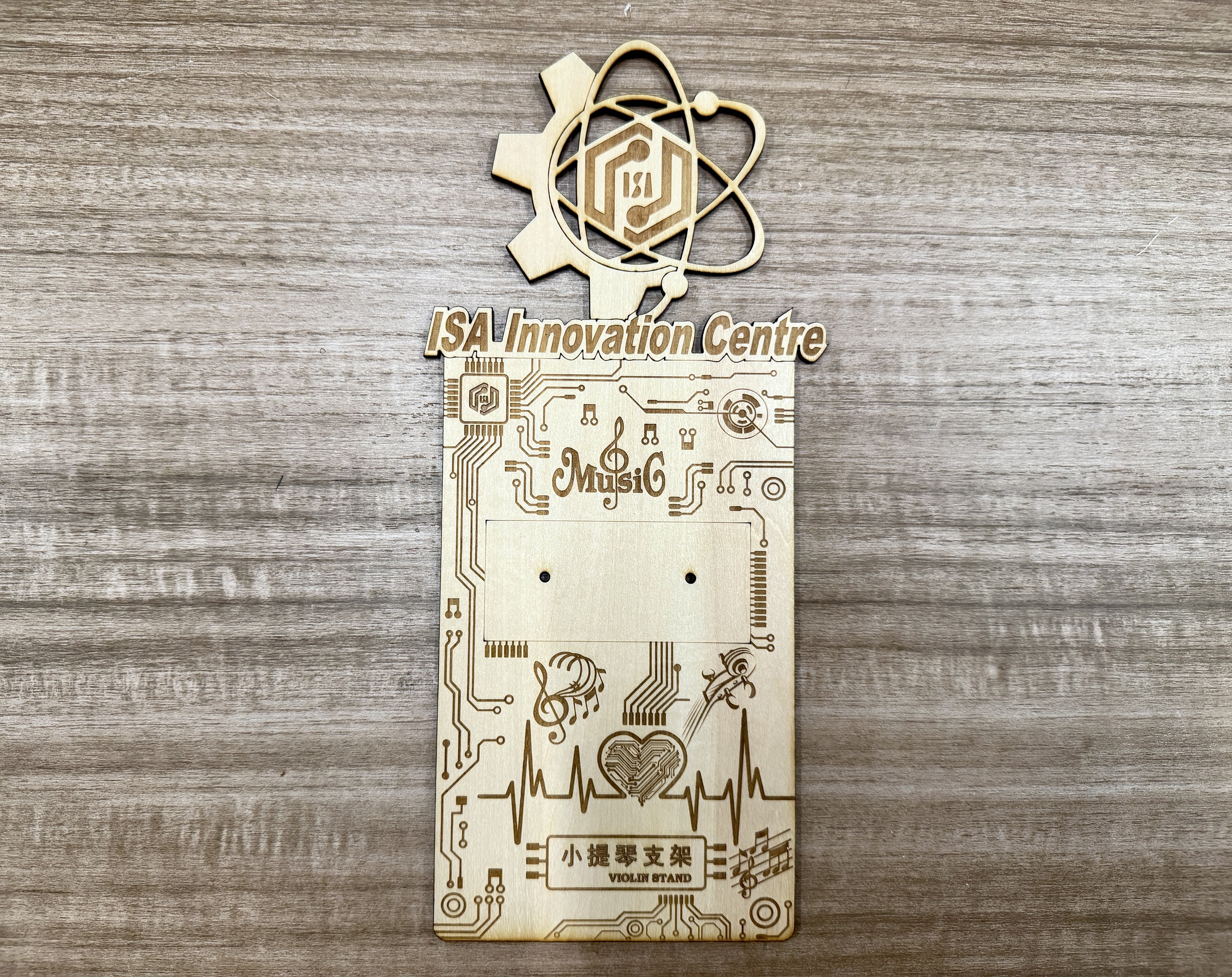
Post-processing: off the laser, hardware, clearcoat
Right off the bed the panel was warm and smoky; I brushed off char without sanding through shallow engraving. I mounted the metal bracket hardware through the prepared slots so I could trust alignment before painting. Then I misted clear acrylic as a dust seal, light coats so the grain still reads but fingerprints and graphite from handling do not embed in the texture.
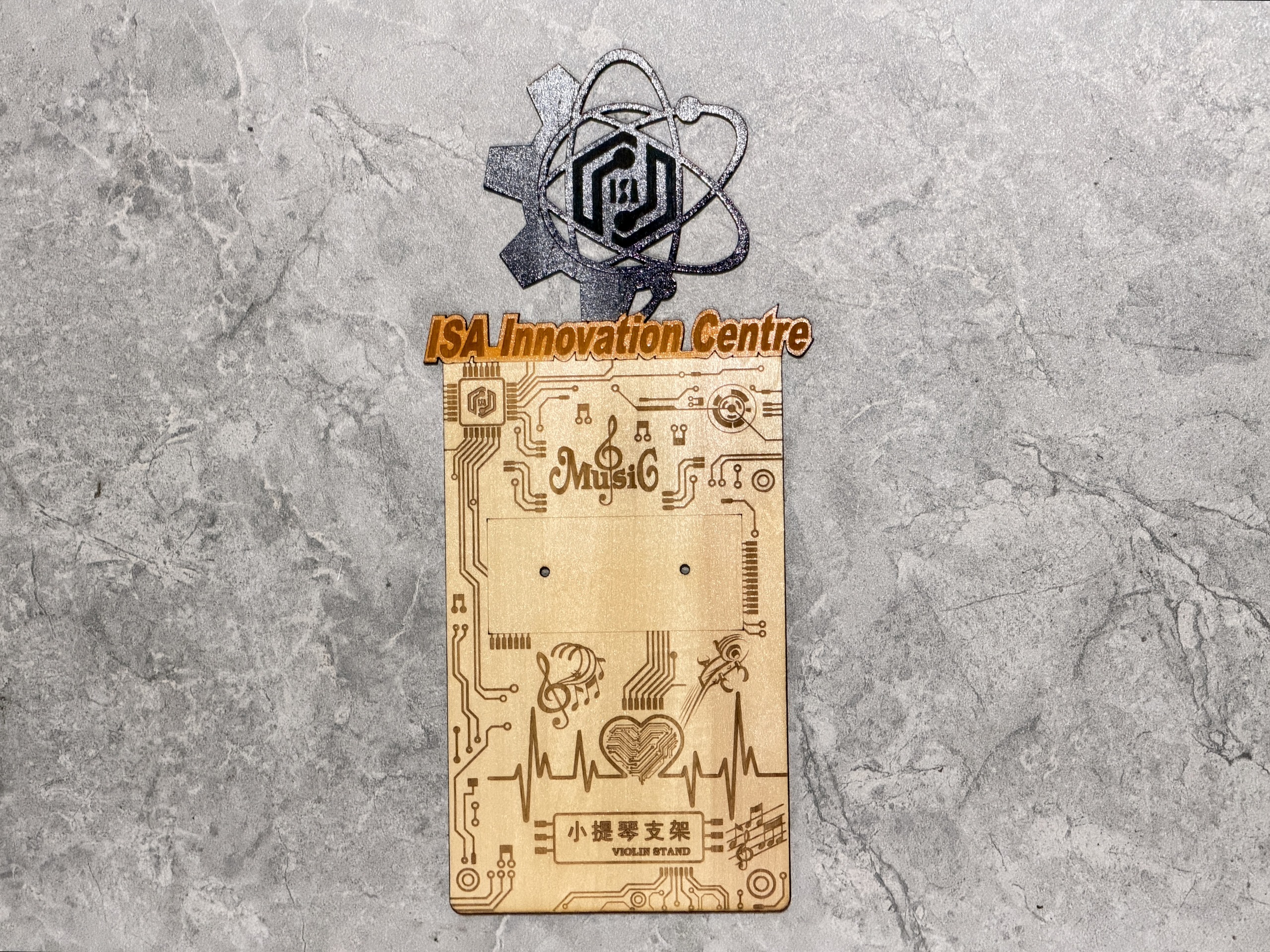
Masked spray: orange (mask 1), then black (mask 2)
With the laser-cut mask inserts taped flat, I shot orange through the first opening set, peeled, aligned mask 2, then laid down black. Keeping coats light avoided bleed-under at mask edges; anywhere the tape lifted, I paused and re-sealed before continuing. The physical mask pieces themselves are shown for transparency; they use the same geometry as design step 4.
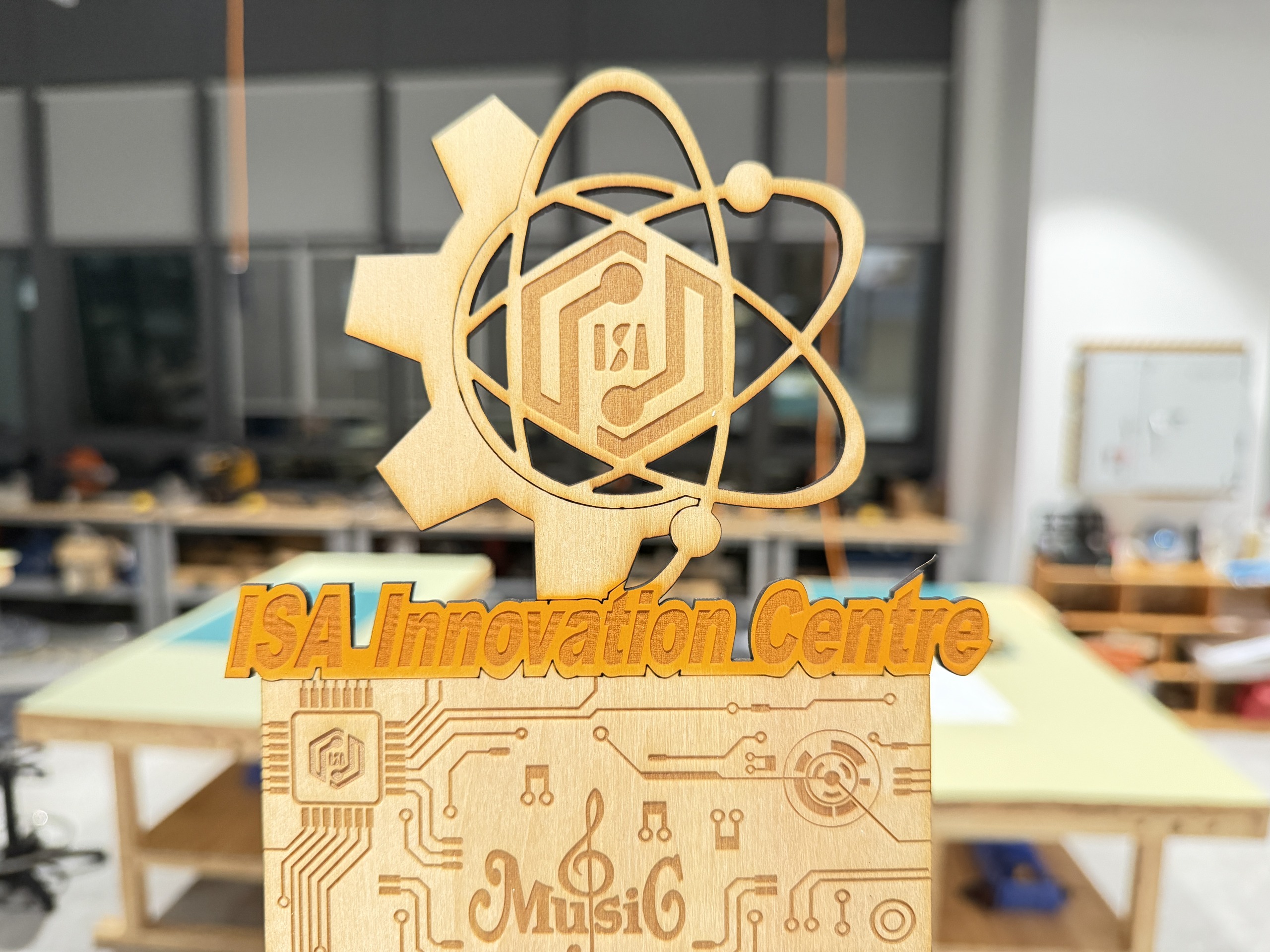
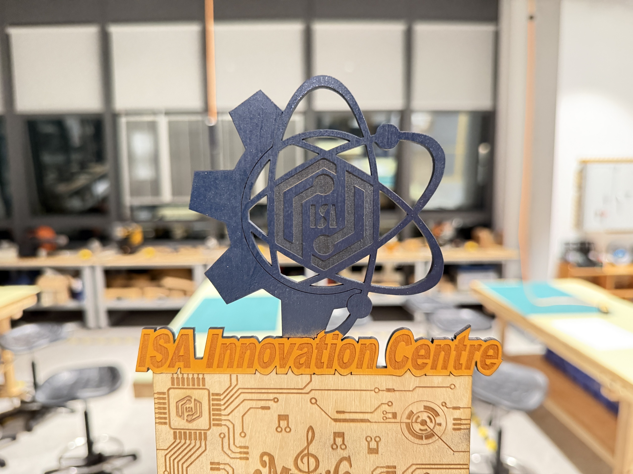
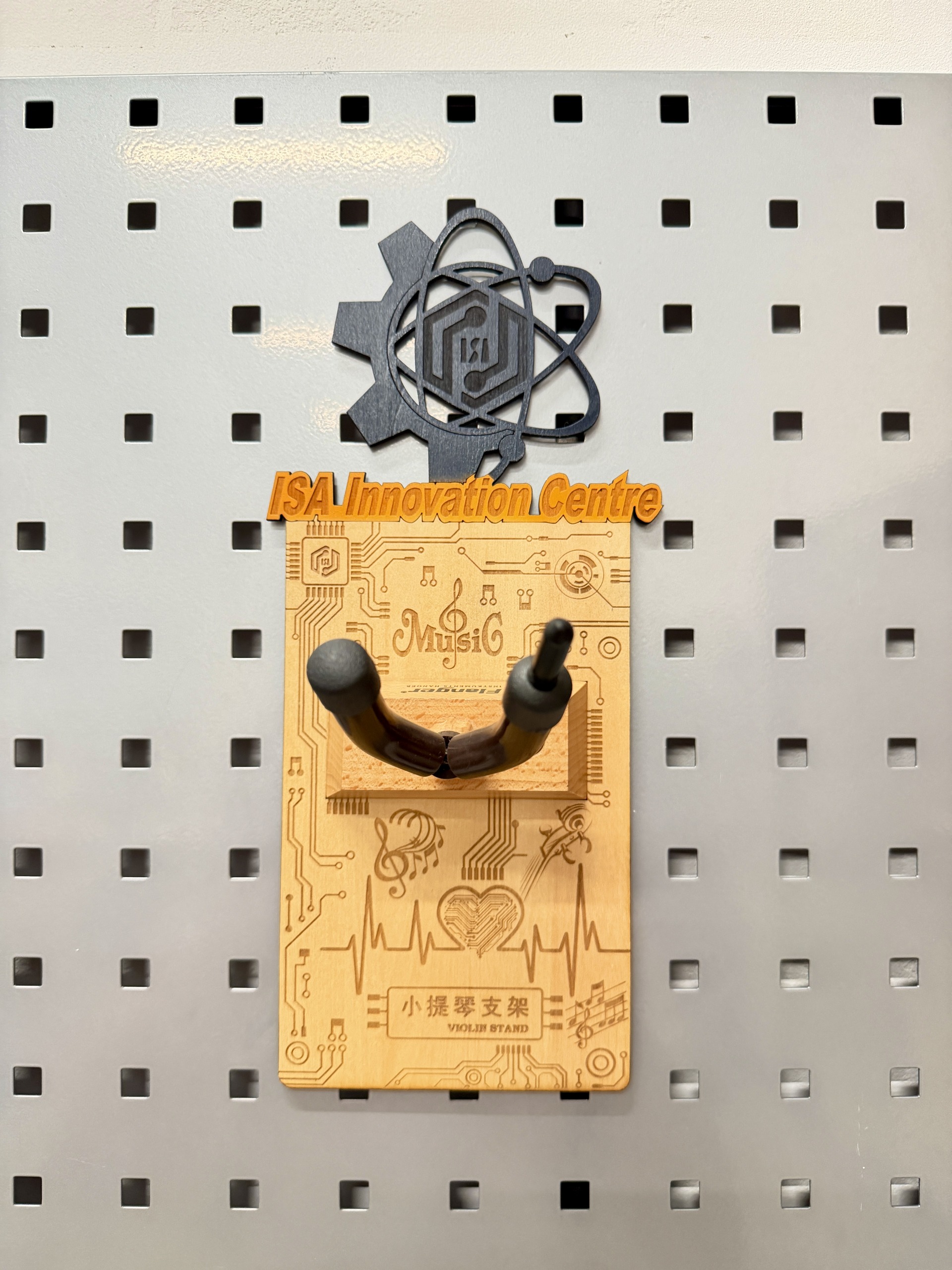
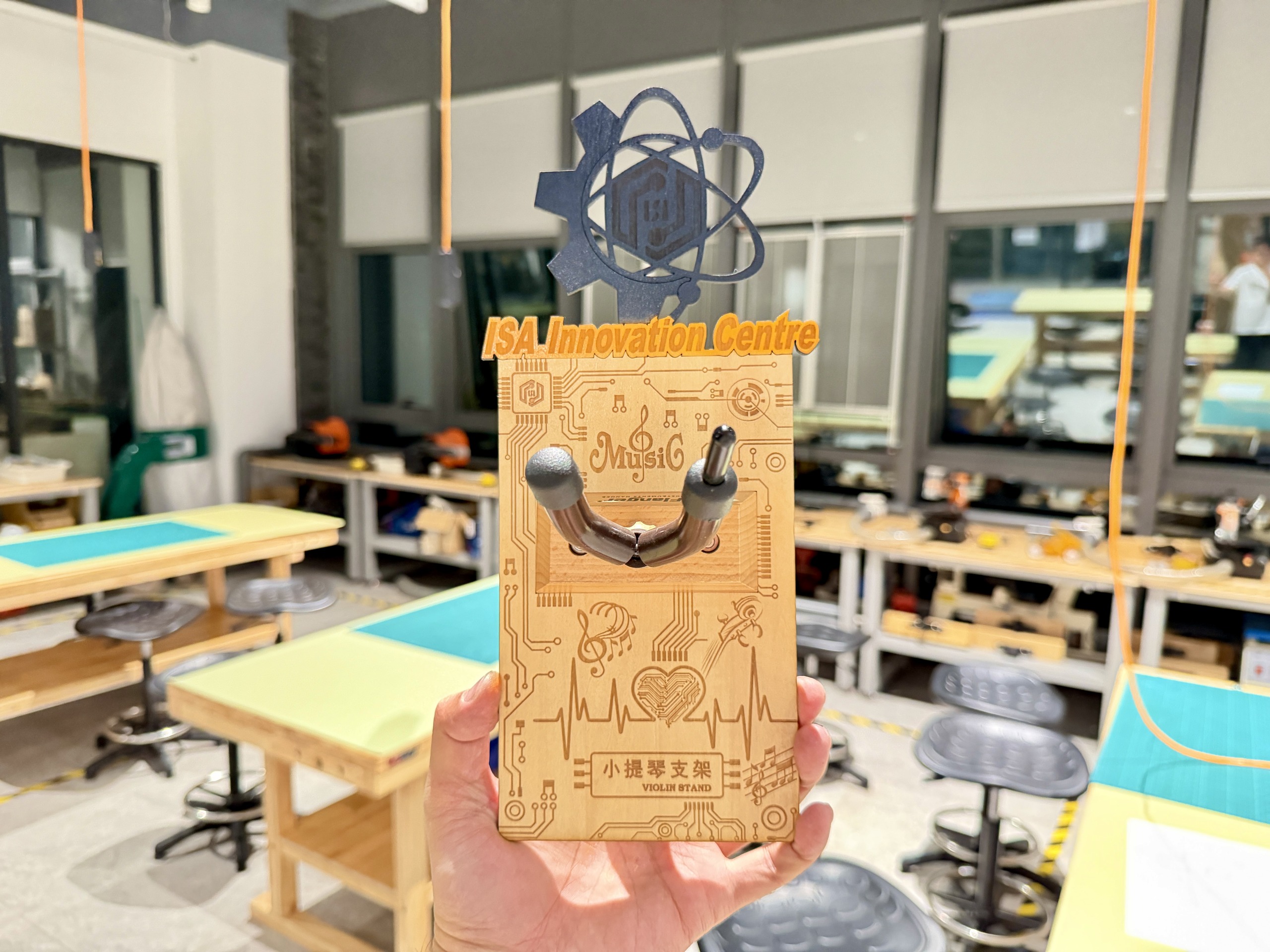
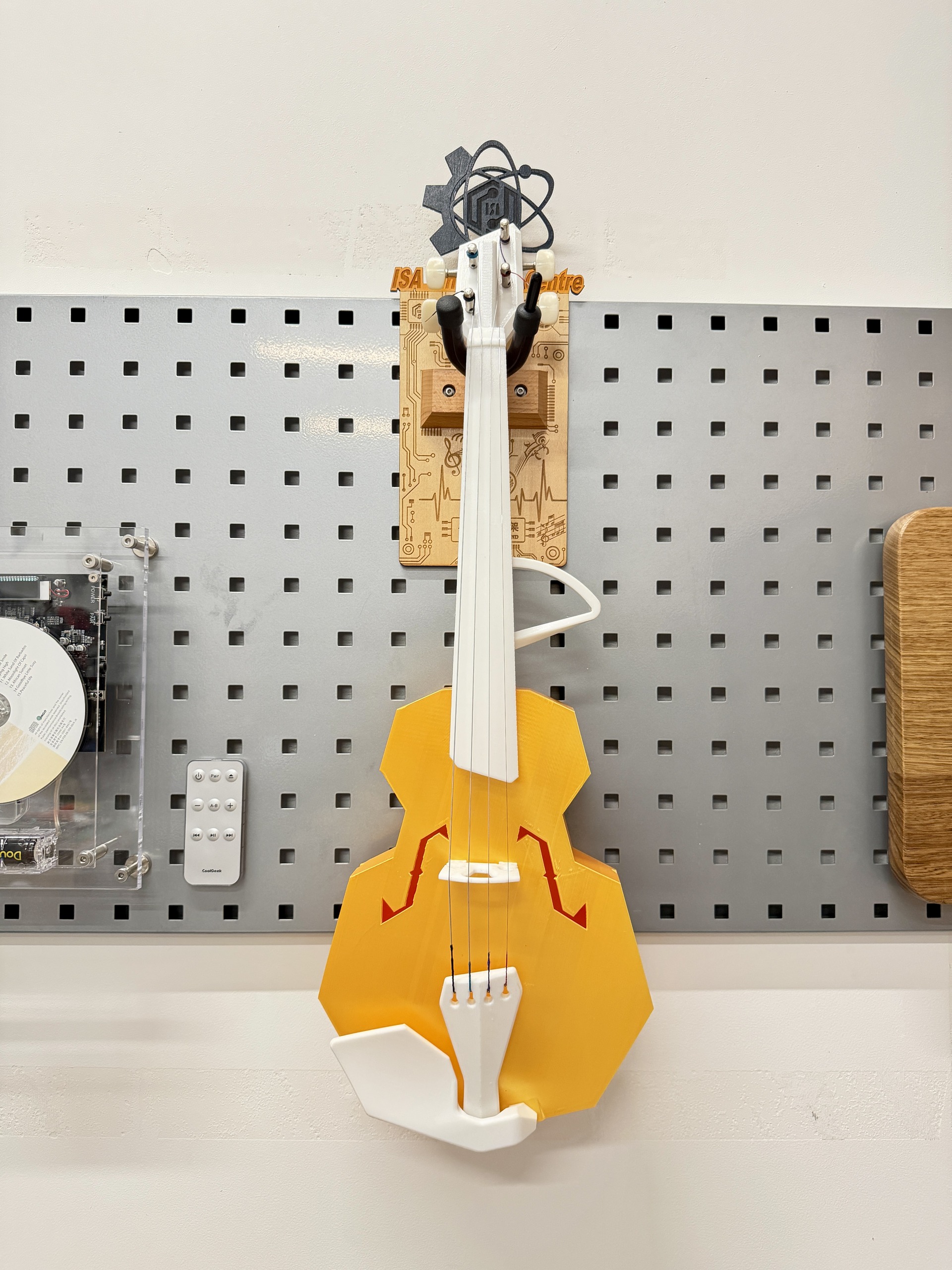
Finished piece and in-use context
The last photos are what I’d submit as evidence the loop closes: a finished bracket close-up and a wider scene showing how it reads on the wall next to other lab work. I still owe a tidy table of power / speed / kerf for this specific plywood lot. That is the next spreadsheet pass when I sync with our group characterization sheet.
Design files (download)
Both projects are native LaserMaker (.lcpx) archives, the same format as in the workflow above,
so anyone with LaserMaker can open layers and CAM settings intact. I host copies here so reviewers don’t
depend on my laptop; if you only need geometry, exporting SVG/DXF from LaserMaker is also possible, but the
live assignments use .lcpx.
How to fetch them from this site: click a link below → if the browser previews XML/text,
use Save As… (or right-click → Download linked file) so the file lands
as .lcpx → open in LaserMaker → point the machine profile at the lab cutter. On GitLab Pages,
“open instead of download” is common; saving explicitly avoids a corrupted workflow bundle.
Both projects are native LaserMaker (.lcpx) archives. I host copies here so
reviewers do not depend on my laptop. The
main Elsa tech violin layout
is the full bracket plus spray masks; the
music-symbol motif library
is the reusable clip-art shelf for notes and staffs. Splitting ornament from final panel is
how I actually iterate. If the browser previews XML instead of downloading, use Save As so the
file lands as .lcpx.
3D CAD (Blender): root planter & omni-wheel base
Following final-project.html and the repo’s
final-project-weekly-plan.md, this block documents Week 2 CAD where the main structure becomes
geometry I could actually print: how the planter meets the base, where cables run, and whether parts clash.
This step supports Milestone 1 (mobile platform and basic safety).
3D software choice: I used Blender for all steps below: mesh import, edit
mode cleanup, modifiers (taper, booleans), and STL export for the slicer. It is free / open source
and cross-platform, which made it easy to iterate on the same .blend between lab machines and my
own computer. Official installers and release notes live on the project download page:
Blender — Download. Typical install:
choose the latest stable or LTS build → select operating system (macOS/Windows/Linux) → run the downloaded
package → on first launch, pick defaults suitable for “general” modeling and enable import/export add-ons if
needed for uncommon mesh formats.
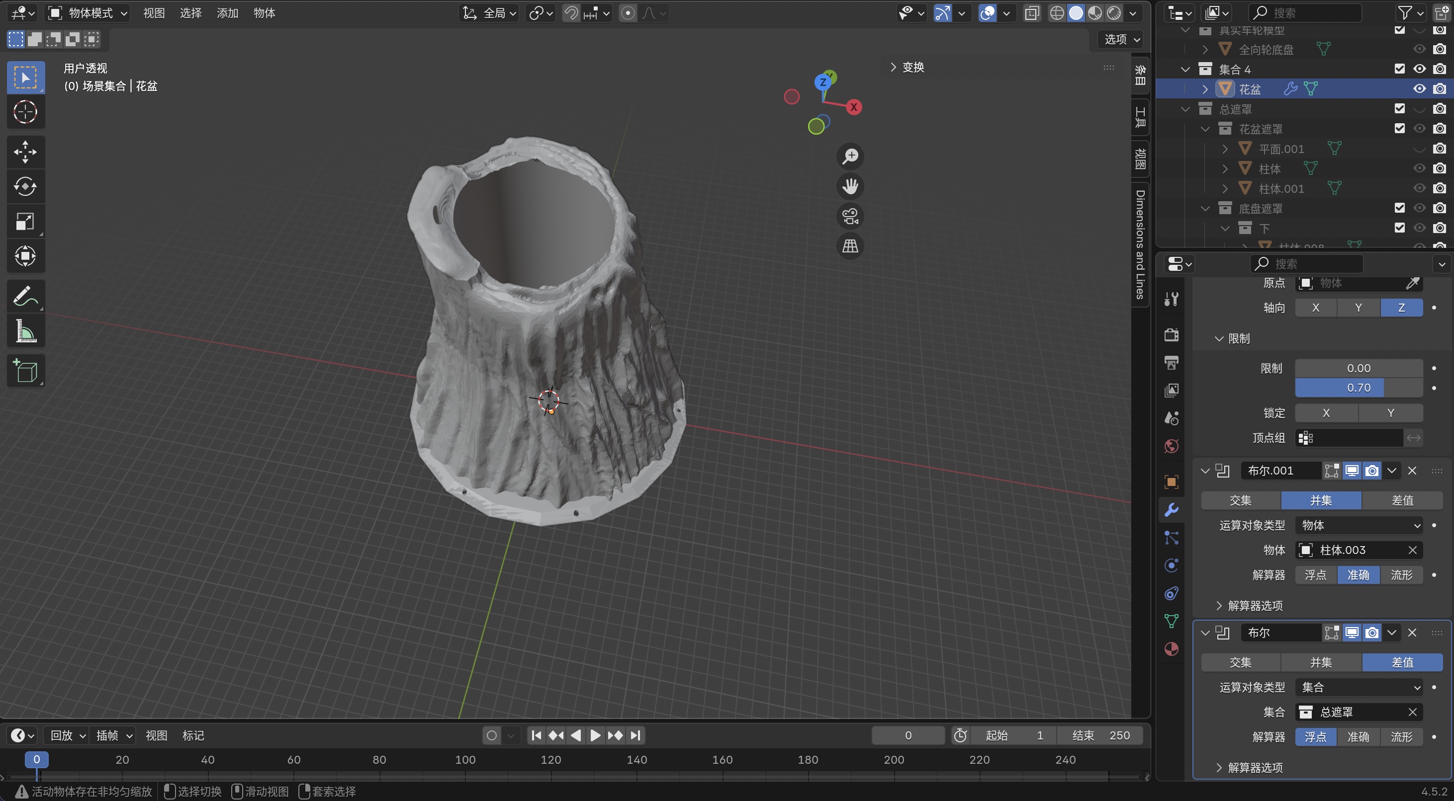
The practical order in Blender is an eight-step pipeline:
import mesh → adapt details → scale to the rover →
taper → bottom volume → mask solids →
boolean union (trunk + bottom) → boolean intersection / difference with masks
for wheel wells, routing, and fasteners. That order stabilized after
Week 5 showed the first full print failed when the root and wheel ring were not
a single watertight solid. The slicer bridged gaps instead of tracing shared perimeters. The captures below record
the workflow I use now. A one-line-per-step outline also lives in
documents/week05-modeling-process-outline.docx; file names in the repo follow the step/sub-step
pattern (for example 1.1, 2.3).
Blender, and why I used it
Blender is open-source 3D software: mesh modeling, modifiers (including booleans), and STL/OBJ import/export are enough for mixed organic-and-mechanical parts like this planter. The same official download page bundles the documentation and release highlights; I stayed on a recent stable build so modifier behavior matched what Week 5 used for the failed / reworked prints.
I used it mainly because the planter is an irregular organic surface from a downloaded mesh, and I needed the root and the wheel base in one scene to line them up, add a printable bottom, and cut openings without leaving floating shells. It is free and runs on my laptop, which helps for trial and error.
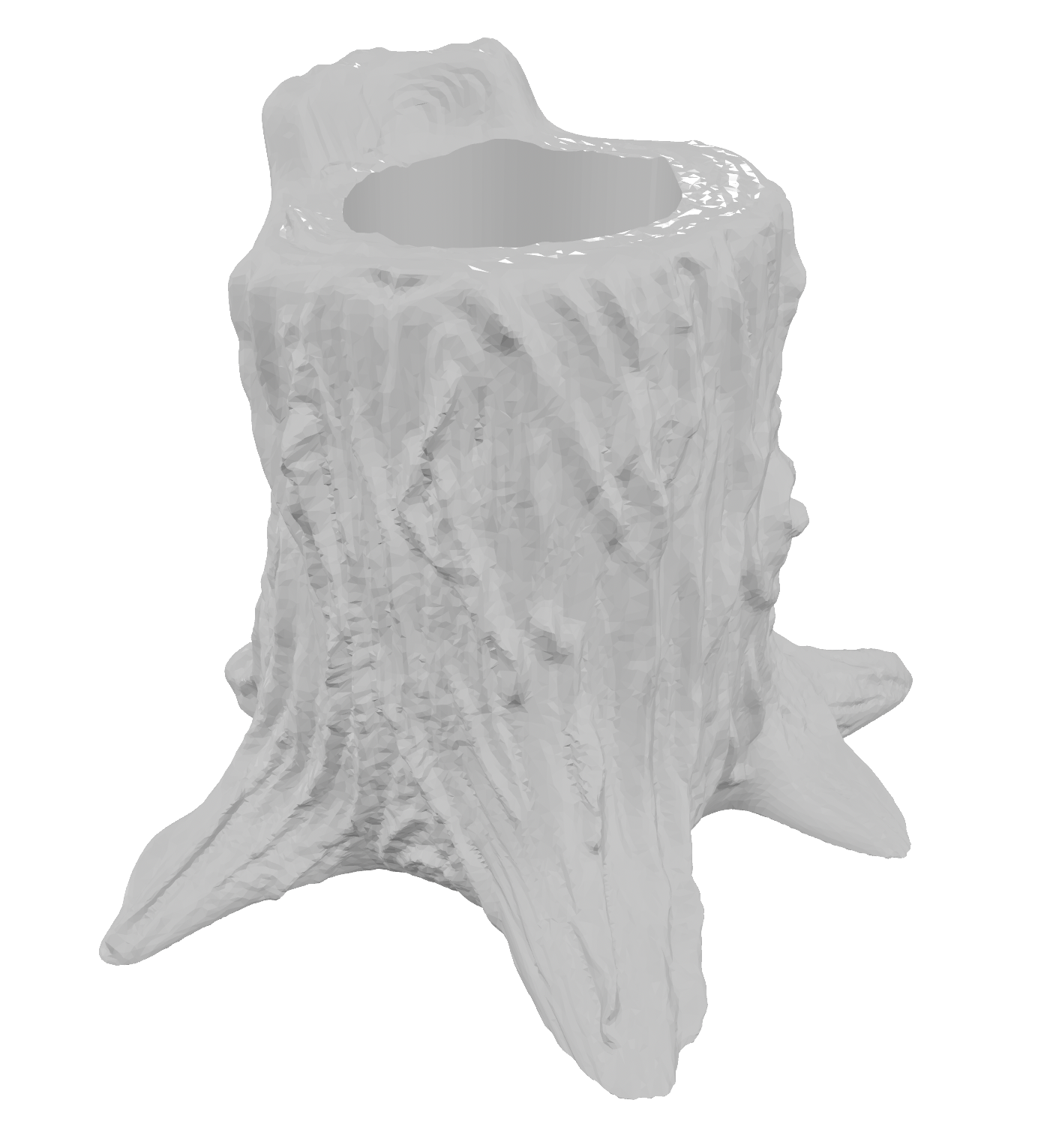
Open-source starting mesh
The planter starts from an open-source root “pencil holder” mesh (same asset family as in the steps below). Figure 15 shows the source listing / provenance I kept for the assignment.
Choosing and downloading the base file: on the repository page I checked the
license (e.g. Creative Commons / explicit commercial-use OK) and the file format
, I picked a mesh I could import with Blender’s File → Import (commonly .stl,
.obj, or .fbx). Download steps are usually: sign in if the site requires it → click
Download → save into my project folder with a clear filename → in Blender,
File → Import → … and scale/orient once in the viewport. I chose this particular stump/holder
because the silhouette already reads as a planter, the cavity fits the “root” story for the
final project, and starting from a sculpt saved days of blocking organic bark that weren’t the learning goal for
Week 2 (booleans against the rover base were).
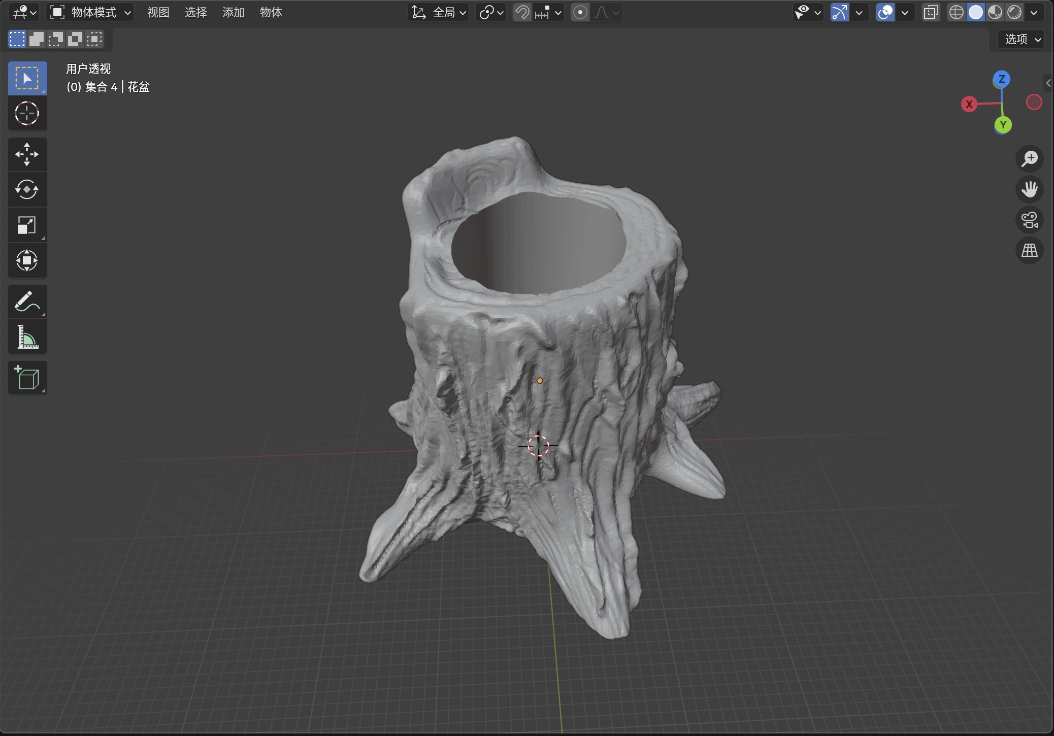
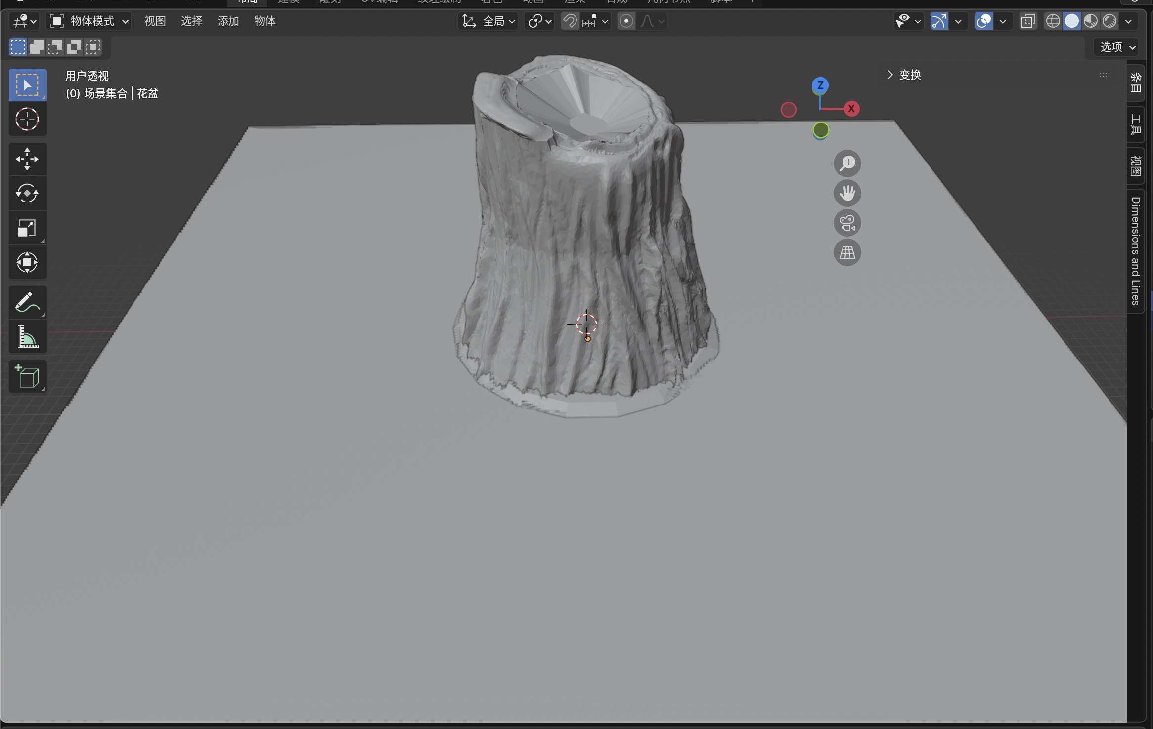
Step 1: Import the trunk pencil-holder model
With the downloaded file from the listing (see Open-source starting mesh), I used Blender’s File → Import menu and the appropriate entry for the format I saved (for example STL or Wavefront (.obj)). That brings the trunk in as the starting body, staged for a print-ready assembly, not only a render prop, centered and scaled roughly before the first cleanup pass.
Step 2: Adapt and refine details
I adapted the mesh and edited fine detail so the organic shell could take the later taper, masks, and booleans without self-intersections, pinholes, or knife-edge walls that FDM cannot reproduce.
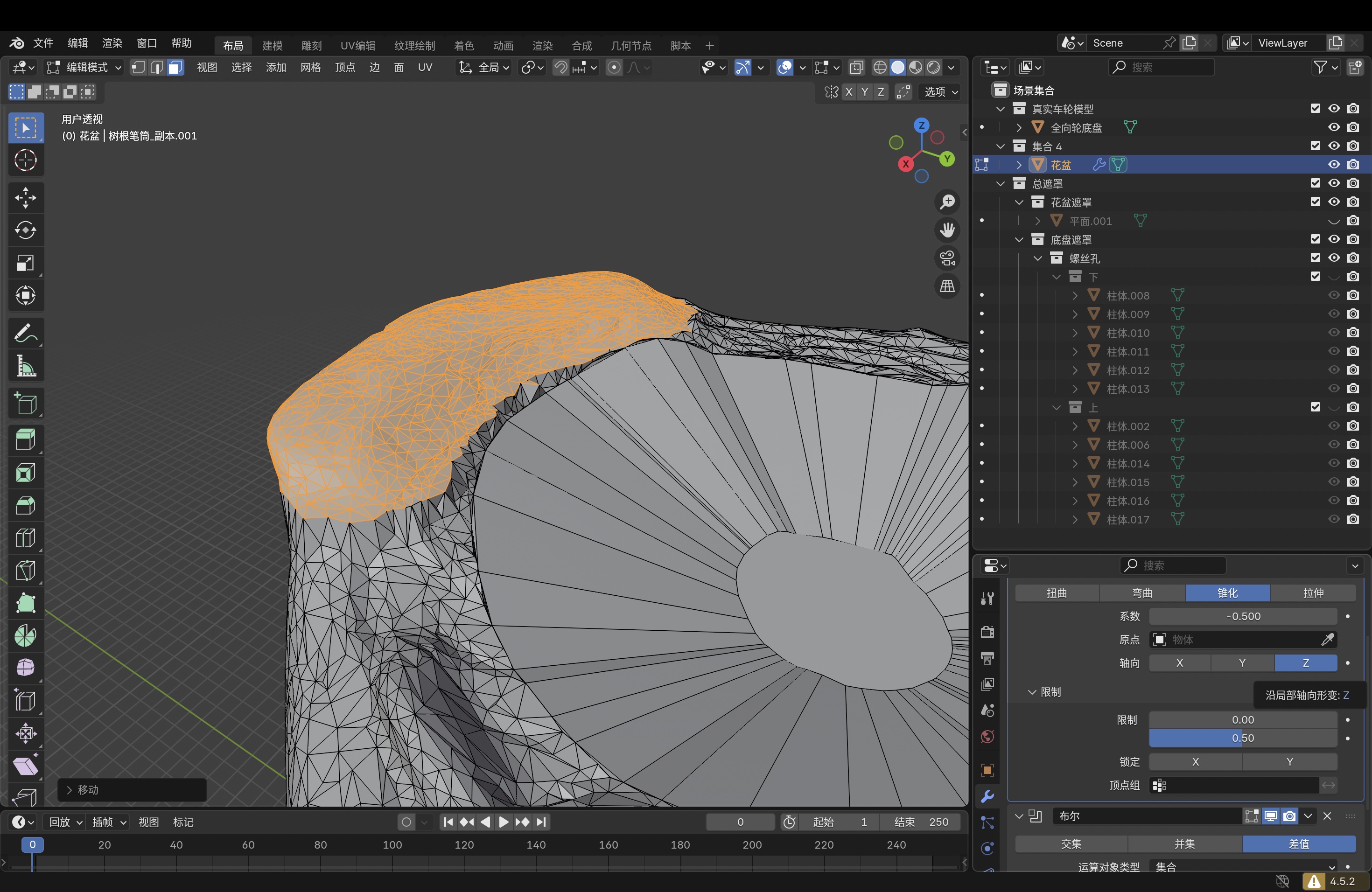
Step 3: Resize the trunk to match the rover
I scaled the trunk to the omni-wheel plate and chassis so wheel pockets, cable exits, and mounting features lined up with the mobile base in one assembly.
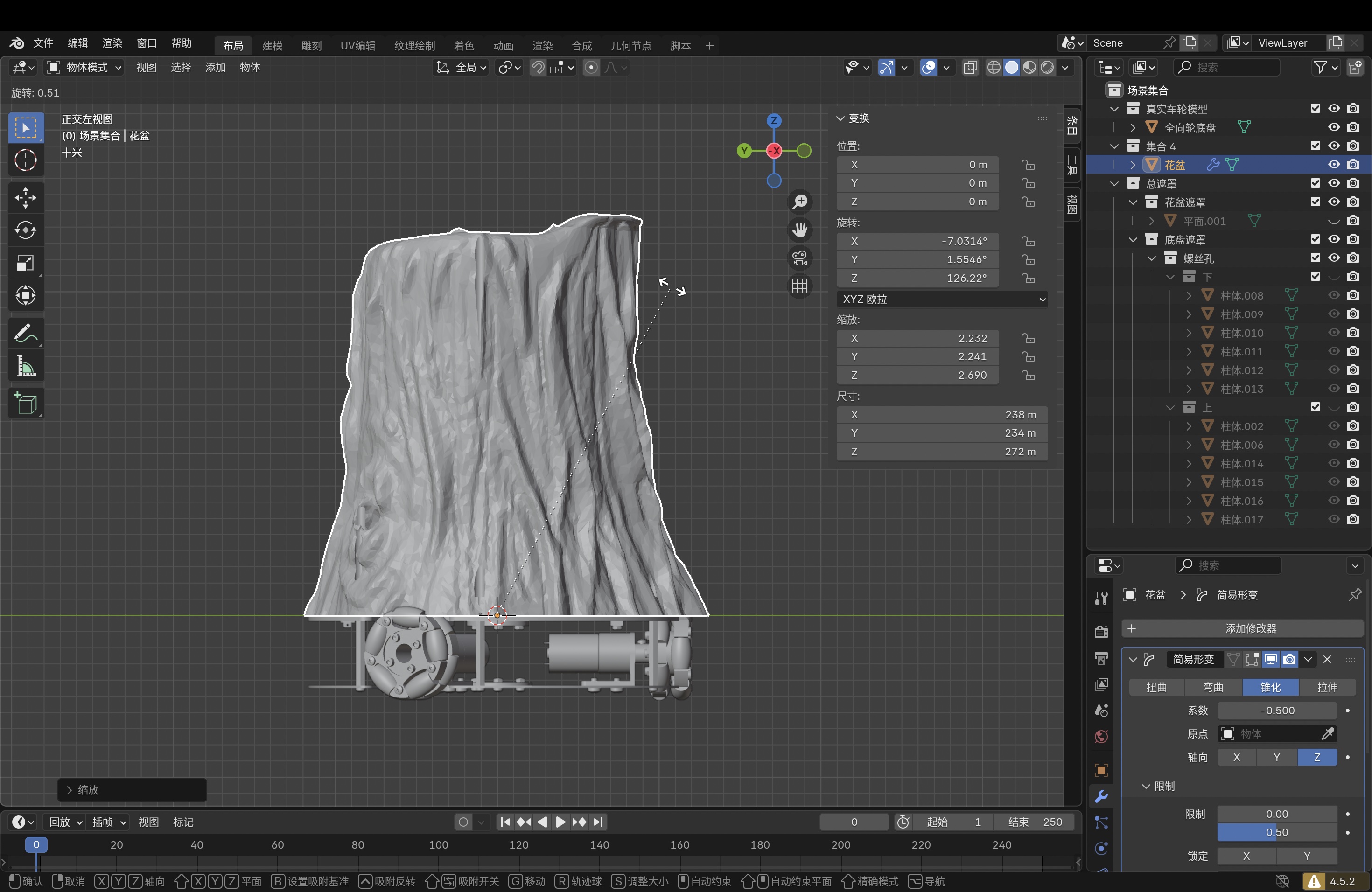
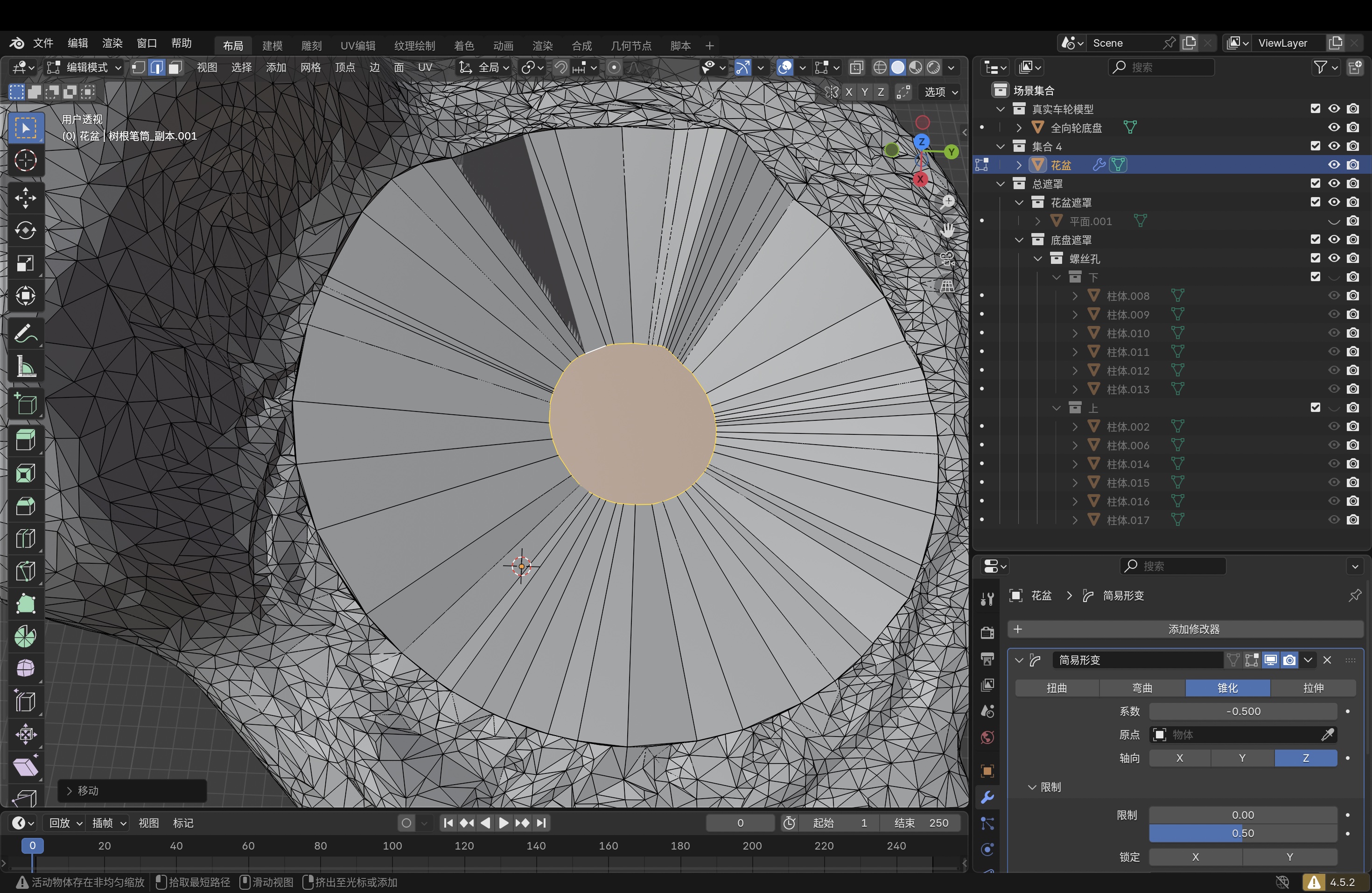
Step 4: Add the taper modifier
I added Blender’s Taper modifier and tuned it so the trunk silhouette fit the rover footprint, narrowing or flaring the mesh before the bottom and masks were merged in.
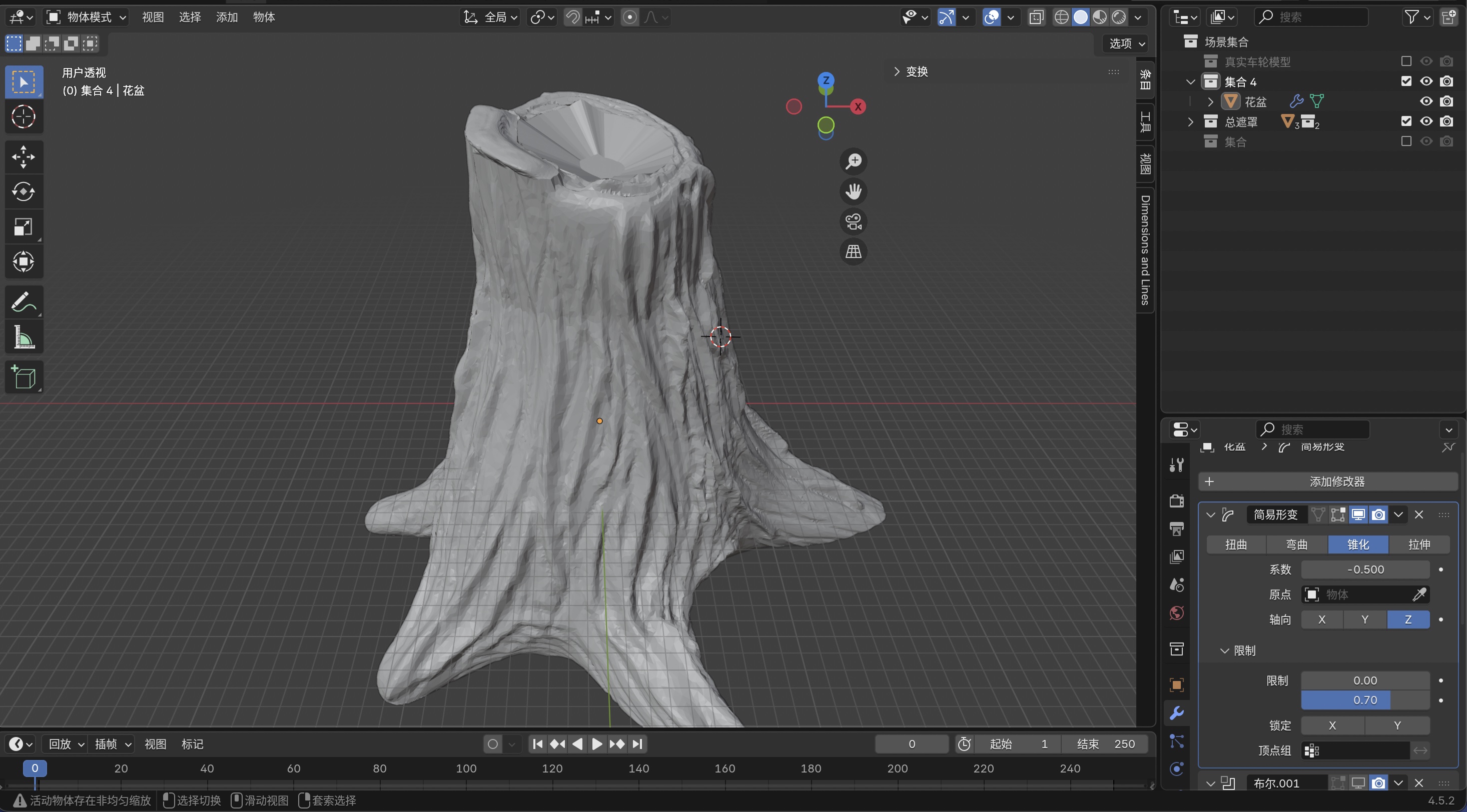
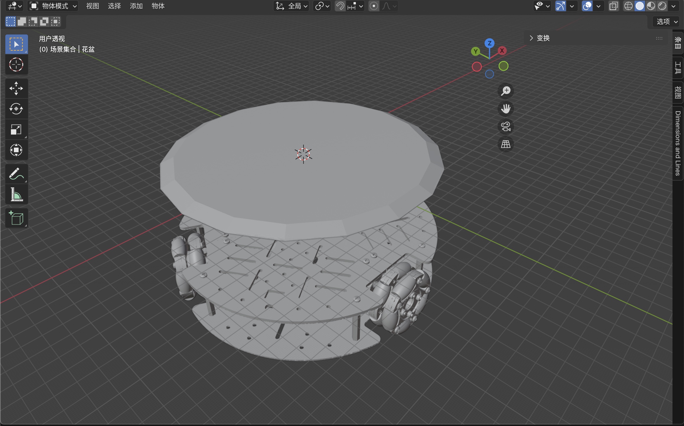
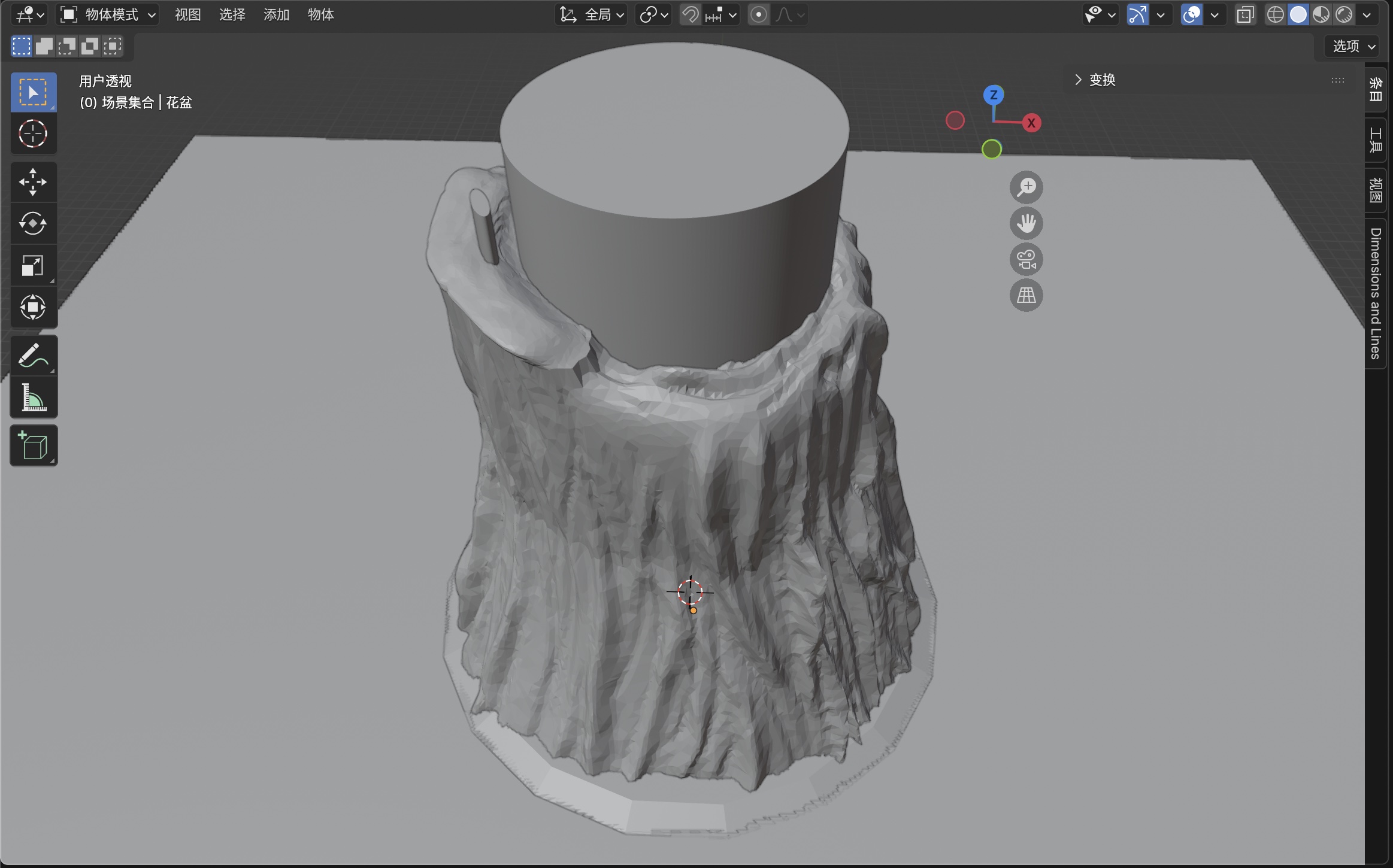
Step 5: Add the bottom to match rover and trunk scale
I modeled a bottom volume sized to both the rover plate and the trunk so the flat platform and the organic shell met with solid contact. That was the main fix for a reliable FDM joint instead of a long air bridge in the slicer.
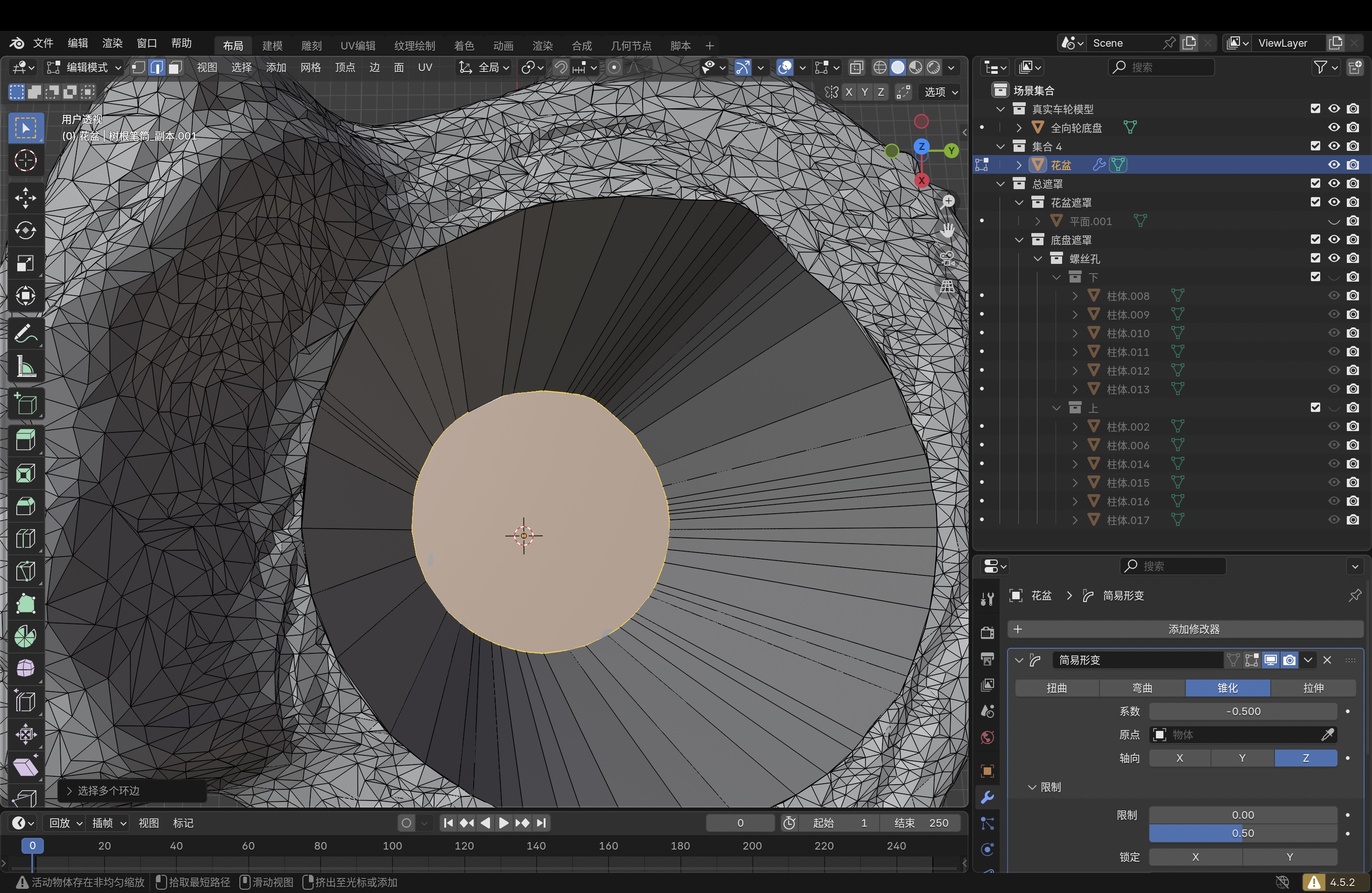
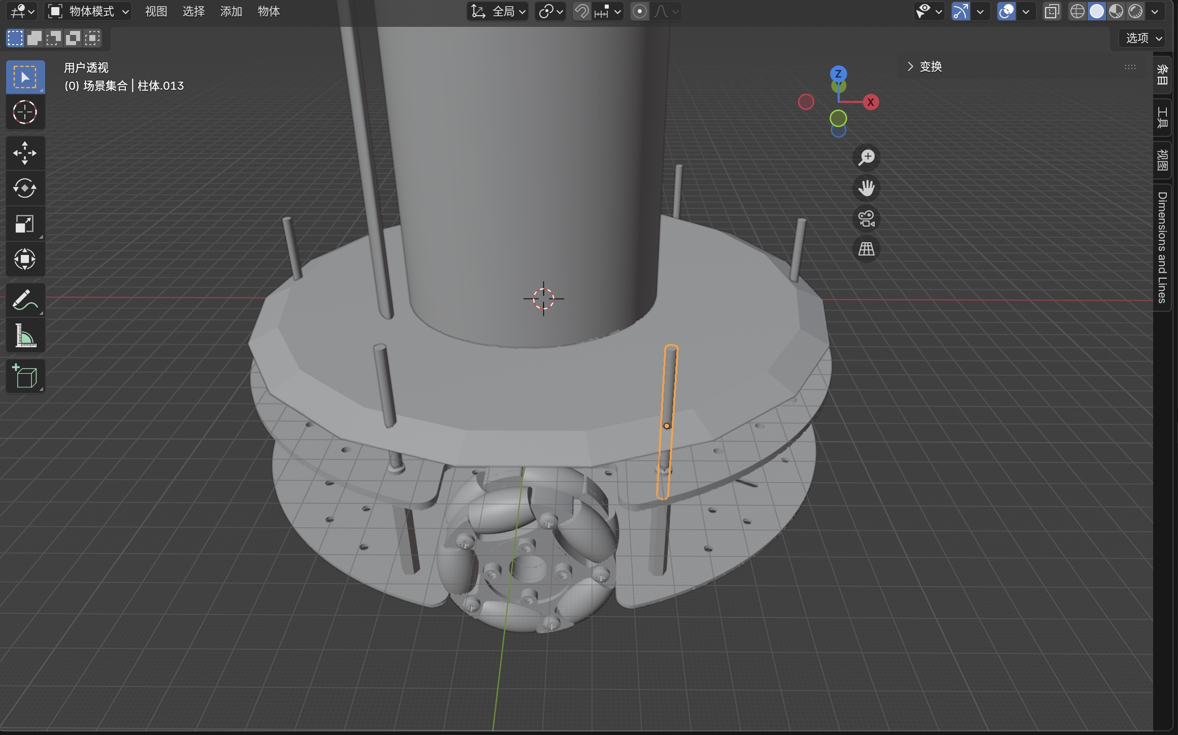
Step 6: Add masks for the various cuts
I added separate mask solids (helpers for wheel pockets, routing holes, and clearance cylinders) so each feature could be driven with predictable booleans instead of ad hoc mesh edits alone.
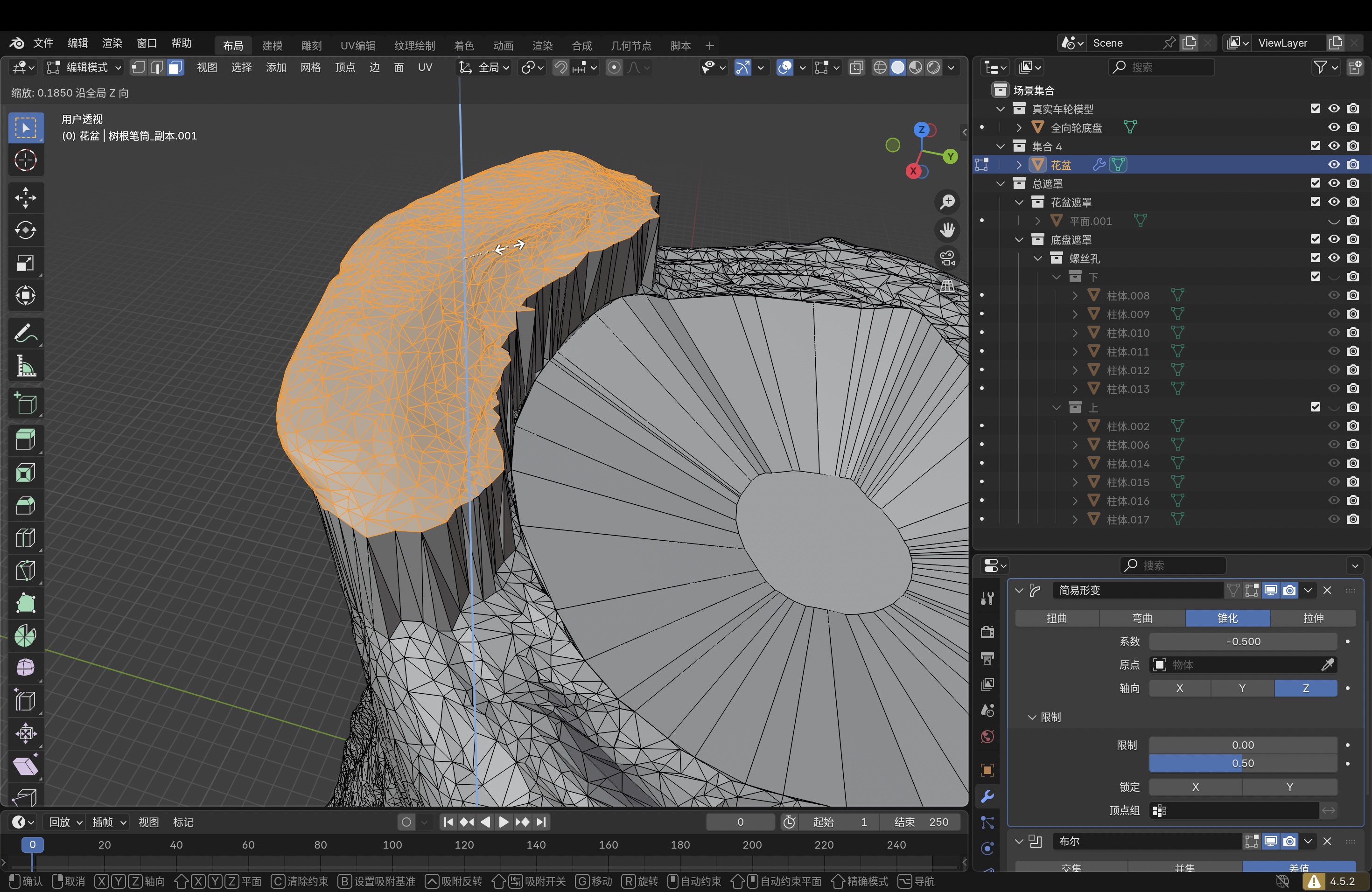
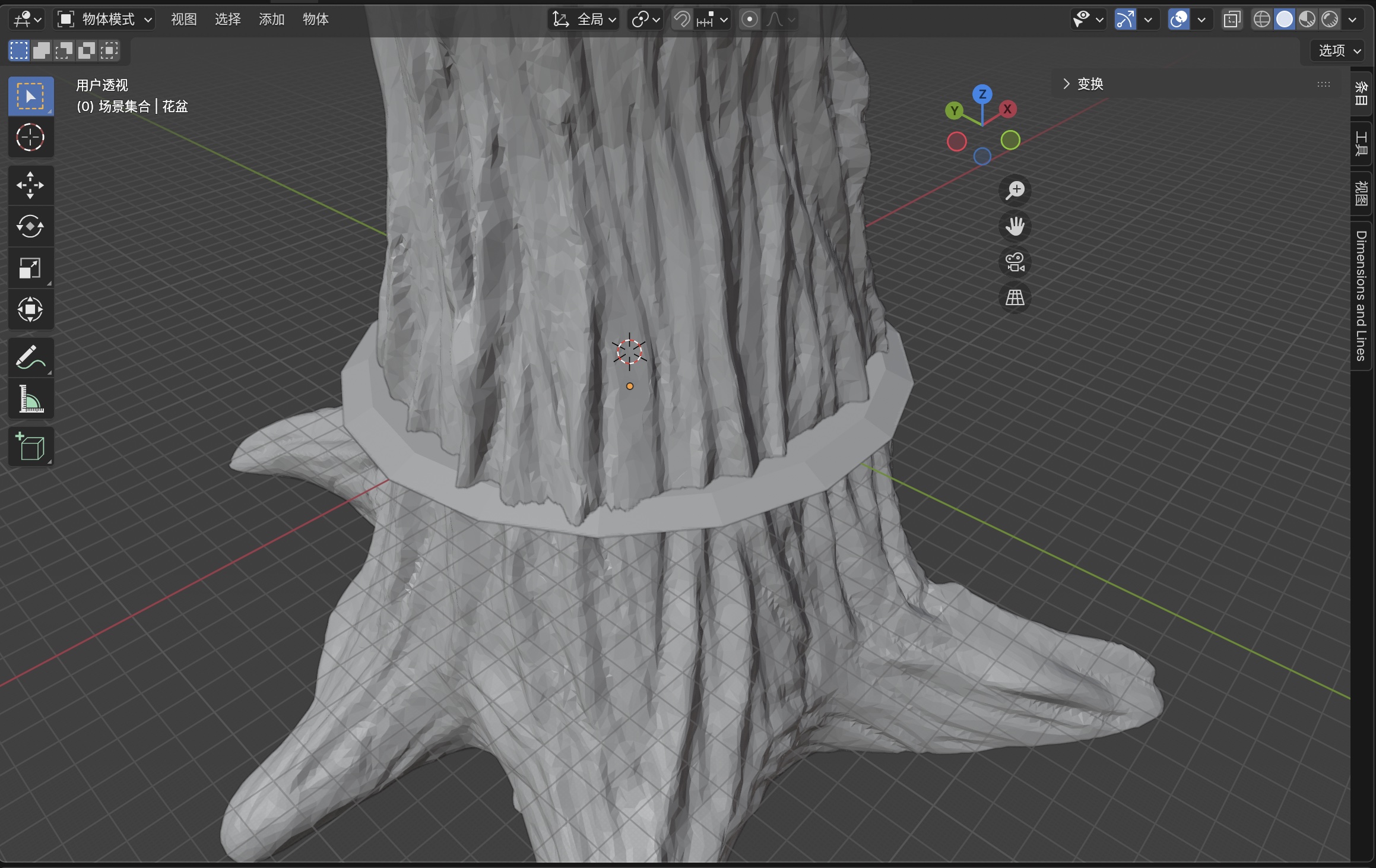
Step 7: Boolean union: trunk and bottom
I applied a boolean union so the trunk and bottom became one watertight solid for export. That directly addressed the weak root-to-base junctions I saw in slicing.
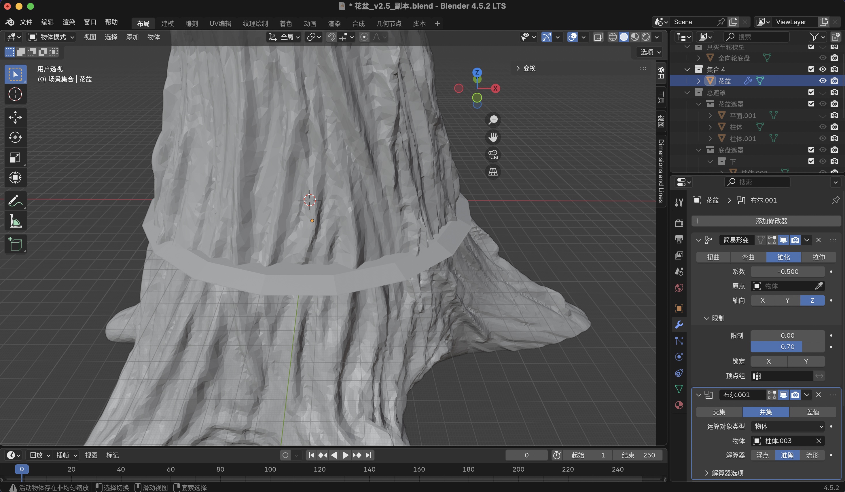
Step 8: Boolean intersection: trunk and masks
I used boolean intersection (and difference where needed) so the mask volumes carved the final openings (wheel wells, cable path, fastener holes) without leaving non-manifold or floating fragments in the exported mesh.
Final Blender source file
The final Week 2 Blender drawing is my planter model with the hand-shaped chassis/base
included. The raw .blend is about 144 MB; zipping it shrinks the download to
about 57 MB, but Fab Academy GitLab still rejects any single push larger than roughly
50 MiB, so I split the zip into two parts. Download
part 1 (~40 MB)
and
part 2 (~17 MB),
then follow the restore steps below.
How to restore the split archive (复原教程)
Anyone cloning this assignment should end up with the same 花盆_v3.2.blend I used in lab. The parts are
not two different models; they are one zip file cut in half for upload. You need both parts in the
same folder before merging.
Step 1 — Download both parts
Click each link above (or right-click → Save Link As…). Put
花盆_v3.2.blend.zip.part-aa and 花盆_v3.2.blend.zip.part-ab in one directory, e.g.
design-files/week02/ on your machine. If either file is missing, the merge will produce a broken zip.
Step 2 — Merge the parts into one zip
macOS or Linux (Terminal): open Terminal, cd into the folder that holds both parts, then:
cd path/to/design-files/week02
cat 花盆_v3.2.blend.zip.part-* > 花盆_v3.2.blend.zip
ls -lh 花盆_v3.2.blend.zip
The merged file should be about 57 MB. If it is only ~40 MB, part-ab is probably still missing or
was not included in the cat command.
Windows (Command Prompt): open cmd, cd to the folder with both parts, then:
cd path\to\design-files\week02
copy /b 花盆_v3.2.blend.zip.part-aa+花盆_v3.2.blend.zip.part-ab 花盆_v3.2.blend.zip
Windows (PowerShell): same folder, then:
cd path\to\design-files\week02
Get-Content -Path "花盆_v3.2.blend.zip.part-aa","花盆_v3.2.blend.zip.part-ab" -AsByteStream |
  Set-Content -Path "花盆_v3.2.blend.zip" -AsByteStream
Step 3 — Unzip to get the Blender file
Double-click 花盆_v3.2.blend.zip in Finder or Explorer, or from a terminal:
unzip 花盆_v3.2.blend.zip
You should see 花盆_v3.2.blend (~144 MB). Open it in
Blender (File → Open). The same
version I used is fine; Blender generally opens older .blend files forward-compatible.
Step 4 — Quick sanity check
In the Blender viewport I expect the planter trunk, tapered shell, bottom platform, and mask objects from the eight-step pipeline above. If the file fails to open or reports corruption, re-download both parts (a partial download is the usual cause) and repeat the merge. Do not rename the part files before merging.
I kept the unsplit .blend and full zip on my laptop for local edits; only the two part files live on
GitLab so the class site stays within the upload limit.
What’s on this page and what’s next
Week 2 individual work covers the Elsa tech–music violin bracket in LaserMaker (including the separate
music-symbol .lcpx), the machine run, and mask-guided spray, plus Blender CAD for the planter and
omni-wheel base (eight-step pipeline: import → detail → scale → taper → bottom → masks → union → intersection),
with the final .blend split archive linked above (see
restore steps to merge the two parts).
FDM validation is on Week 5: 3D scanning and printing.
Next: tabulate sheet thickness, power, speed, focus, and kerf for this plywood lot next to the
downloadable .lcpx files; keep versioning Blender sources as the rover hardware shifts; repeat the
mask workflow if I add a third accent color so registration stays predictable.
Website uploads: shrinking photos and clips
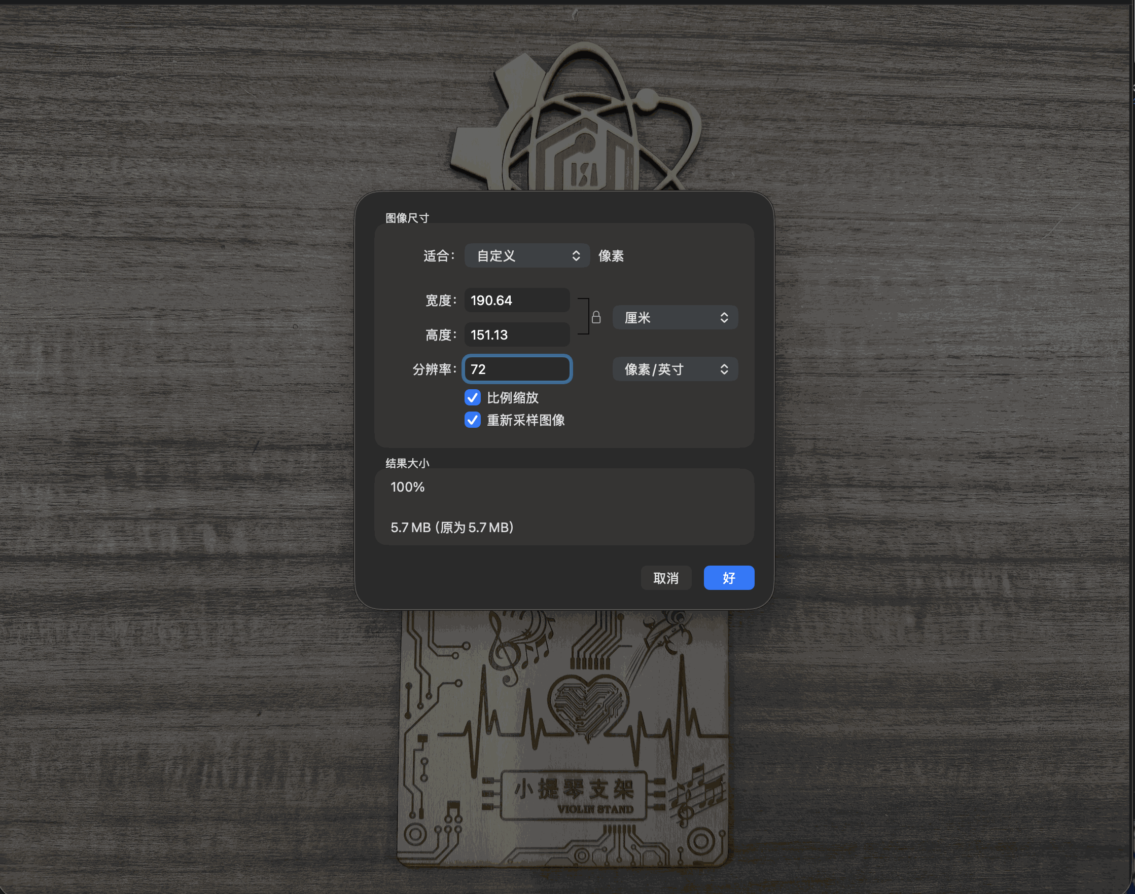
The class site/GitLab uploads cap how heavy each file can be, so before publishing I prepared smaller versions of the same screenshots and a screen recording. Two ideas I kept in mind: resolution sets how many pixels describe the scene, while JPEG export quality sets roughly how many bits encode each pixel. I used both controls in sequence on stills. For motion, exporting a lower-resolution movie from QuickTime is the simple built-in route on macOS when I only need proof of process, not mastering quality.
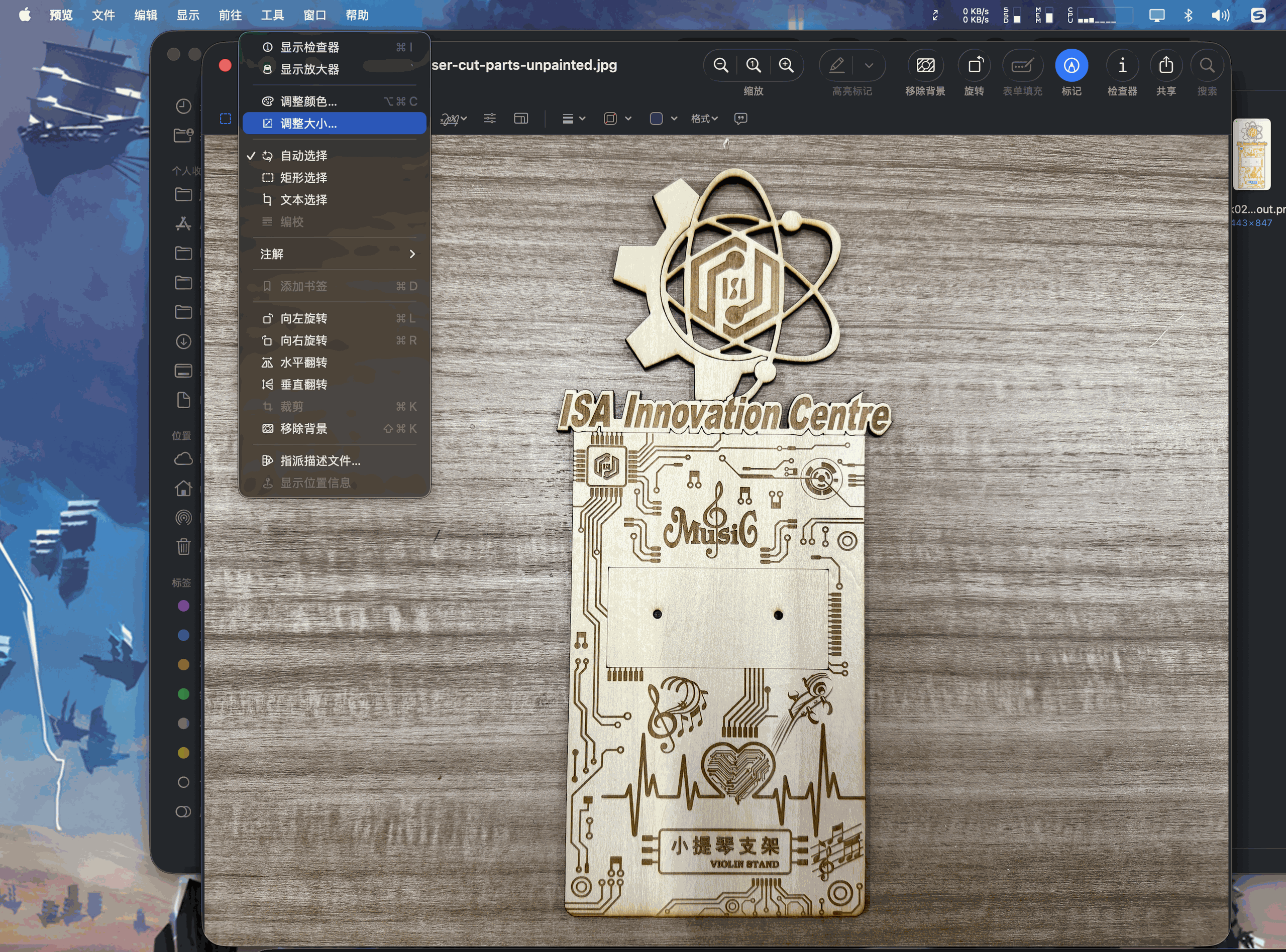
Images: Preview (adjust size → export JPEG)
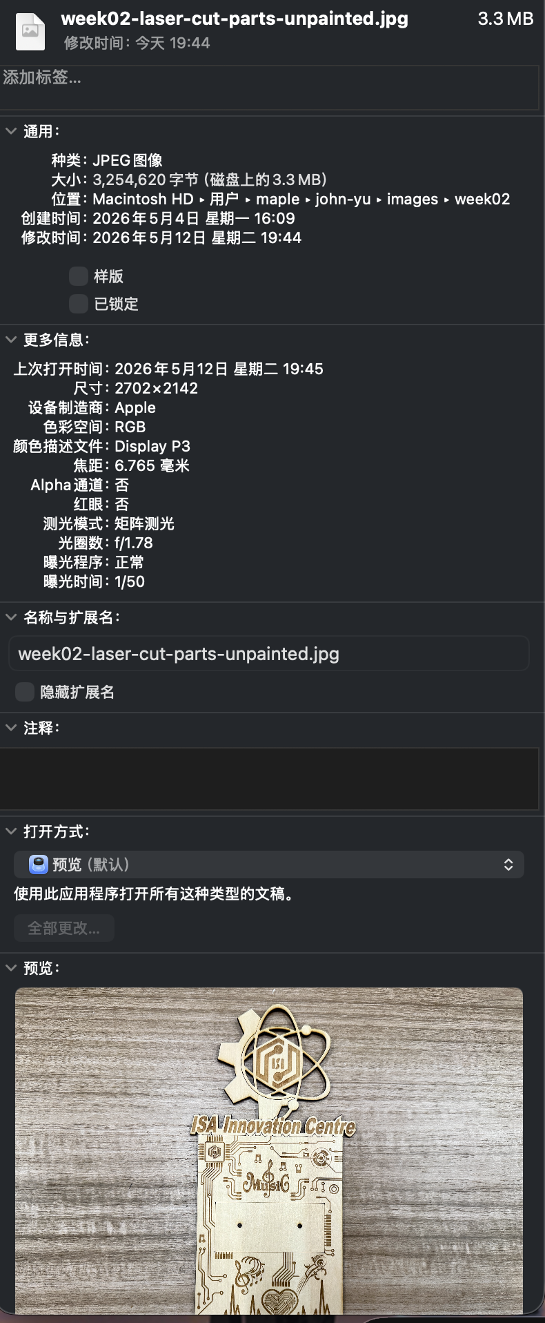
I duplicated my working files first, then in Preview used Tools → Adjust Size… with proportional scaling checked. I snapped Finder Get Info before and after so the assignment shows the shrink in MB, not only a guess.
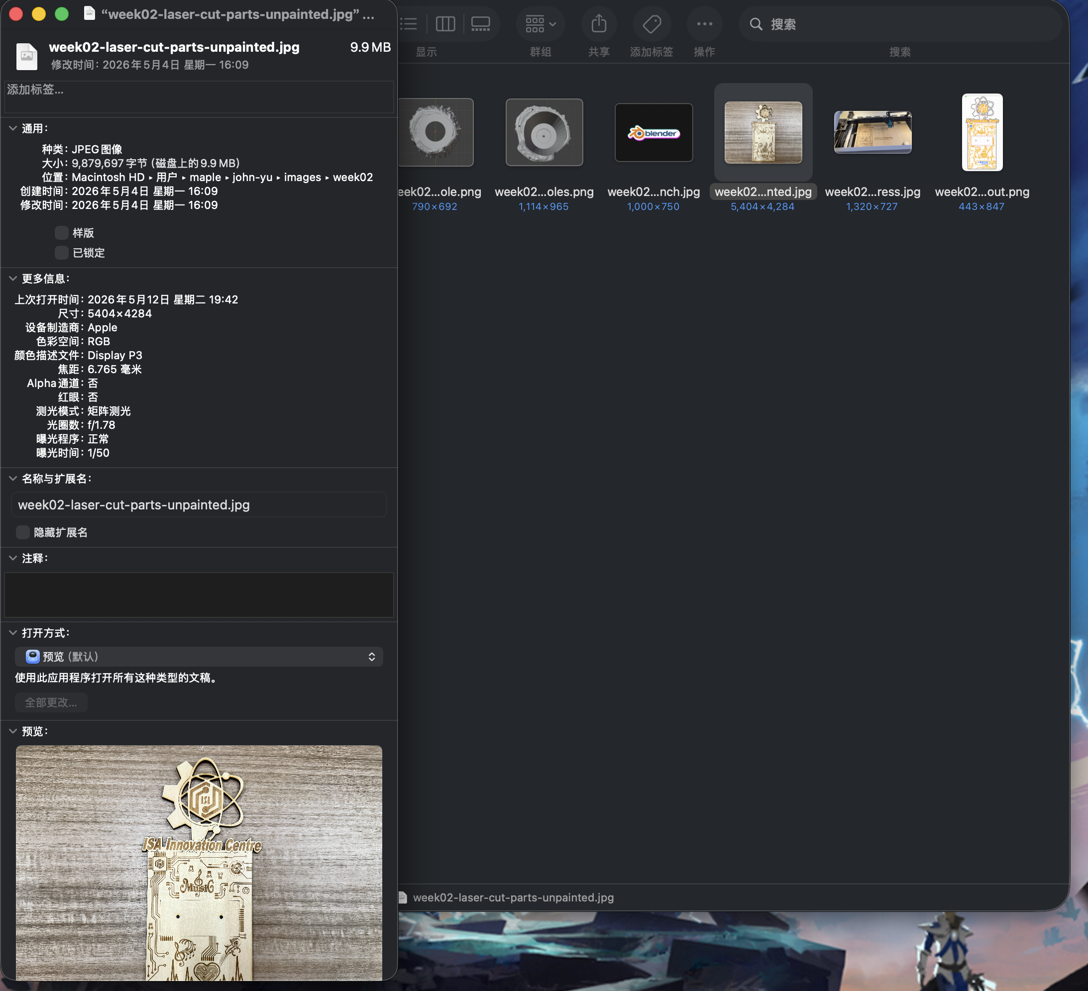
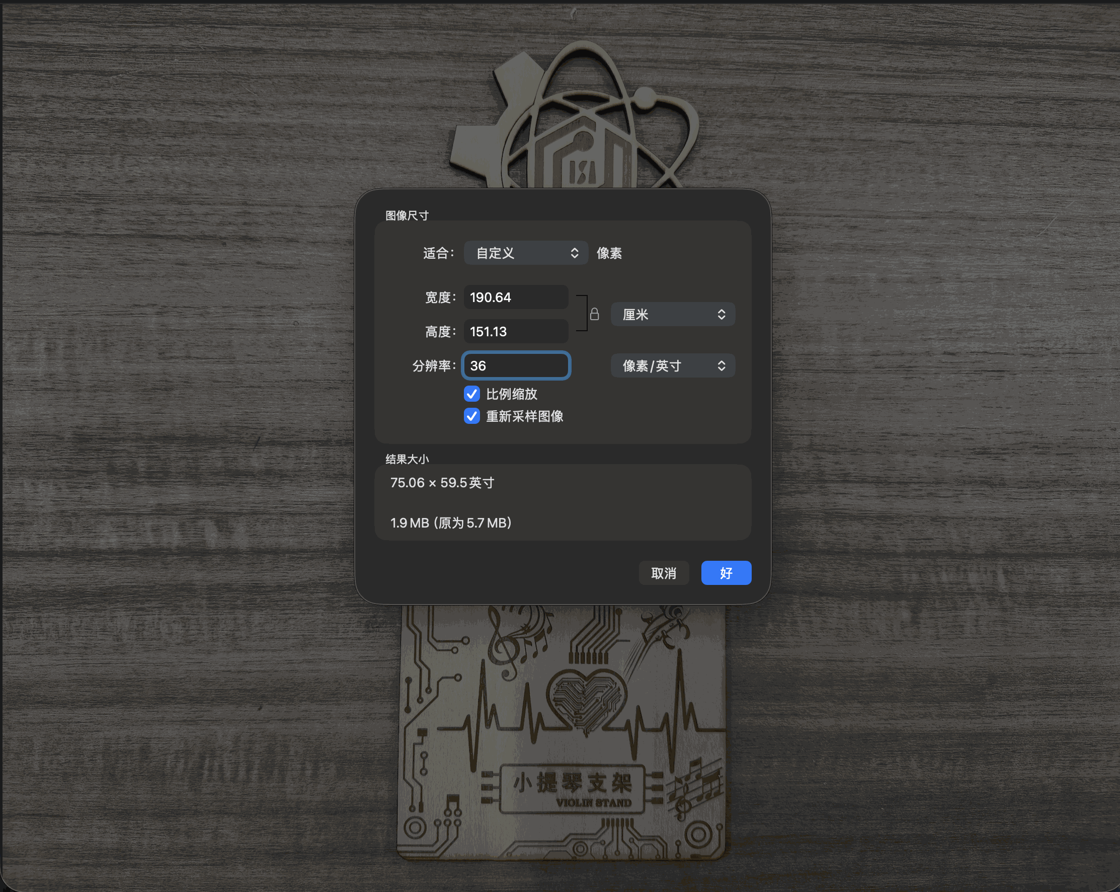
I then used File → Export…, picked JPEG for photographic captures, lowered the quality slider another notch, and saved under a new name so I could compare side by side with the archive copy.
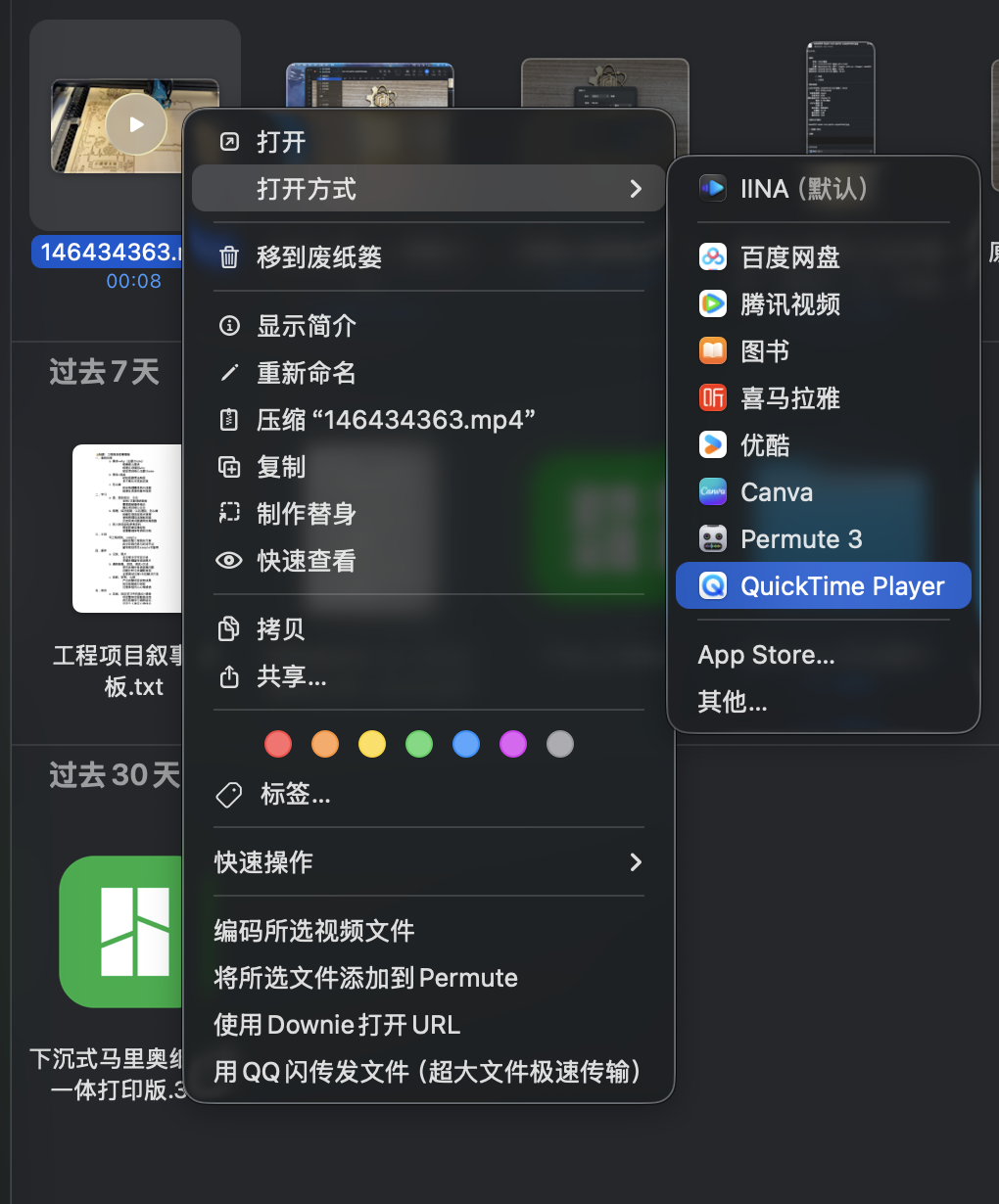
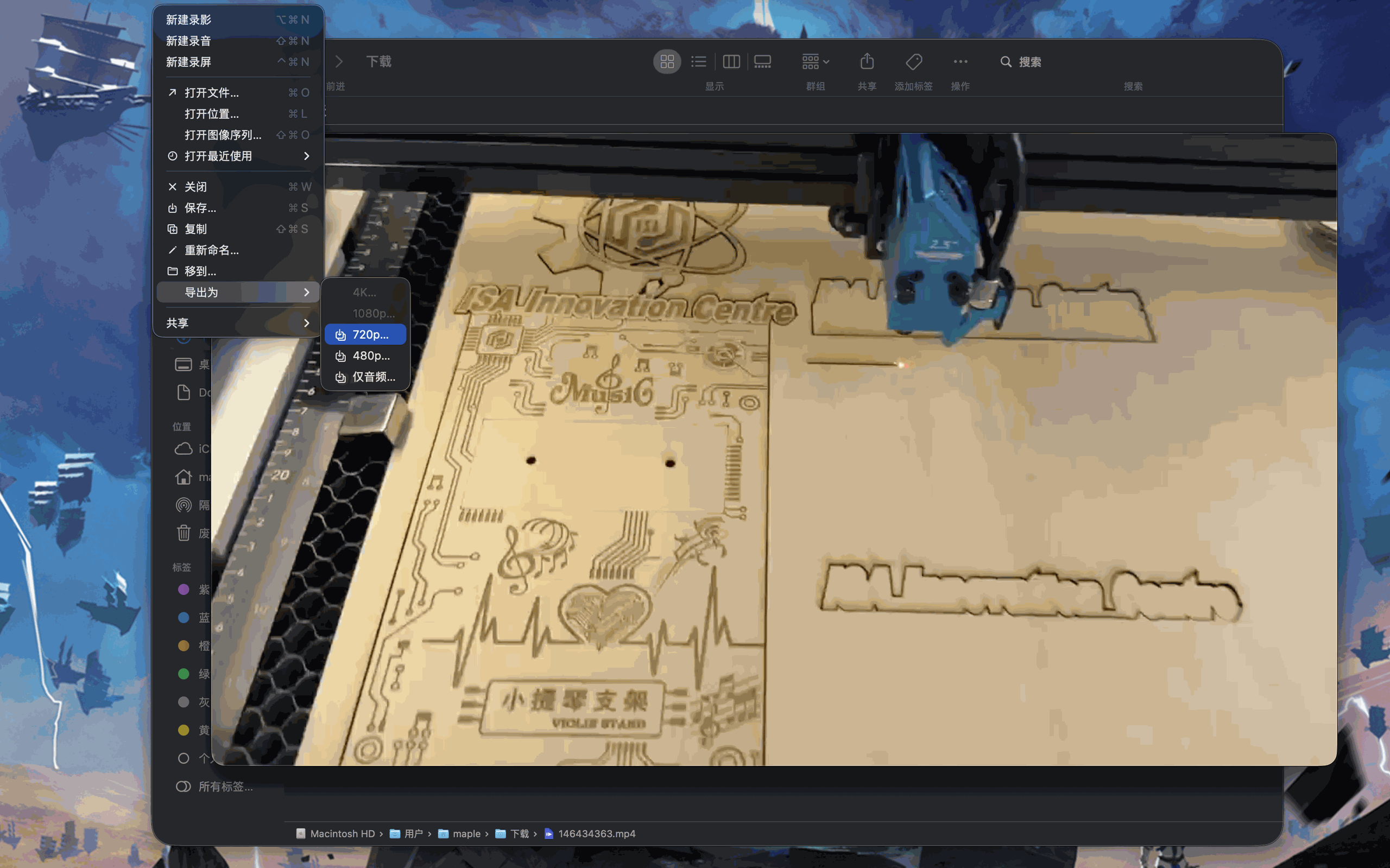
Video: QuickTime Player export
For clips I opened the source in QuickTime Player and exported to a smaller preset (480p or 720p) so fewer pixels ride in each frame compared with the original capture on disk.
Before / after screen recordings
The two files below archive the uncompressed capture and the 480p export I kept for uploads. Both are served as browser-friendly .mp4 files. The scaled export trades frame size for a lighter clip on the page.
week02-video-before-compression.mp4).
week02-video-after-480p.mp4).
Group assignment, media sizing for documentation
Same constraint as elsewhere on the academy site: uploads need manageable stills and short clips without blocking the pipeline. Below is the pass I documented for Lasermaker walkthrough assets; it mirrors the individual section on compressing assets for uploads. For photos I used macOS Preview (Tools → Adjust Size, then File → Export as JPEG) and kept originals under a renamed copy. For video I used QuickTime File → Export As at 480p or 720p and kept both source and scaled exports for comparison.