Week 5: 3D scanning and printing
3D scanning and printing week. I physically printed the Week 2 root-style planter on the omni-wheel base: CAD to a long FDM build on a Bambu Lab H2D, with filament prep, slicing in Bambu Studio, a failed first iteration, and a second run after I fixed how the root and base join in Blender. I also scanned a real object with Luma 3D to document the capture workflow, scanner settings, and final digital result.
Individual assignment: printing the Week 2 planter assembly
What I expected going in
I already had the planter and omni base in CAD from Week 2; this week was about turning that mesh into a single, trustworthy print. I knew the H2D could handle long jobs, but I did not assume the first export would slice cleanly. The organic shell and the flat ring had lived as separate bodies for a long time, and printers punish that. The failure in the first run was frustrating but useful: it forced me back into Blender to fix the union instead of chasing endless slicer tweaks.
Design context (Week 2)
The detailed Blender workflow (import the open-source root mesh, refine it, scale to the rover, taper, add a printable bottom, drive cuts with mask solids, then union and intersect for export) is documented step-by-step with screenshots on Week 2: 3D CAD (Blender). On this page, Designed steps & Blender refinement adds the same eight-step framework in “button path” form plus CAD captures with A/B/C callouts. Below that, the story is mostly slicing, filament, and printing on real hardware.
Why Bambu Lab (H2D)
I print on a Bambu Lab H2D because it matches what this project needs: a large, well-integrated FDM workflow, multi-material readiness, and software that is tuned to the machine. The H2D is a dual-toolhead fused-filament printer with an actively heated build chamber (up to about 65 °C), a heated bed (up to about 120 °C), and high-temperature hotends (up to about 350 °C), so it can cover everyday course plastics (PLA, PETG, TPU, ABS family, PA, PC, and filled variants) without fighting the hardware limits of a small open-frame machine. Official figures list a substantial build volume in dual-nozzle mode (the “total” dual-head envelope is about 350 × 320 × 325 mm, with single-nozzle mode using a slightly different width). The printer ships with Bambu Studio for slicing and remote monitor (live camera, job status, and AMS spool telemetry), which makes multi-hour jobs easier to supervise than ad hoc G-code senders.
Day to day I care more about repeatable results than peak speed: chamber and bed control for warp-prone jobs, filament runout/tangle sensing with the AMS, and software that matches what the machine can actually do. That is why I run Fab Academy prints on this unit. Full specifications are on the vendor page: Bambu Lab H2D — technical specifications.
Filament
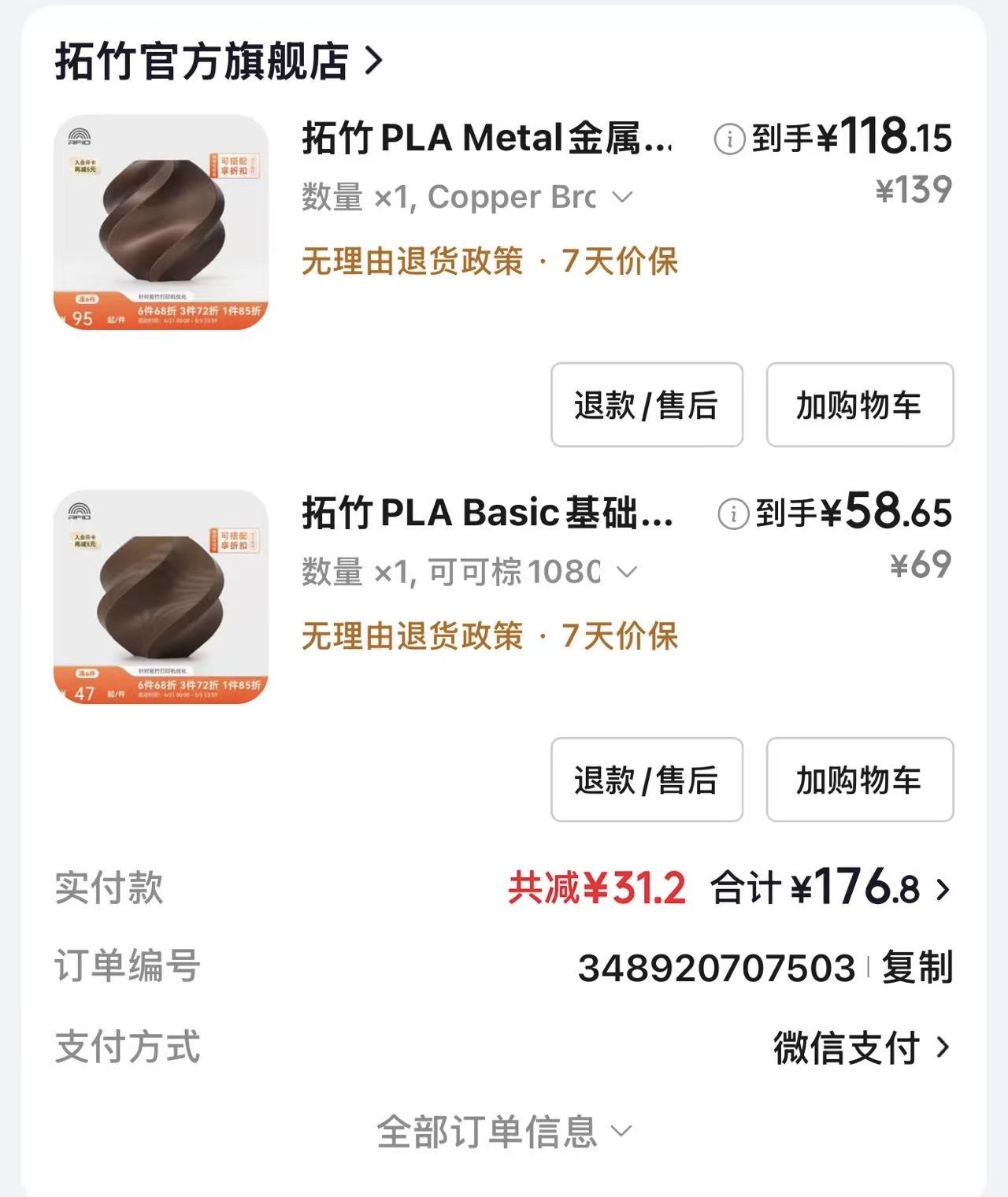
I ordered Bambu Lab PLA from the official store so material labels, color IDs, and spool handling stay consistent with the AMS and the profiles in Bambu Studio. For this build I picked a metal-finish copper-tone PLA plus a cocoa brown basic PLA for contrast. Both are fine for a decorative planter while staying in a straightforward PLA process for a first full-size run.
Preparing and supervising the job
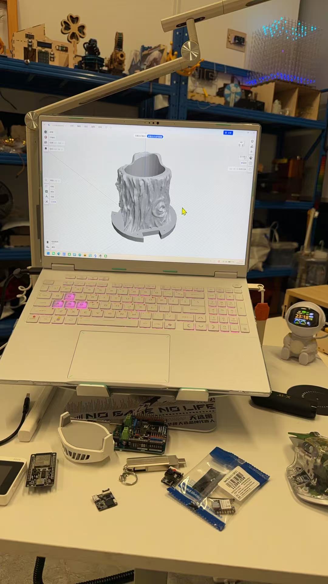
Before starting the machine I checked the model on my laptop in the same environment
where I iterate on electronics for the final project (Figure 2). The print job
name visible in Bambu Studio (shapr3d_export_...) reflects an export filename in
the slicing pipeline; the solid matches the planter-and-base assembly I finalized in Blender on
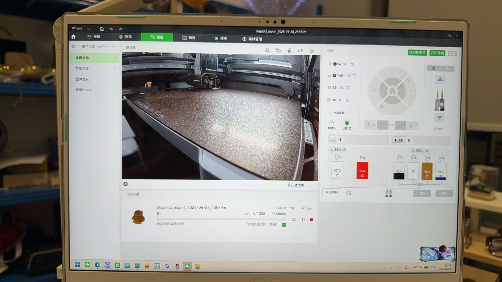
Week 2, in a mesh format the H2D stack accepts. On the
printer side, Bambu Studio’s Device tab lists my machine as
H2D-MAPLE with live chamber camera, heatbed and nozzle status, AMS
slots, and the active spool. For this job the slicer estimated on the order of
1000+ layers and a long overnight run with several hundred grams of
filament, reasonable for a hollow organic shell with fine surface detail.
First print iteration: what went wrong
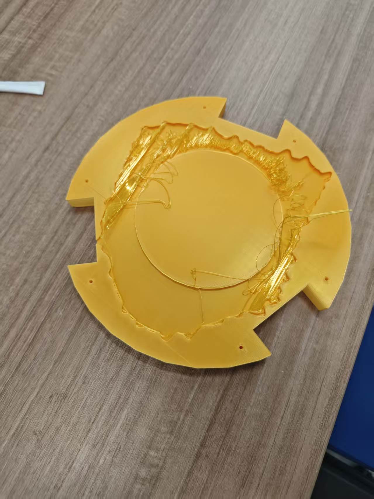
The first full attempt did not stay usable. Before the overhaul, the root mesh and the caster base did not form a single printable solid in the exported file: the organic walls and the flat ring met in slicing as weak islands and long bridges, not as shared perimeters. The failed plate showed heavy stringing and sparse fill at that joint (Figure 5), which points to both slicer limits and CAD that still treated trunk and base as loosely merged surfaces. The path forward was to rework the Blender boolean workflow (especially bottom + union), re-export, then re-slice, rather than only chasing retraction and temperature.
Designed steps & Blender refinement (between print iterations)
This week’s CAD work followed the same eight-step pipeline as
Week 2 (import → detail → scale → taper →
bottom mass → mask helpers → boolean union (trunk + bottom) →
boolean cuts with masks). After the first failed plate I went back to that
checklist and fixed the watertight merge at the root–base interface instead of
nudging slicer settings at random. A one-line-per-step
outline also lives in documents/week05-modeling-process-outline.docx.
Blender operations I used (menus, selection, merge)
Below is the click-and-key path I actually use in Blender 4.x (UI can be English or Chinese; modifier names stay the same). Week 2 narrative covers the eight-step pipeline; here I spell out the menus.
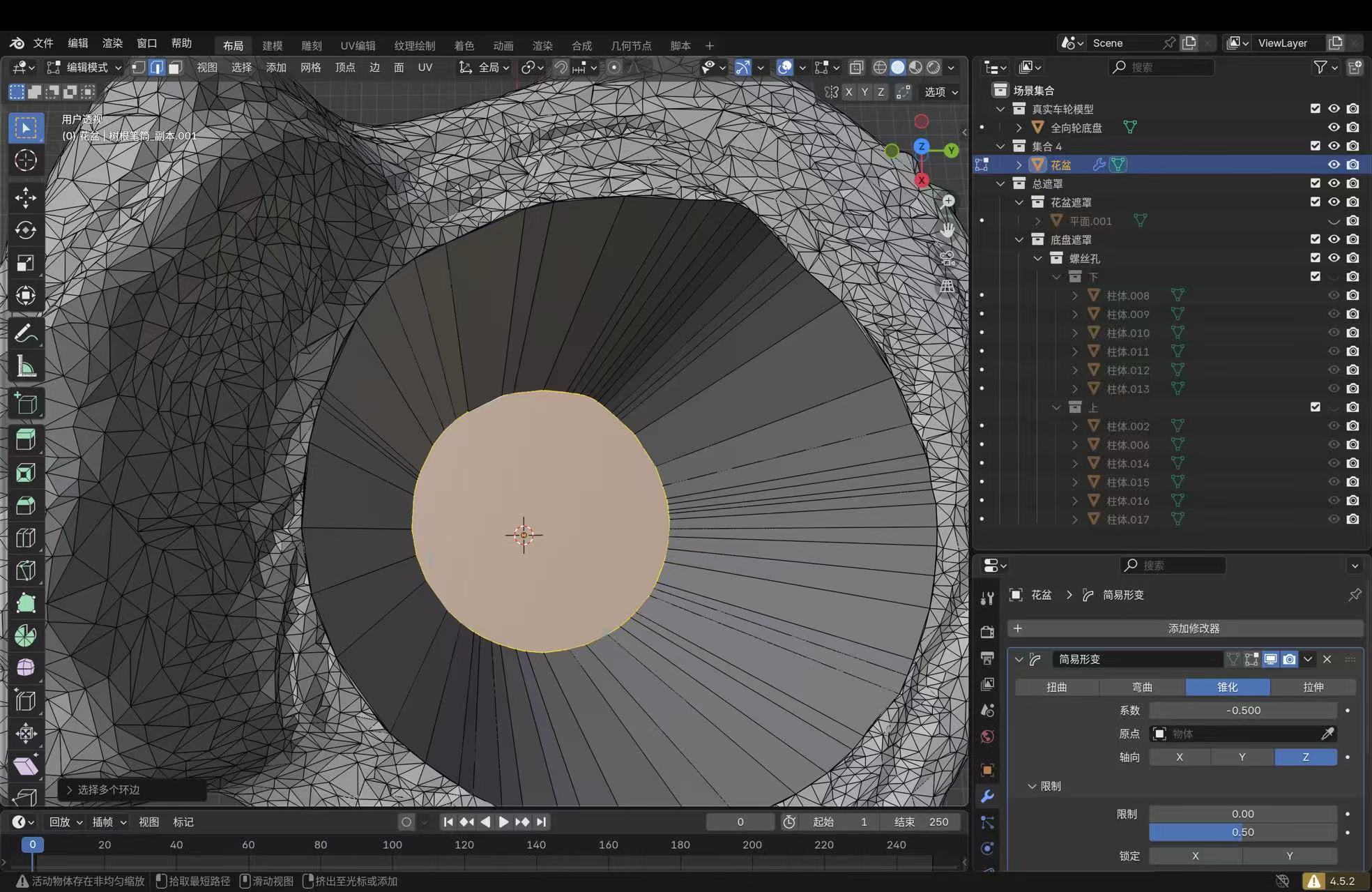
I block out helpers and operands in Object Mode (header menu or Tab), then switch to Edit Mode for face loops, inset/extrude on the opening, or local mesh cleanup. In Edit Mode, 1 / 2 / 3 toggles vertex, edge, and face pick; I used face mode for the planter floor and rim work shown in the CAD captures.
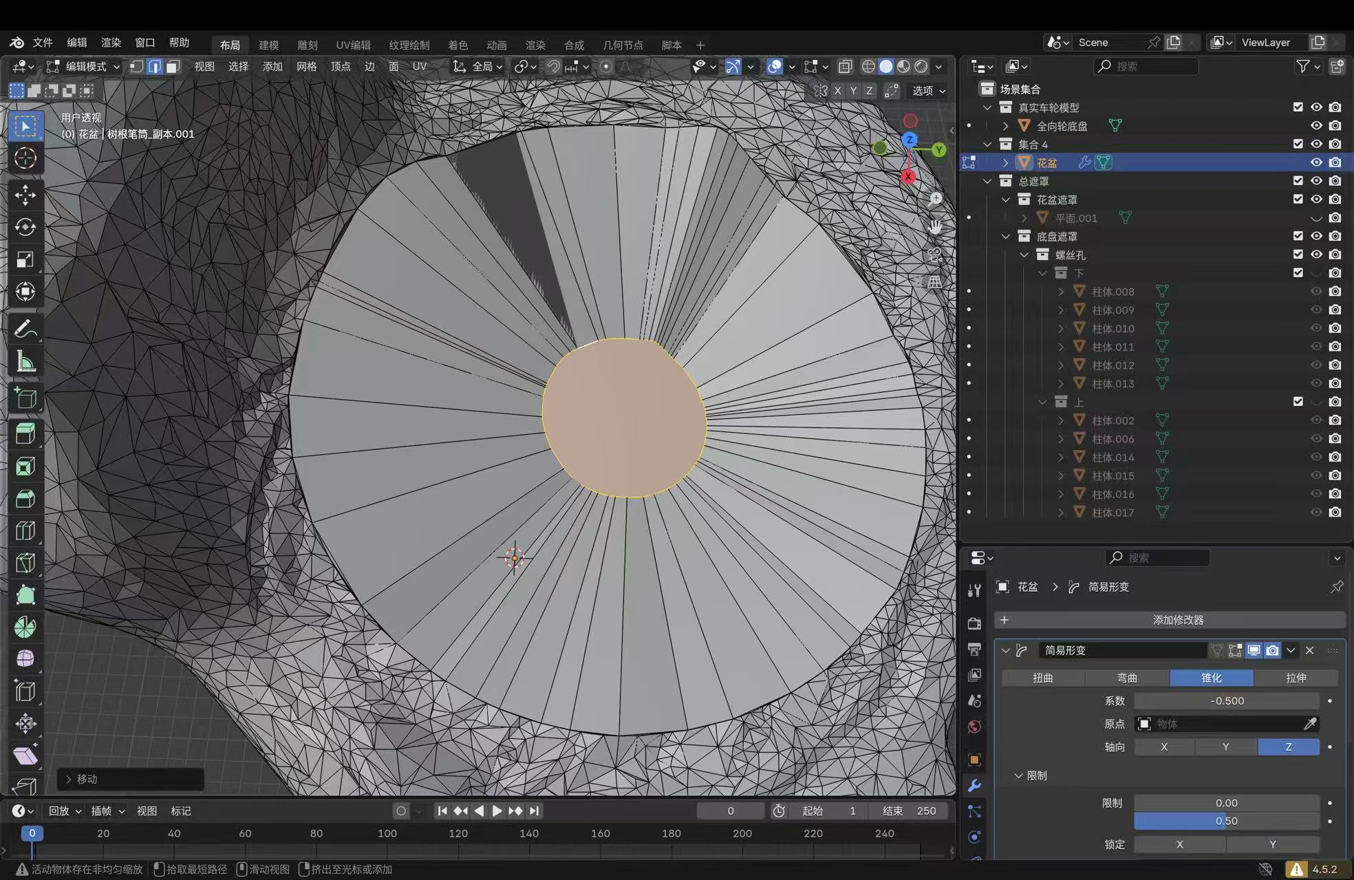
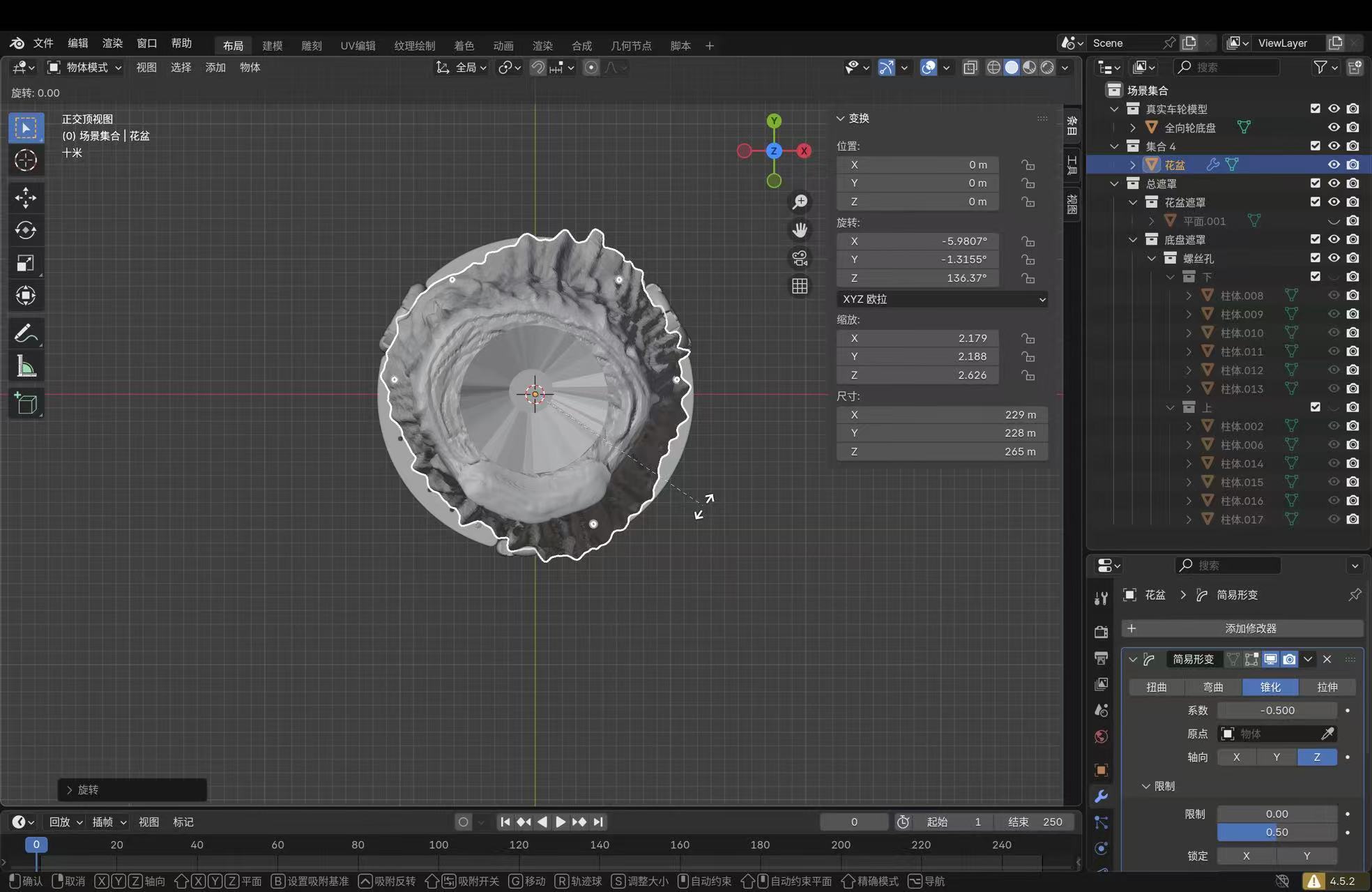
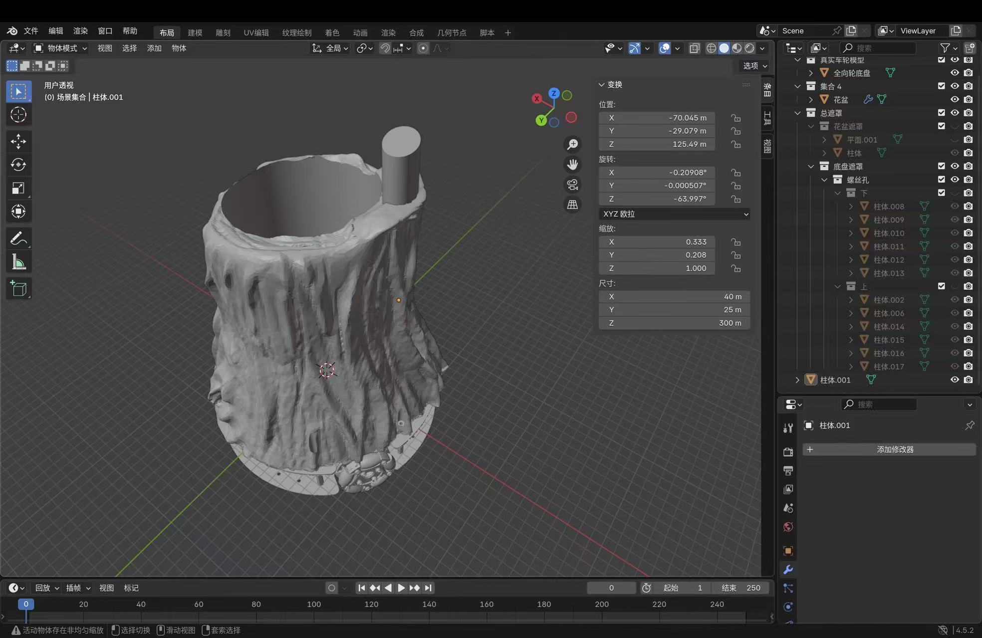
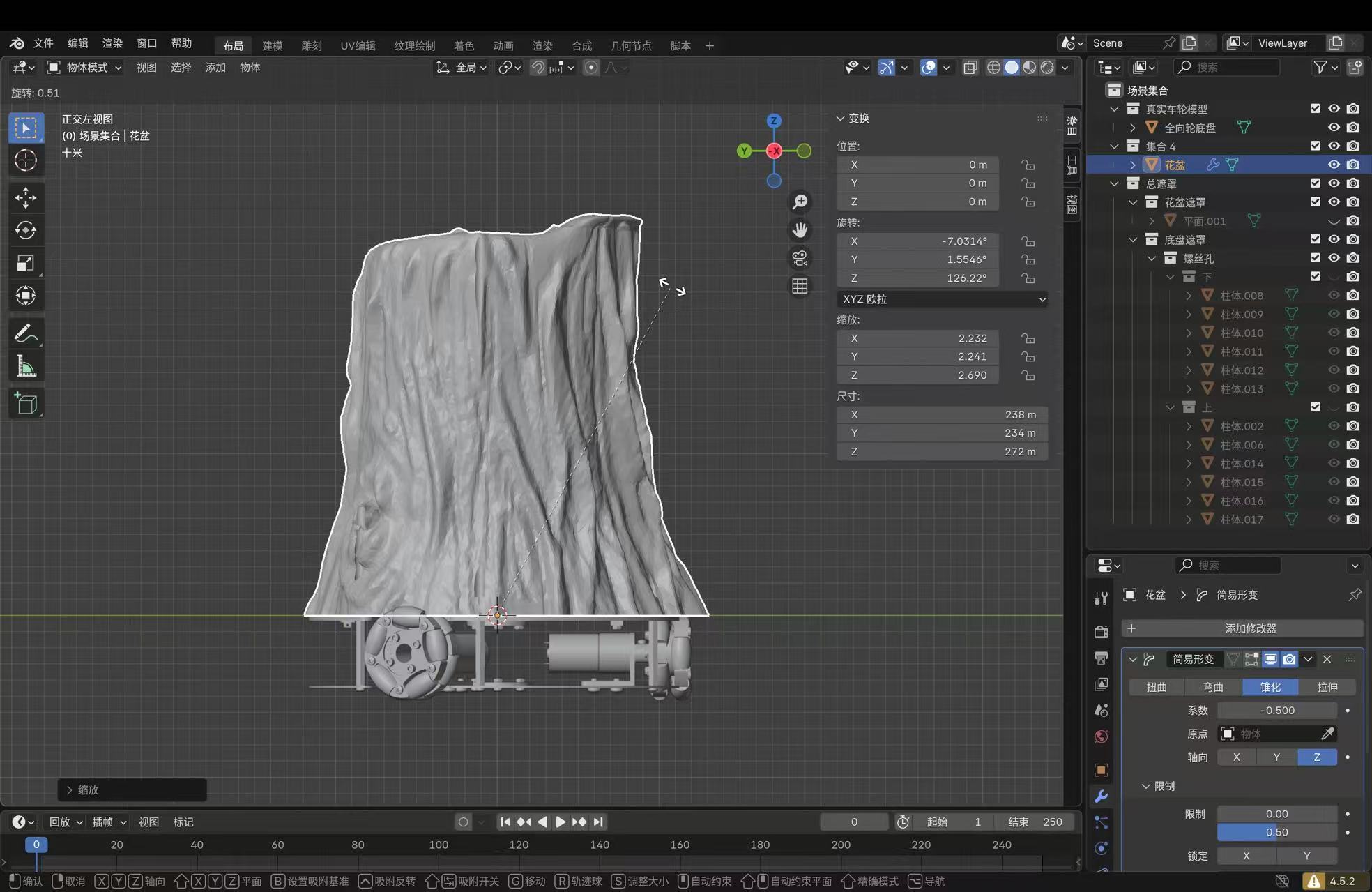
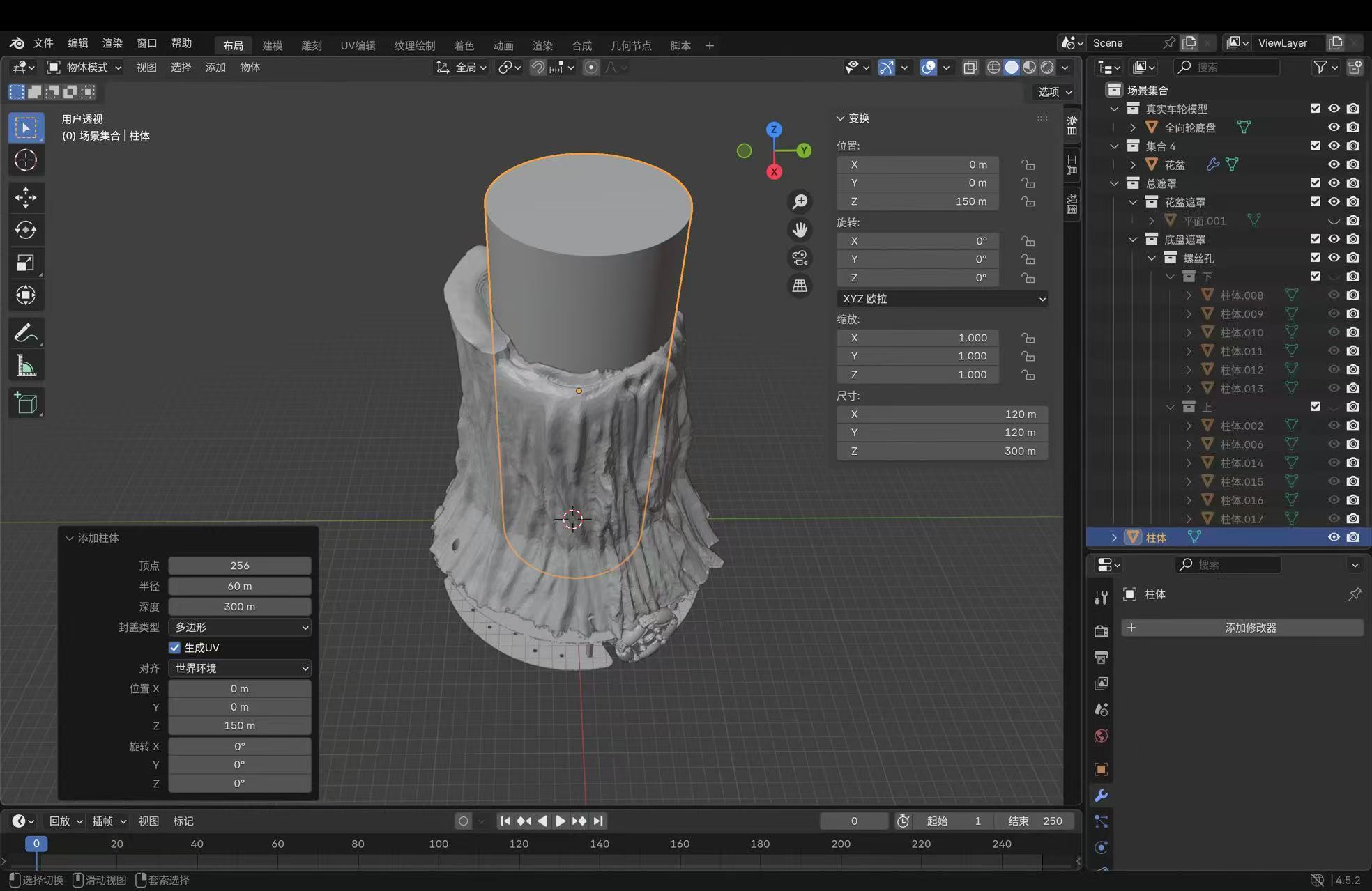
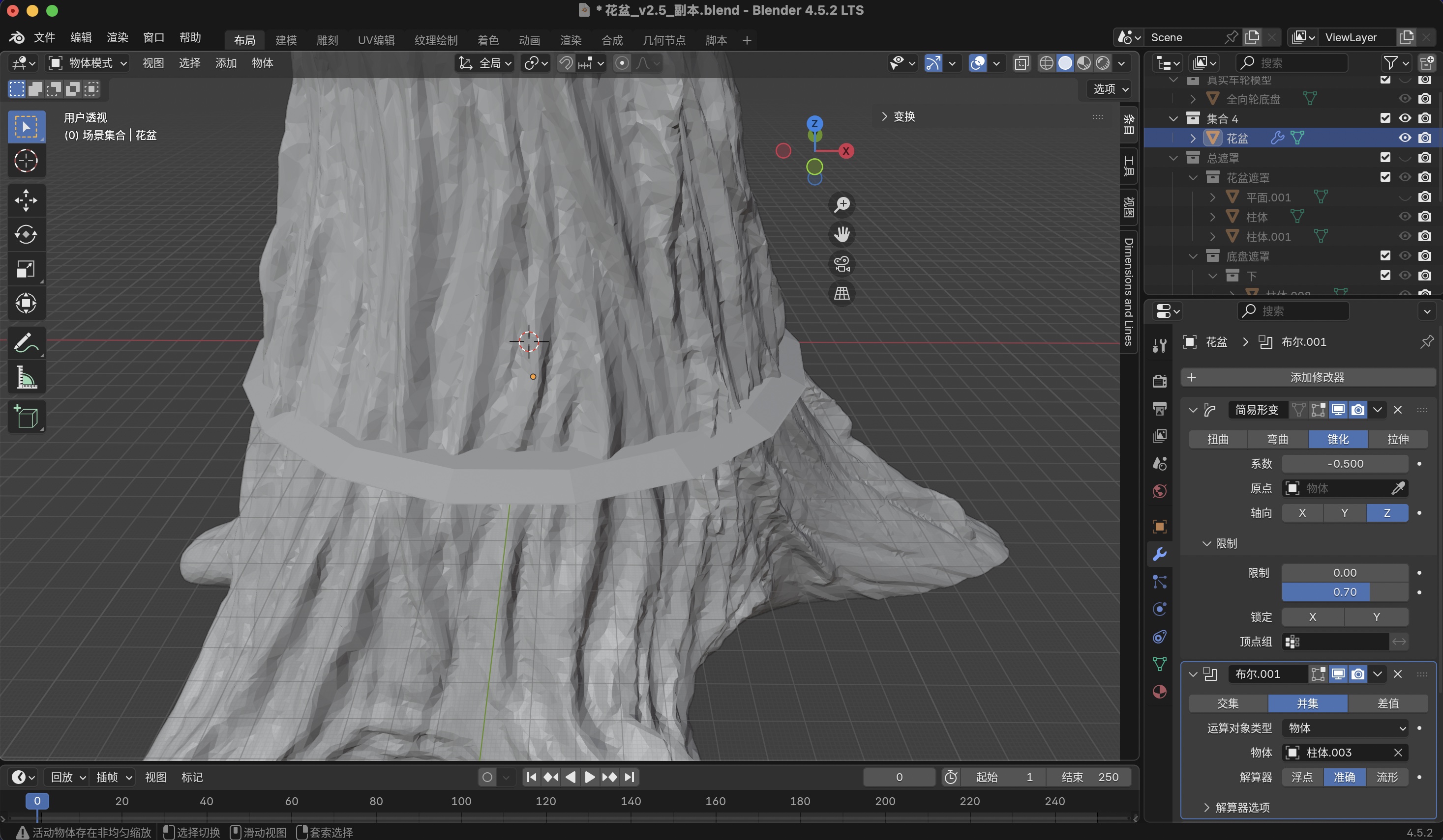
For taper I select the trunk → Properties → Modifier Properties (wrench) → Add Modifier → Deform → Simple Deform, method Taper, axis Z, tune factor and Limits so only the lower portion narrows. I leave the modifier live until booleans stabilize, then Apply when I need a frozen stack for export. Bottom and routing columns come from Add → Mesh → Cylinder (or Cube) in Object Mode, moved and scaled with G / S and axis keys so they overlap the trunk on purpose.
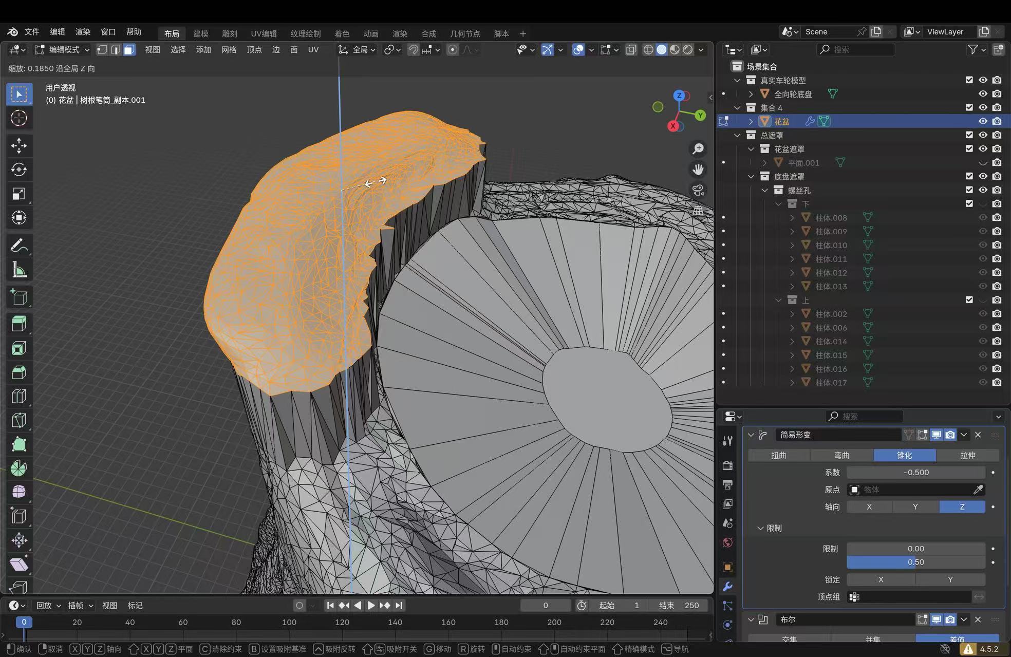
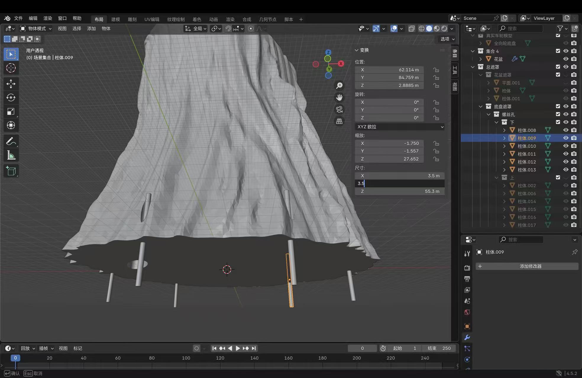
Boolean merge is what “合并” means here: on the trunk object, add Boolean,
operation Union, pick the bottom/ring operand with the Object eyedropper (often
a cylinder such as 柱体.003), solver Exact on recent builds. When
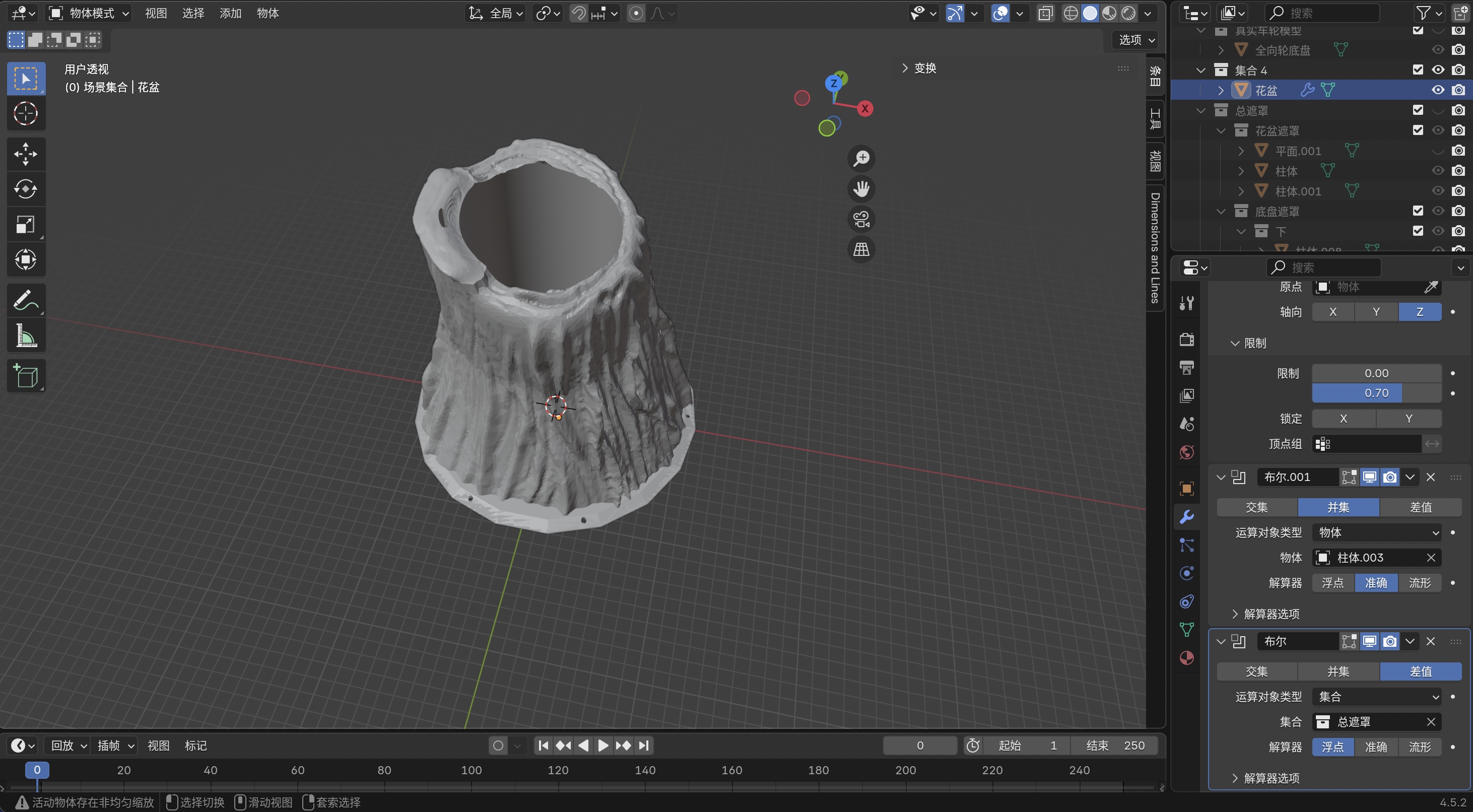
the viewport looks right, apply from the modifier menu. For holes and pockets I use
Difference or Intersect with mask solids kept in a
总遮罩 / 螺丝孔 collection. Ctrl+J joins objects
into one datablock but does not guarantee a printable solid; at the trunk–base junction I rely on
Boolean Union, not Join alone. If the status bar warns about non-uniform scale, I select the
object → Ctrl+A → Scale before heavy booleans. Viewport
Annotate (toolbar pencil) is for temporary markup; site captions below replace
grease-pencil strokes so text stays selectable.
CAD refinement: screenshots with callouts
The following grabs are from the same .blend I sliced after fixing the union. Bullet labels (A, B, …) point at the UI regions that matter for reproducing each step (your interface language may show Chinese strings; modifiers line up 1:1).
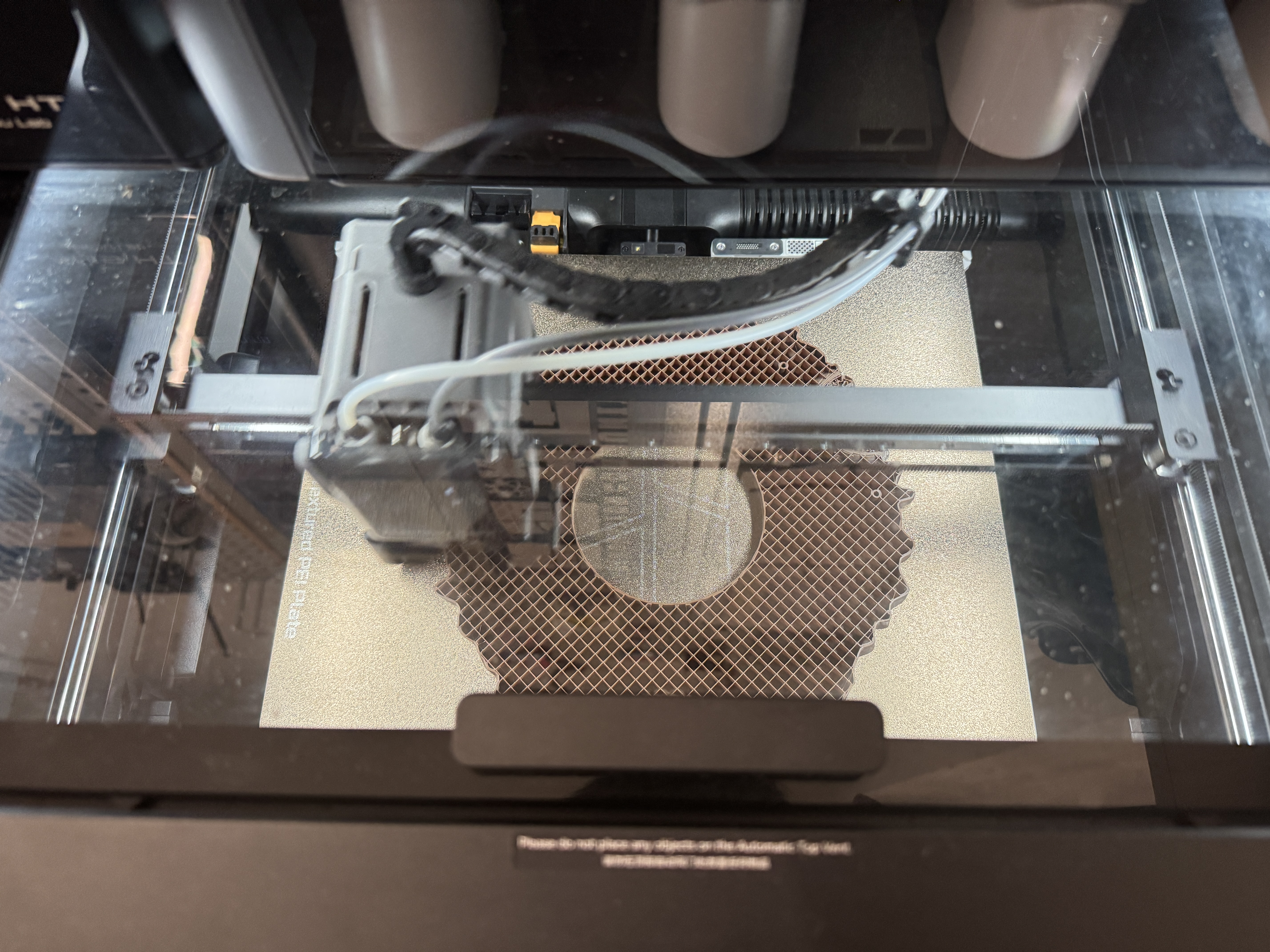
Second print: corrected build
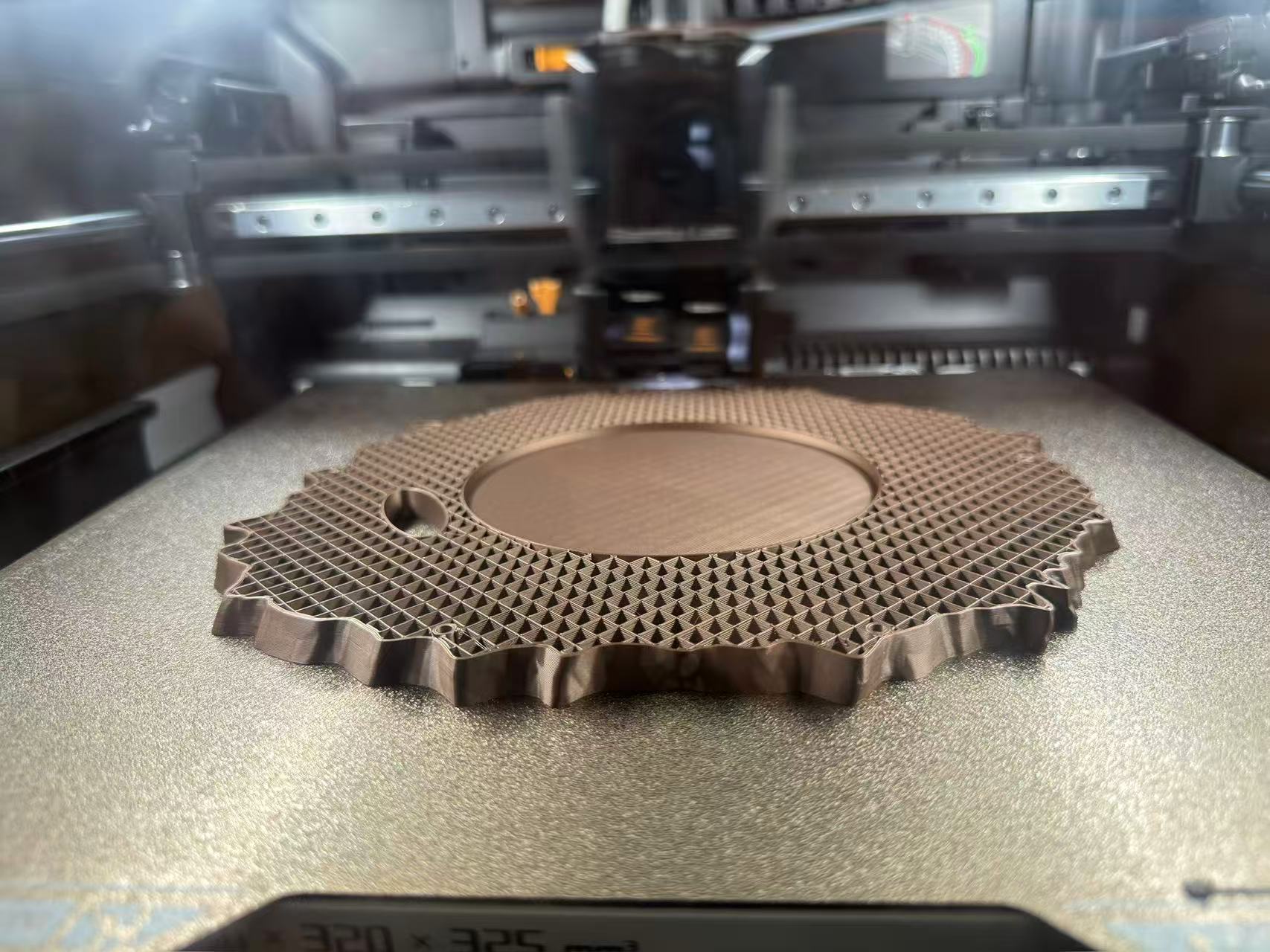
After the union/intersection pass gave a single solid interface, I re-exported, re-sliced in Bambu Studio, and ran a second full-height job on the same H2D. Figure 16 looks straight down through the lid during that run: the wheel ring and outer rim adhere cleanly to the textured PEI sheet, rectilinear infill reads inside the plate, and extrusion at the old trouble zone is continuous instead of the first plate’s tangled bridges. Same filament profile as before. The improvement is mostly geometry, not exotic slicer tweaks.
Print process: progression on the bed
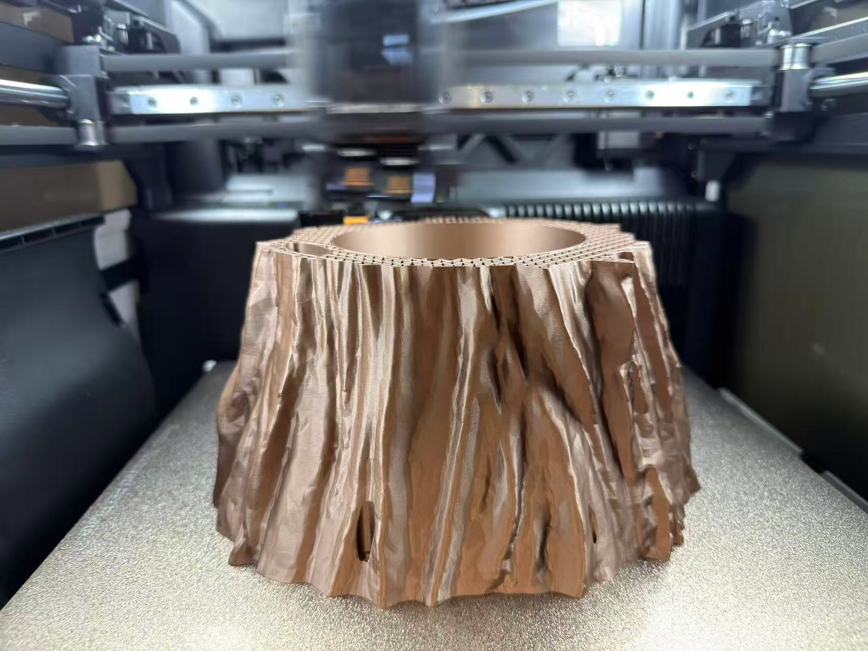
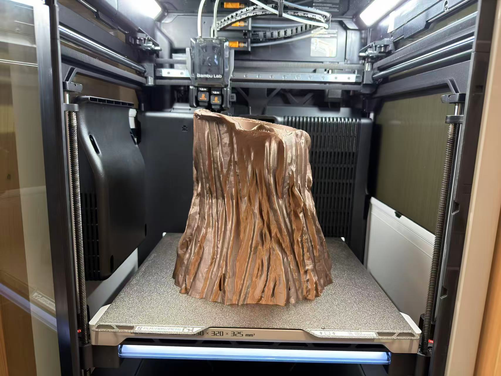
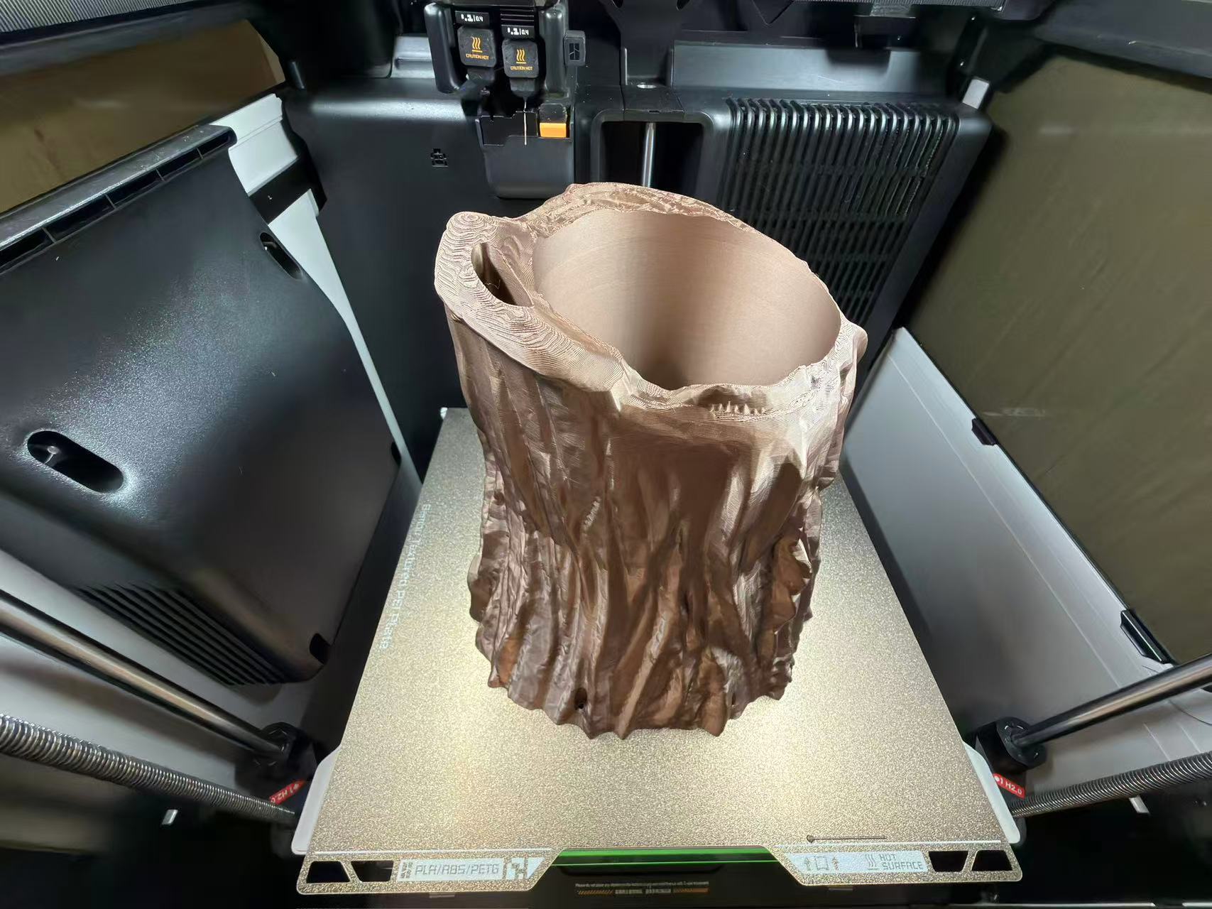
Four in situ photos from the corrected run show FDM stacking on the textured PEI plate: skirt/brim and perimeters, then thickening walls and infill, then the root shell rising above the wheel platform with a printable junction between trunk and base. That is what the boolean-heavy CAD workflow was aiming for.
Finished print: short clip
After the job finished, I recorded a quick look at the part off the machine: the copper-tone shell sitting on the omni-wheel base so the junction from the CAD iteration is visible in hand rather than only through the chamber window.
3D scanning: Luma 3D book capture
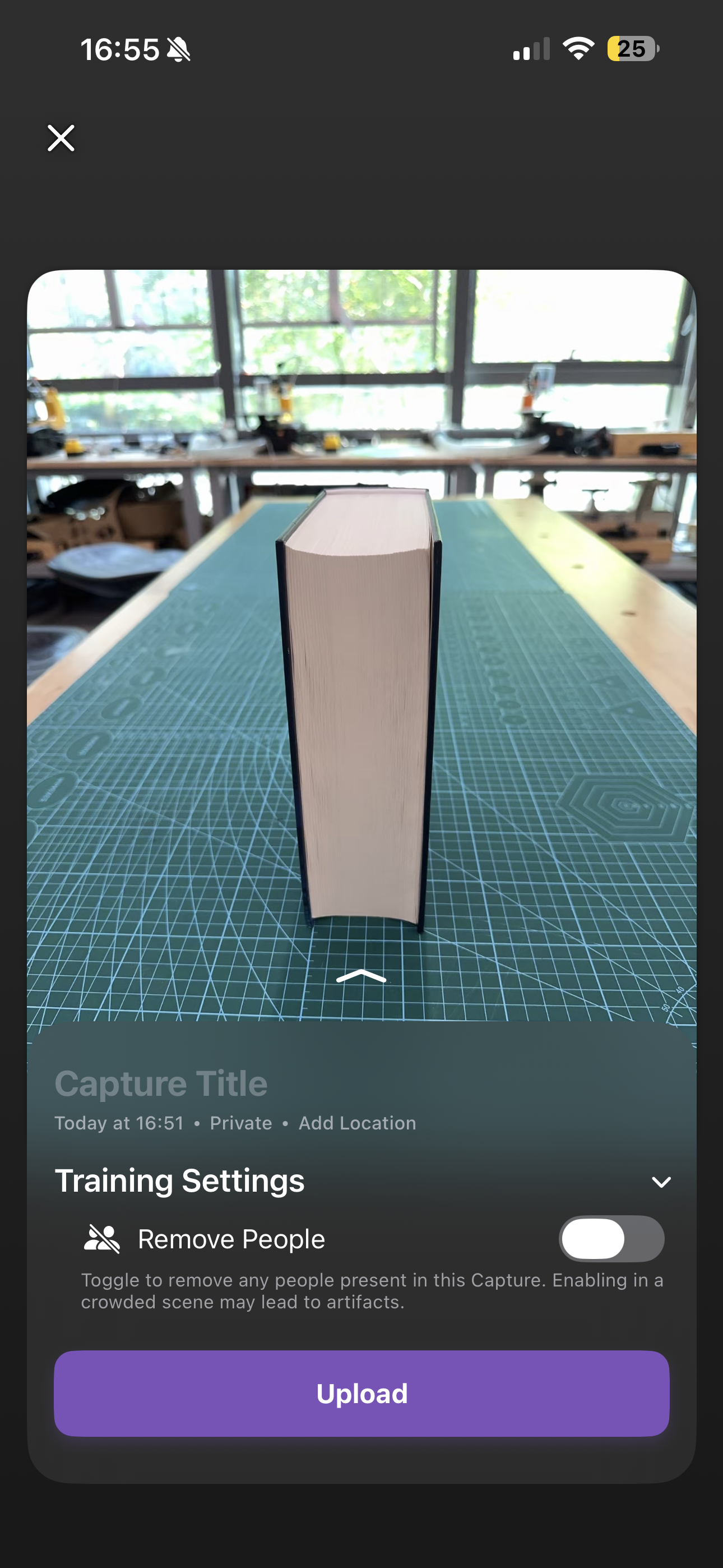
The part missing from my first submission was the 3D scanning process. I used Luma 3D on my phone because it gives a guided object-capture workflow: instead of only taking one photo, I walk around the object and let the app reconstruct a textured 3D scene from many views. For this scan I chose a book because its shape is simple enough to check alignment, but it still has readable front-cover texture and a clear top, side, and back surface.
My capture setup was: object placed upright on the lab cutting mat, bright ambient light from
the window, Object capture mode in Luma 3D, title set to
book, privacy left as Private, location not added, and
Remove People left off because no person was inside the close capture area.
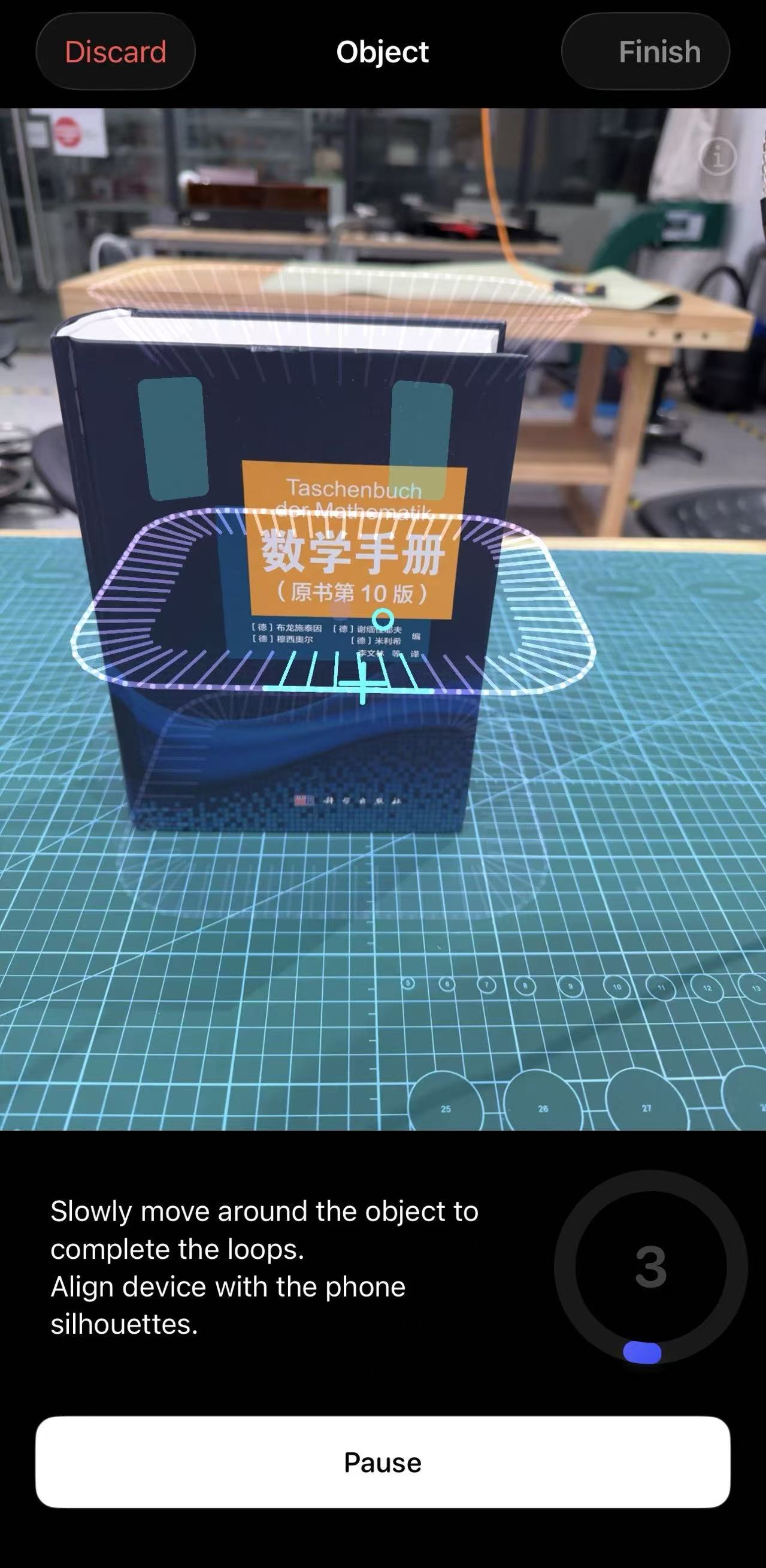
The important scanning parameter was the path: I followed the app instruction and moved slowly
around the book in three height loops (low, middle, high), keeping the phone
aimed at the book so the silhouettes on screen stayed aligned.


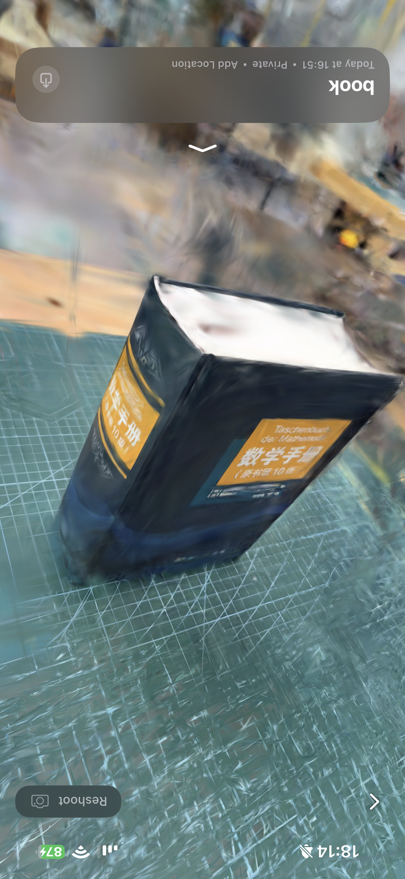
The result taught me the basic limitation of phone-based scanning: large flat faces are easy to recognize, but reflective plastic edges, bright paper, and background clutter can produce soft or warped geometry. If I repeat this scan, I would add a small turntable or a less busy background, keep more distance consistency, and take an extra slow pass around the top edge so the paper block reconstructs more cleanly.
Summary
Week 5 finishes what I started in Week 2: the root planter on the rover base is now a real Bambu Lab H2D build. I documented filament sourcing, slicer and on-machine UI, the failed first plate, and the second print after I rebuilt the mesh with the same eight-step CAD sequence (tooling detail and annotated captures in Figures 6–15 here). Lesson I am keeping: even scan-ready or sculpt-heavy meshes need solid printable joints. I also documented the Luma 3D scan as a separate workflow: setup, capture settings, three-loop scanning path, cloud processing, and final reconstructed result. A mesh that looks fine in the viewport can still fail on the bed if trunk and base never fused into one watertight solid; a scan that looks easy in the app can also lose detail if the object edges, lighting, and background are not controlled.
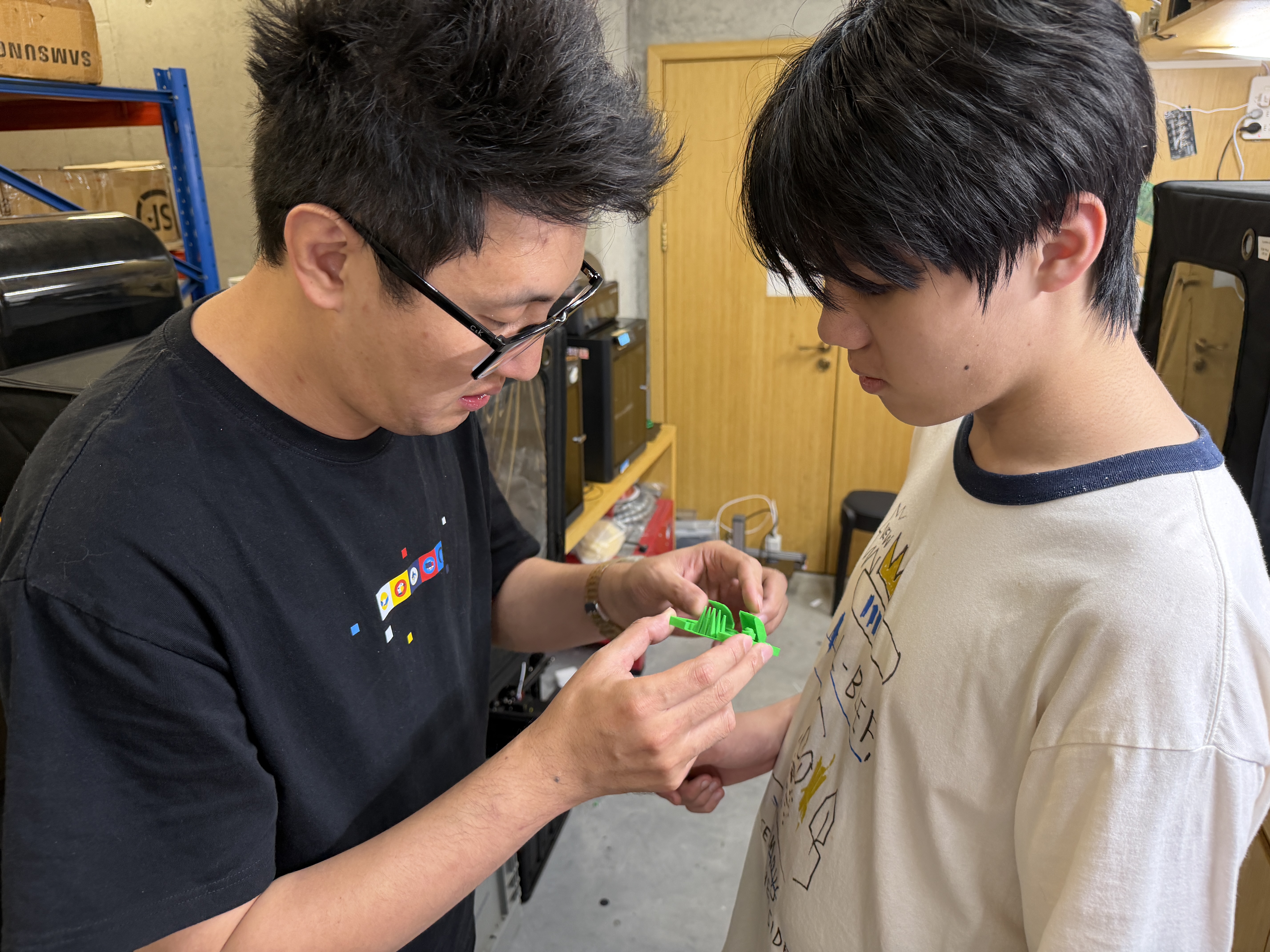
Group assignment
Guangzhou (Chaihuo) group documentation: design-rules testing for the lab’s 3D printer (FDM).
Abstract
The group runs a deliberate design-rules campaign on the specific printer(s) available at the site: overhangs and bridging, clearances and gaps, wall thickness, and angles (supported versus marginal versus unsupported surfaces), aligned with Fab Academy “Testing Design Rules” guidance. The outcome is a short, evidence-backed design-rules sheet with slicer settings, nozzle/layer height, filament, and pass/fail or measured limits, so future work on that machine starts from measured behaviour instead of guesses.
1. Printer, filament, and slicer baseline
We recorded the machine model, nozzle, bed, filament type/brand, and the baseline slicer profile used for the test coupons.
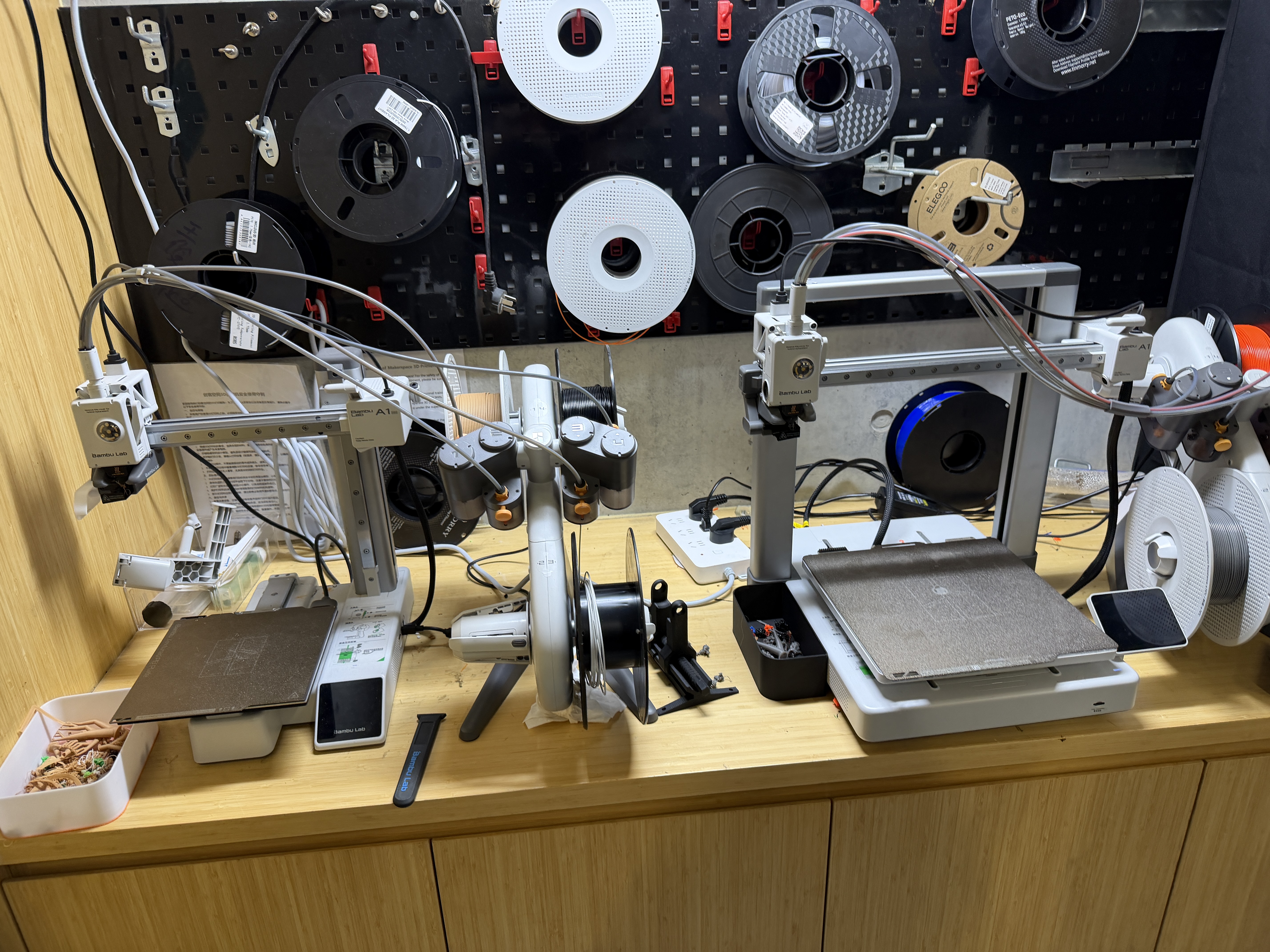
Several FDM machine form factors were visible in the lab; the documented tests refer to the specific printer and slicer profile your group selected.

2. Test geometry and procedure
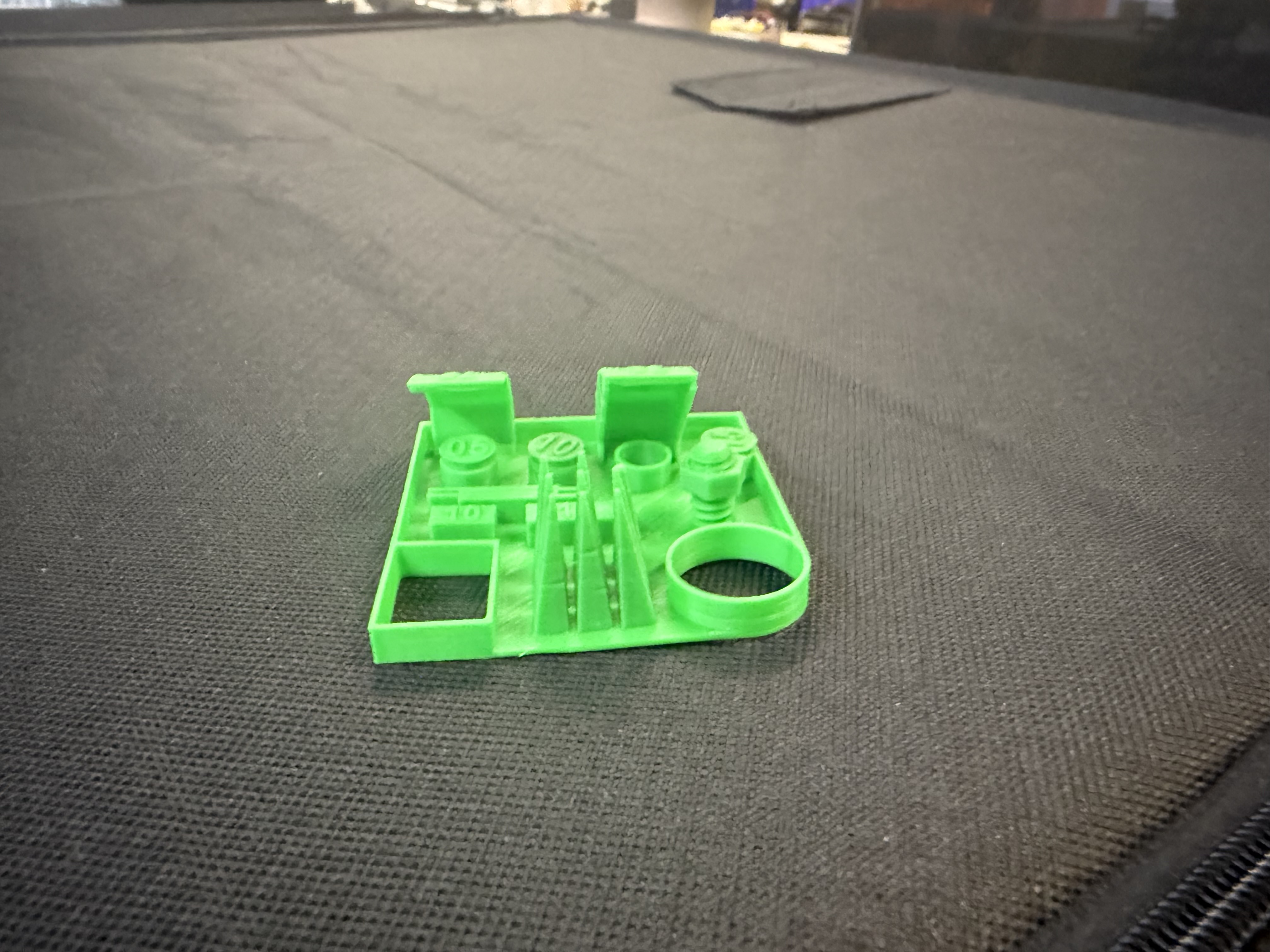
The test prints covered the normal FDM questions: overhang angle, bridge span, clearance, wall thickness, and small features. Each coupon gave us one number or pass/fail observation to carry into later design work.
3. Results
We photographed the coupons before removing them from the bed, then compared visible failures with the nominal dimensions in the slicer. The photos below are the evidence I kept for that table.
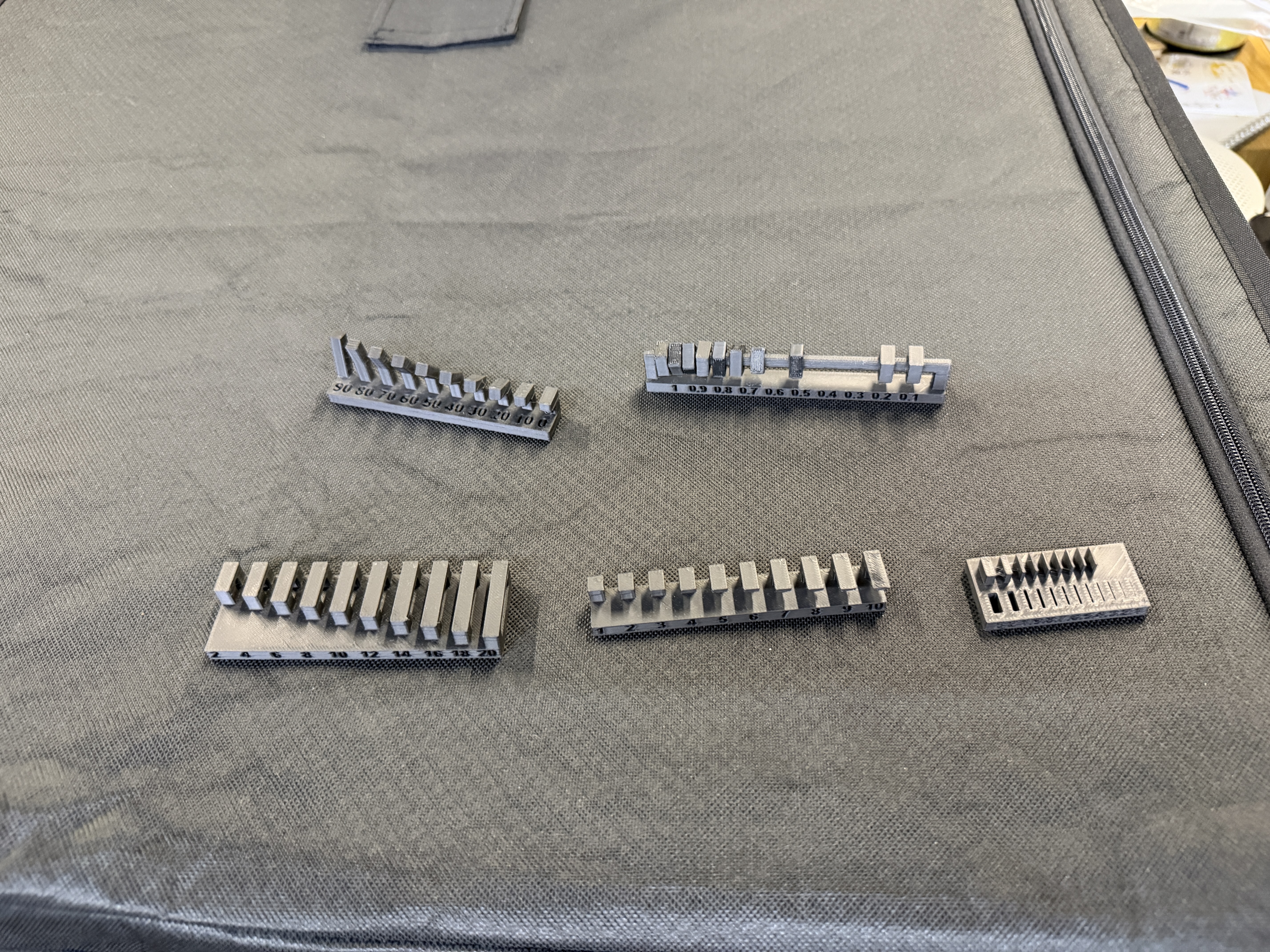
A source capture was also saved as
3d-print-test-parts.heic; the JPEG3d-print-test-parts.jpgis used here for broad browser compatibility.
4. Recommended design rules
The useful output is a short set of limits: minimum wall that survives, maximum unsupported angle before the underside gets rough, and the minimum gap that still moves after printing. I use those numbers before committing final-project parts to a long print.