Week 16 - System integration (Forest Fairy)
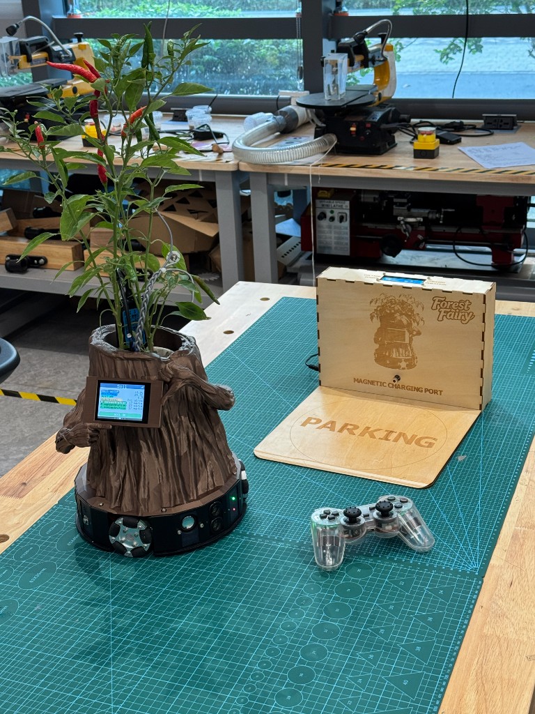
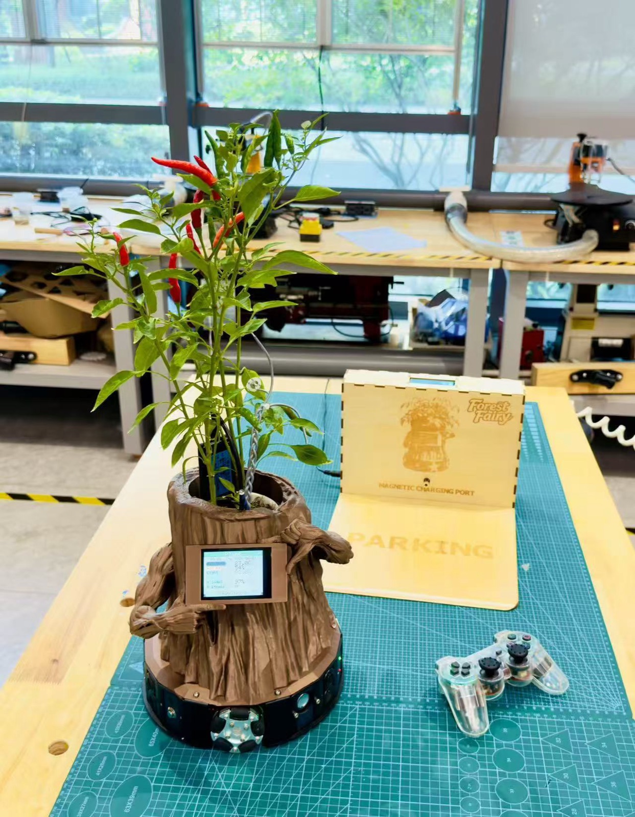
This week I stopped treating Forest Fairy as separate bench tests and started putting it into one body. I checked the Fab Academy 2026 System Integration notes before I wrote the page, because the requirement is broader than "the code runs." I had to show a plan, sketch how the parts fit, put the electronics into the object, make the prototype read as finished, and connect this work back to the final project. For my build, that meant the plant and user inputs had to enter the boards, the screen / speaker / motors had to answer back, and the wiring had to live inside the mobile plant companion instead of spreading across the desk.
Individual assignment
I began this week by reading the Fab Academy System Integration checklist and comparing it with the mess on my desk. The page asks for planning, CAD or sketches, packaging, a finished-looking prototype, and a link from the final project page. My work followed that order in practice: I first proved the cloud voice chain on the bench, then placed the boards, routed wires, fixed power problems, closed the body, and tested the same functions again after they were no longer easy to reach.
Official checklist I used
| Fab Academy question | Where I answer it on this page |
|---|---|
| Did I make a plan for system integration? | Cloud voice system map, final signal map, and the packaging sketch below. |
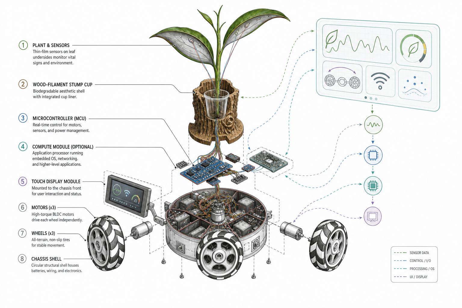
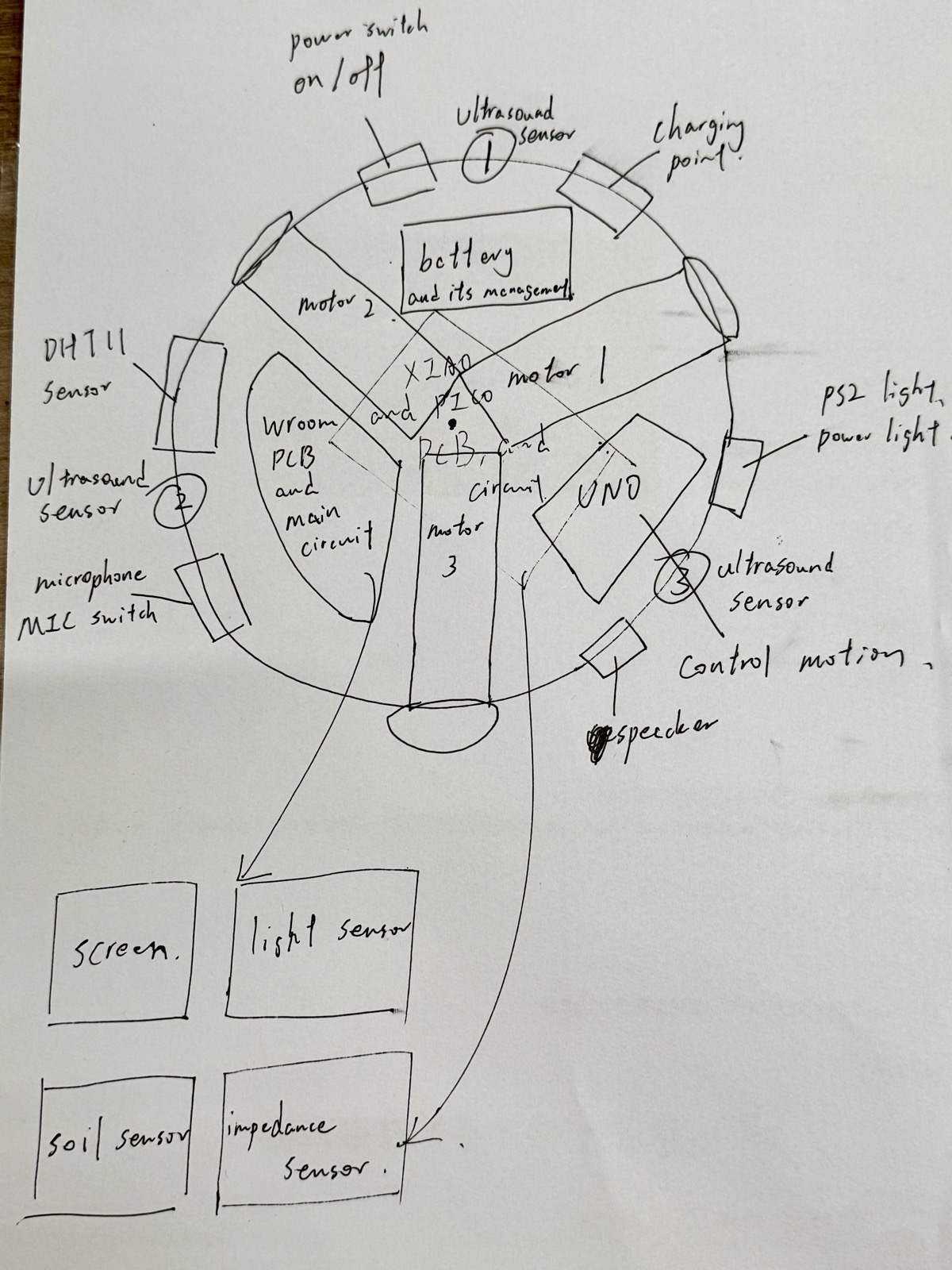
| Did I document the plan with CAD and / or sketches? | The hand sketch and exploded visual map show where the plant, screen, boards, motors, battery, and sensors go. |
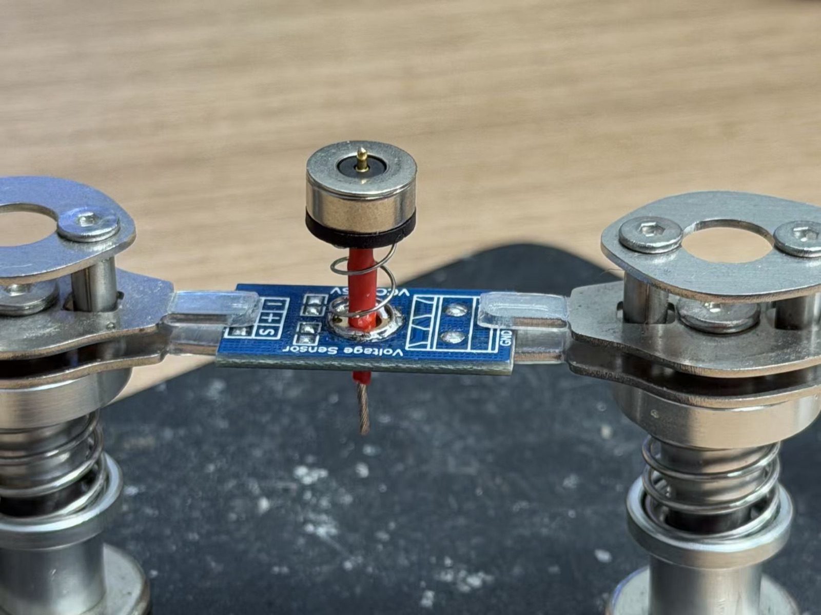
| Did I implement packaging? | The boards, battery, display, sensor wires, and charging contacts are mounted or tied into the body. |
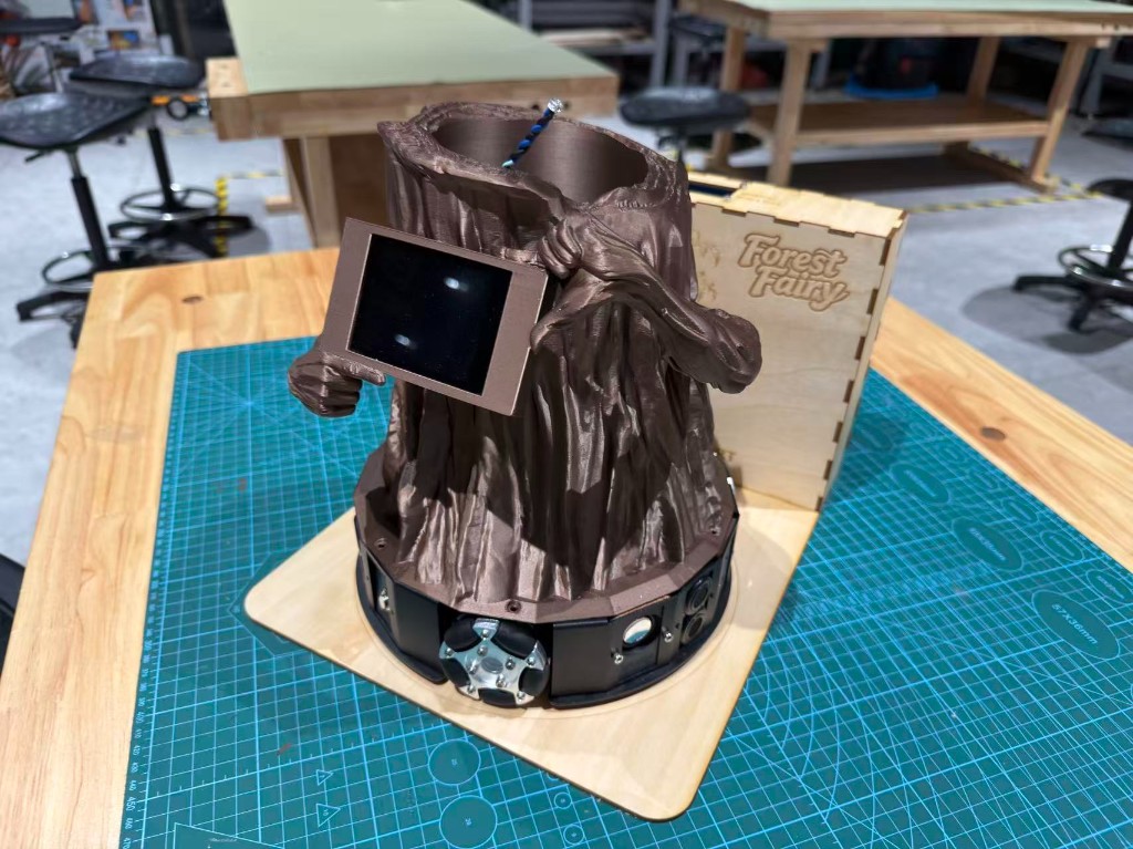
| Does it look like a finished product? | The hero photo, final photos, and demo video show the prototype as one object, not only as a breadboard test. |
| Did I link this from my final project page? | The final project page links back to this Week 16 documentation. |
1) Cloud voice summary, full write-up on Week 15 §11
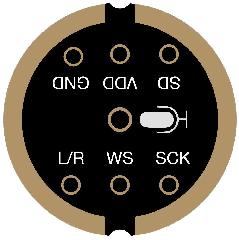
Before I packaged the body, I needed open Mandarin speech working on the bench. The path was mic to Alibaba Bailian ASR / LLM / TTS, then back to the ST7789 and speaker. I rejected the full XiaoZhi firmware because it did not fit my board and UI plan, but I kept its mic and speaker hardware. Console setup, hardware photos, and source files are documented on Week 15 §11.
  ┌─────────────┐   16 kHz PCM / push-to-talk   ┌─────────────────────────────┐
  │ Microphone  │ ────────────────────────────▶ │ Alibaba Bailian cloud app   │
  │ input       │                               │ ASR → LLM → TTS             │
  └─────────────┘                               └──────────────┬──────────────┘
                                                               │ text + audio
                                                               ▼
                                             ┌────────────────────────────────┐
                                             │ ESP32 program + screen/audio   │
                                             │ ST7789 chat page + I2S speaker │
                                             └────────────────────────────────┘
2) Putting the modules into one object
After the cloud voice and display path worked on the bench, I moved the same work into a packaged object. I made the system map first so I could stop guessing where each board belonged. Then I placed the boards, routed power and data, mounted the I/O devices, closed the body, and tested the full function again with the wires hidden inside.
Step 1: draw the whole system map
I started by listing what the final project needed to sense and express. The input side includes voice, light, temperature / humidity, soil and plant-side signals. The output side includes the screen, voice / speaker feedback, motion, LEDs, and the charging dock. Once I wrote this down, it became easier to decide which board should own each task instead of letting every board do a little bit of everything.
  Plant + user inputs
  ├─ voice microphone / cloud speech
  ├─ light, DHT11, soil and impedance signals
  └─ buttons / touch where needed
            │
            ▼
  ESP32-S3 / WROOM program
  ├─ read sensors and voice events
  ├─ call Bailian ASR / LLM / TTS when online
  ├─ keep local UI state
  └─ send output commands
            │
            ▼
  Outputs
  ├─ ST7789 display pages
  ├─ speaker / TTS feedback
  ├─ motor chassis movement
  └─ LEDs / charging dock indicators
Step 2: decide where every part lives
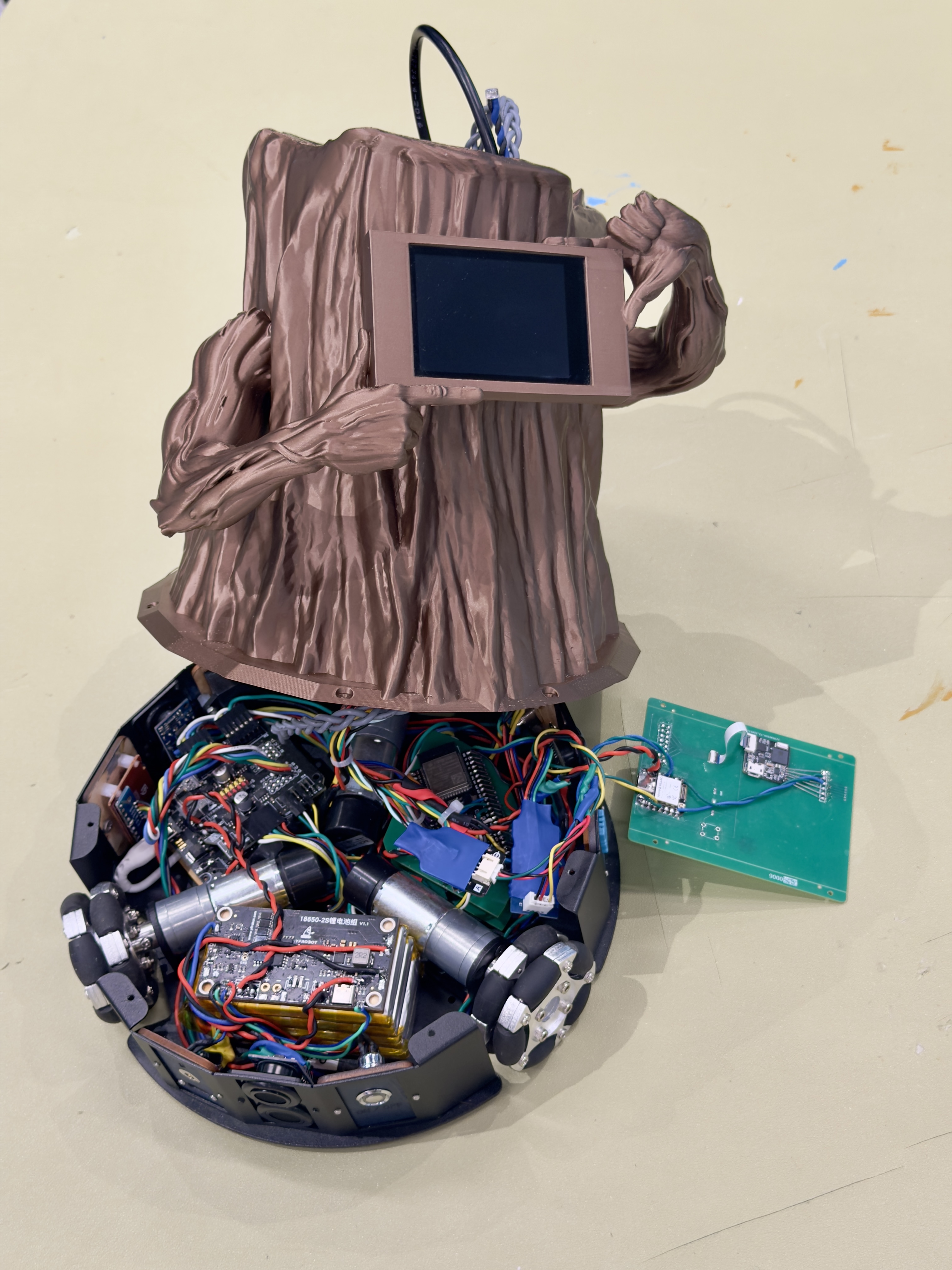
The first packaging sketch mattered because the body has several layers: plant pot, electronics space, mobile base, and charging area. I placed the sensors near the plant where their readings make sense. I placed the screen on the front face because that is where the user looks for dialogue. I kept battery, switch, and charging contacts toward the rear so I can reach power without removing the plant.
Step 3: integrate the input devices
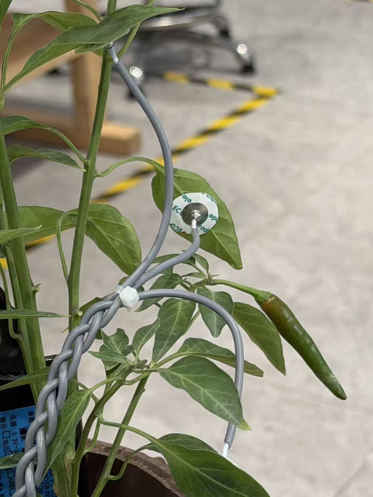
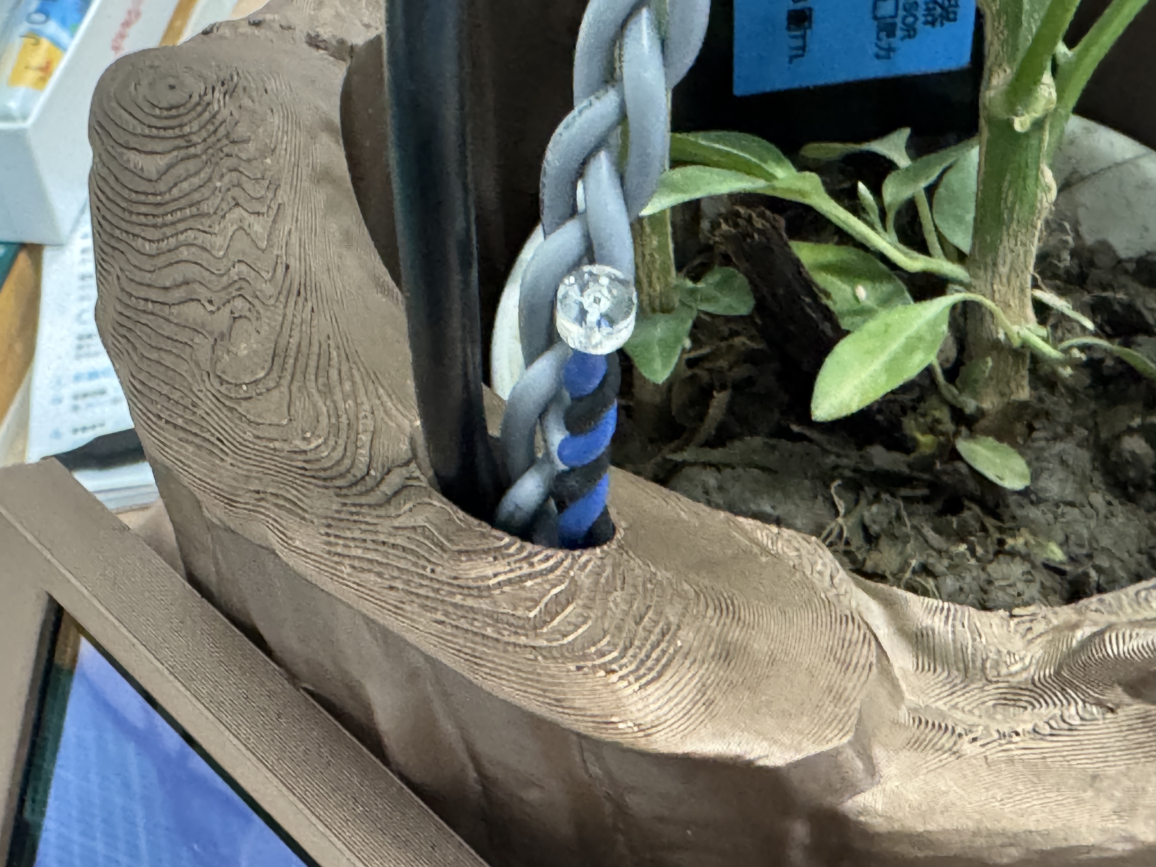
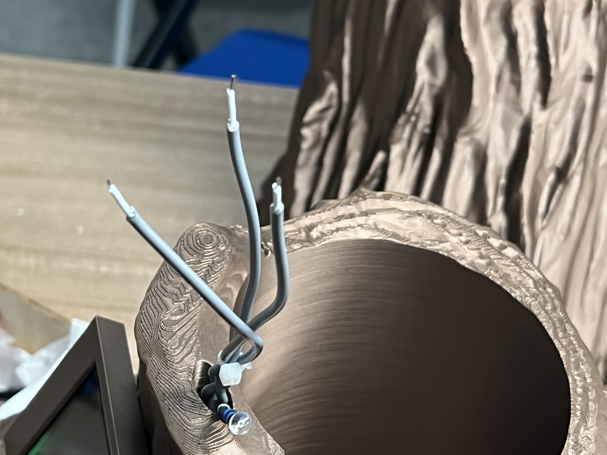
For input devices, I separated "human input" from "plant input." Human input is mainly the microphone / cloud path for open speech. Plant and environment input is distributed around the pot: light, DHT11, soil sensing, and leaf-side impedance electrodes. The reason for placing those sensors close to the plant is practical: if the wire path is too long or loose, I may be measuring the robot layout more than the plant.
Step 4: integrate the output devices
The main output device is the ST7789 display. It gives the plant companion a readable front face: status pages, dialogue text, and test feedback. The speaker is the second communication output through the cloud TTS path. Motion and charging lights also count as outputs here, because they show what the physical robot is doing, not only what the screen is saying.
Step 5: route wiring and power
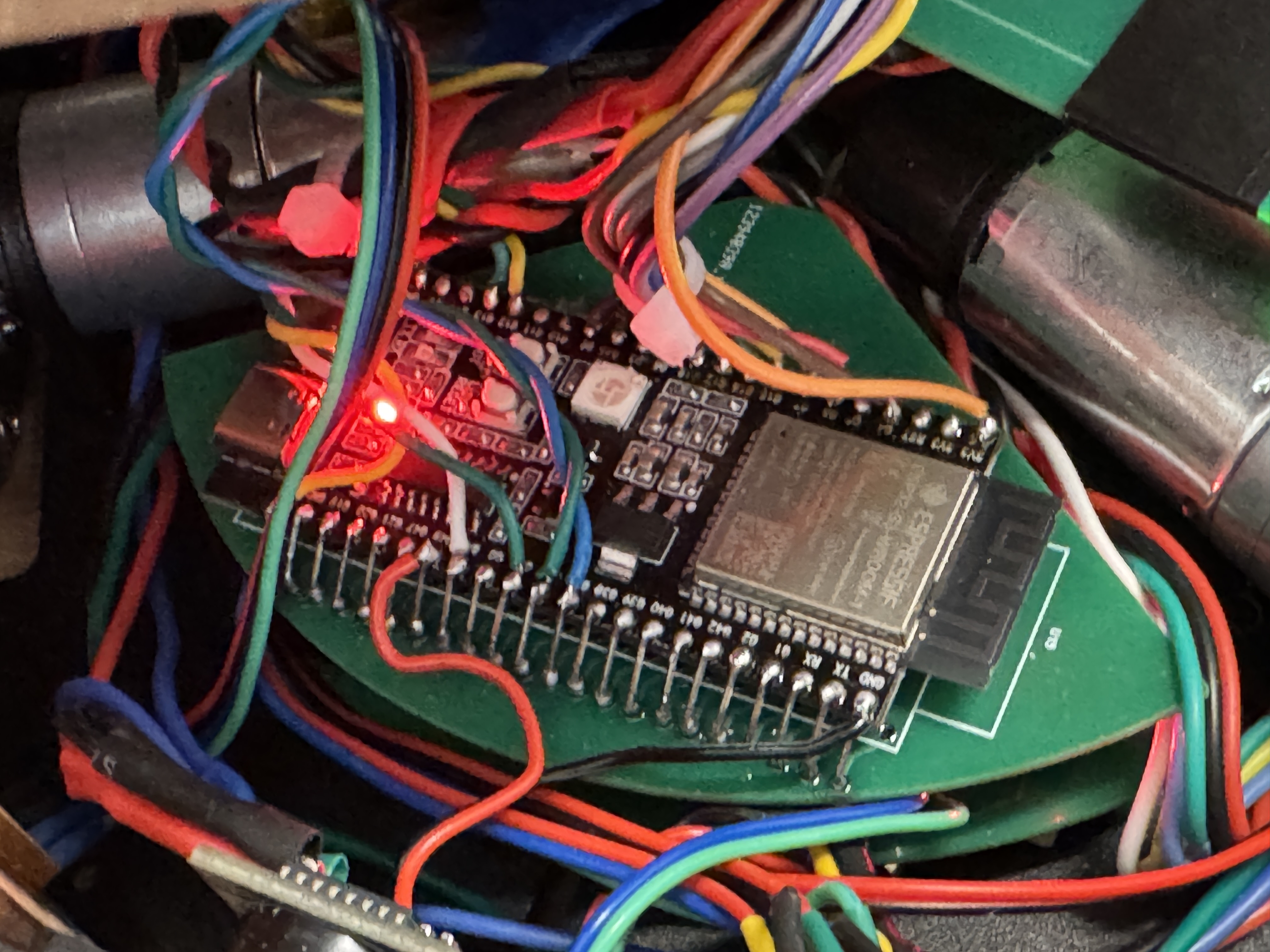
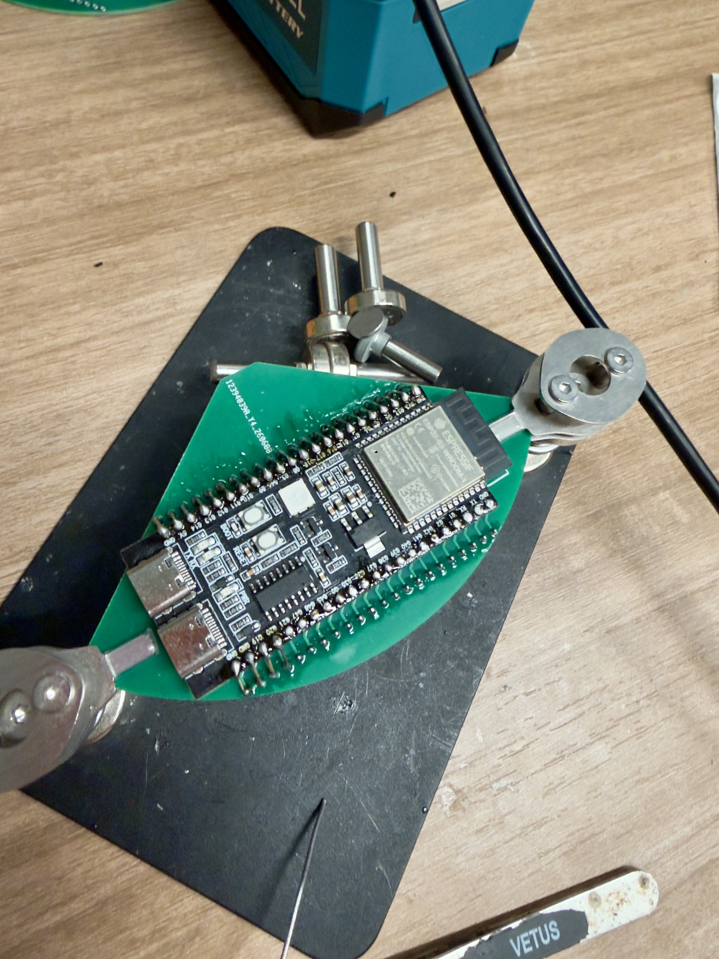
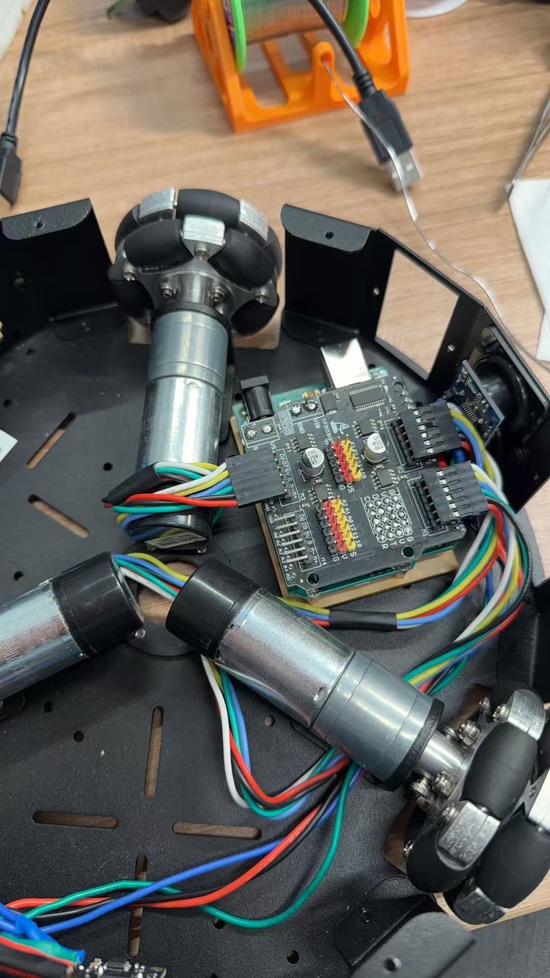
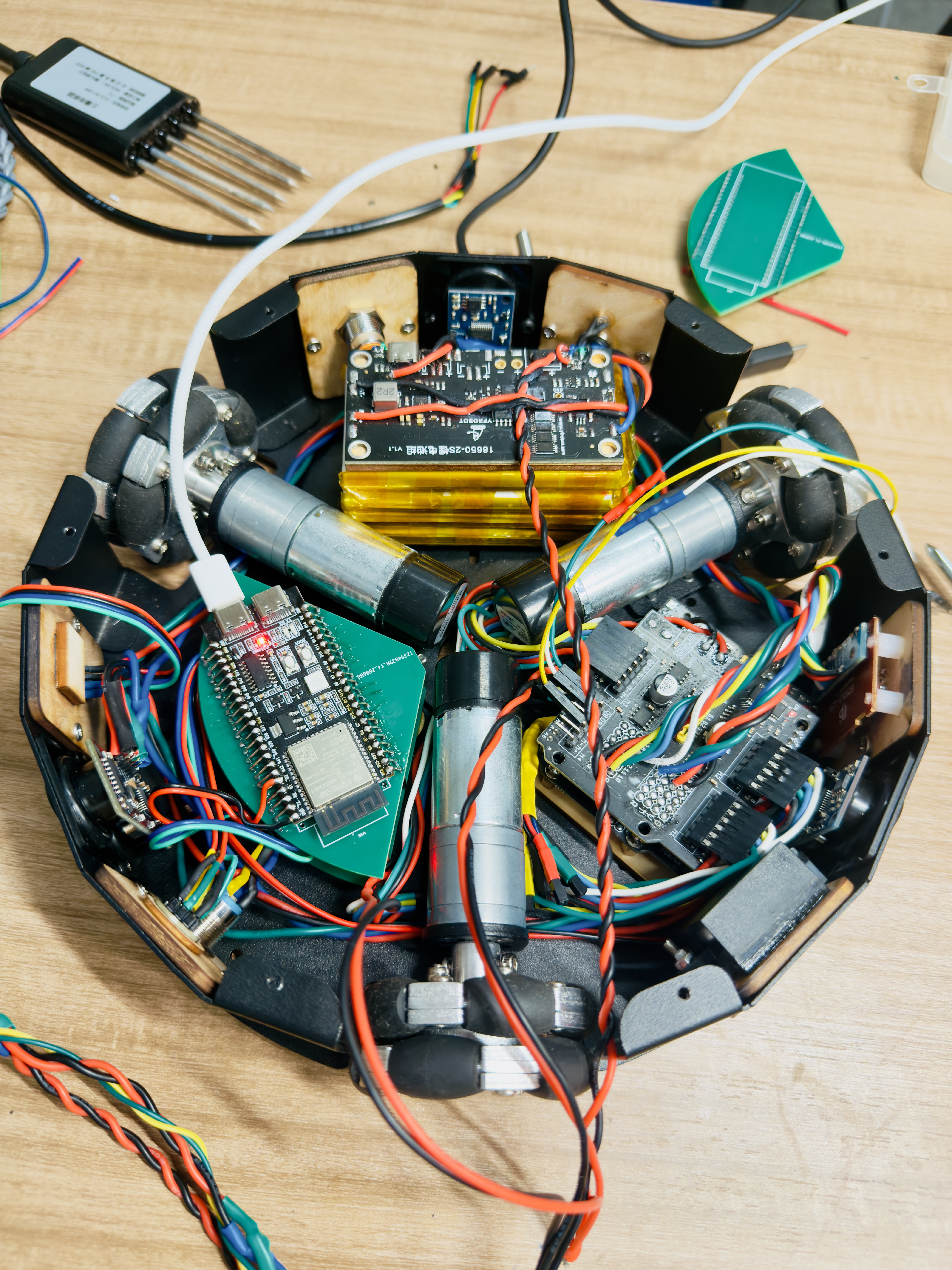
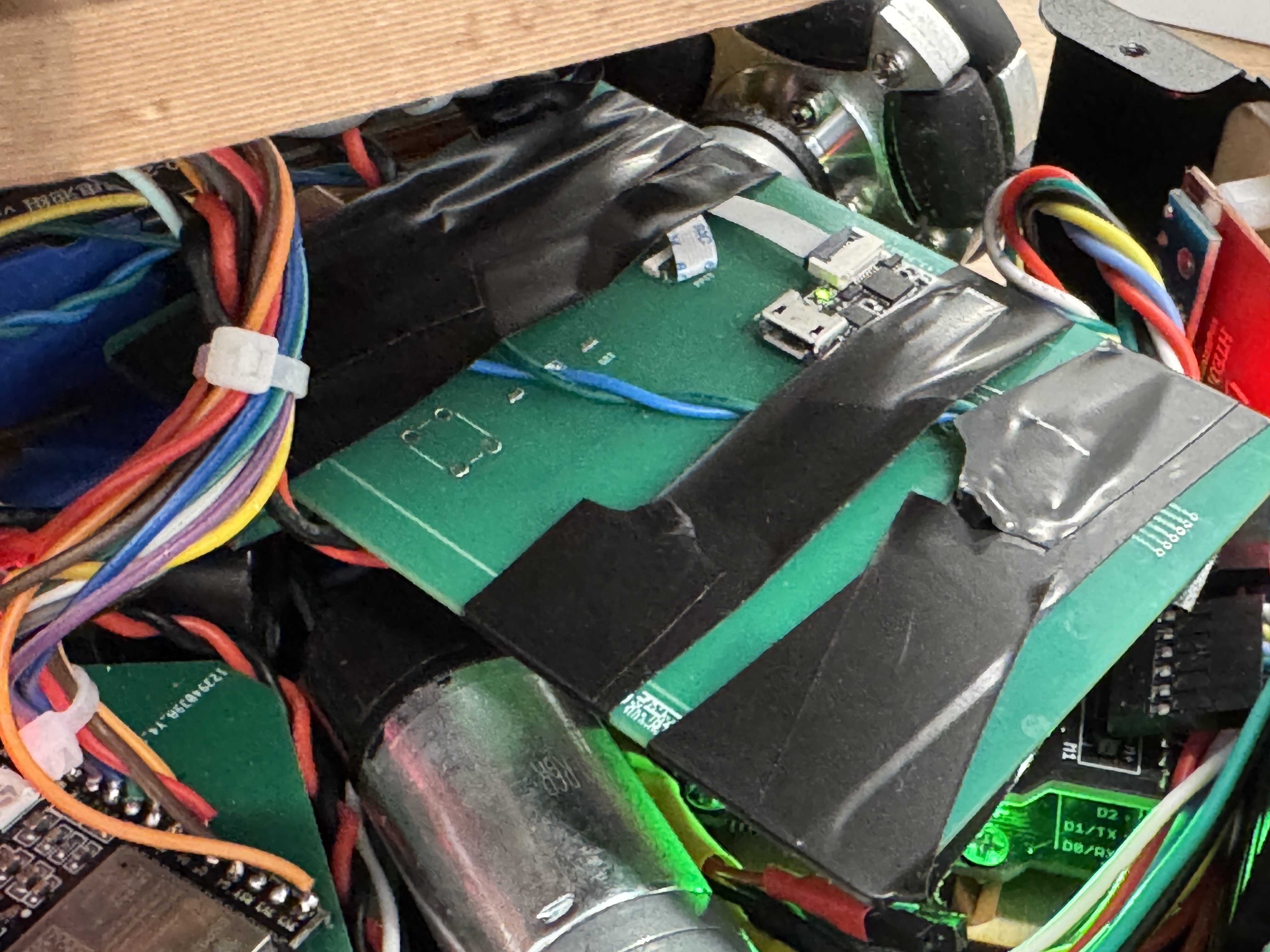
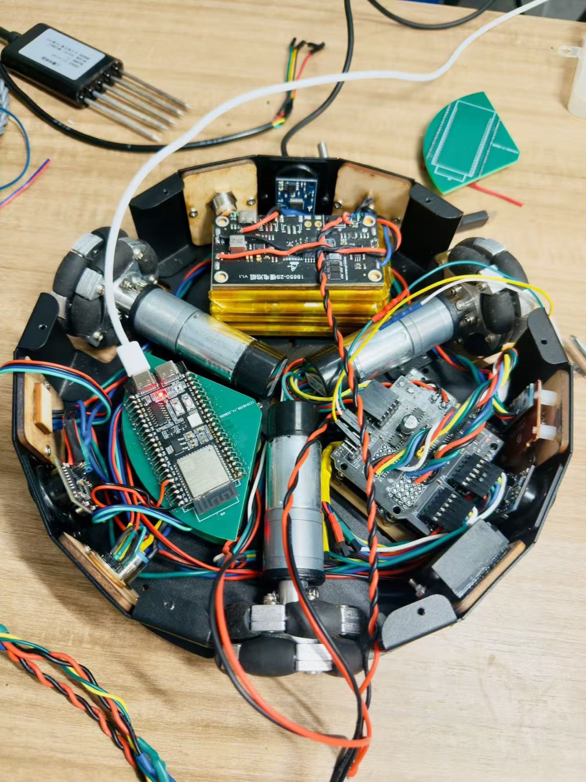
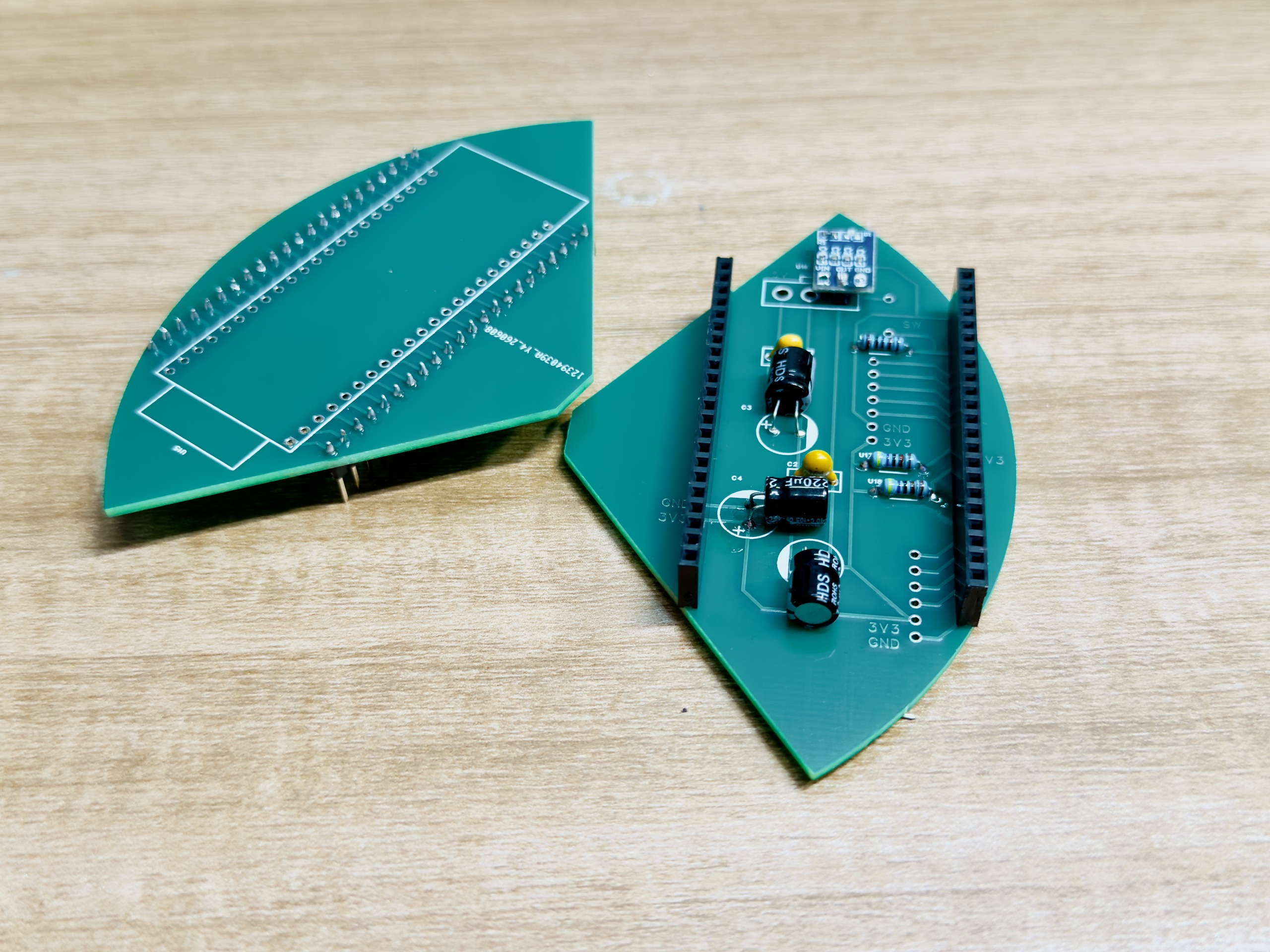
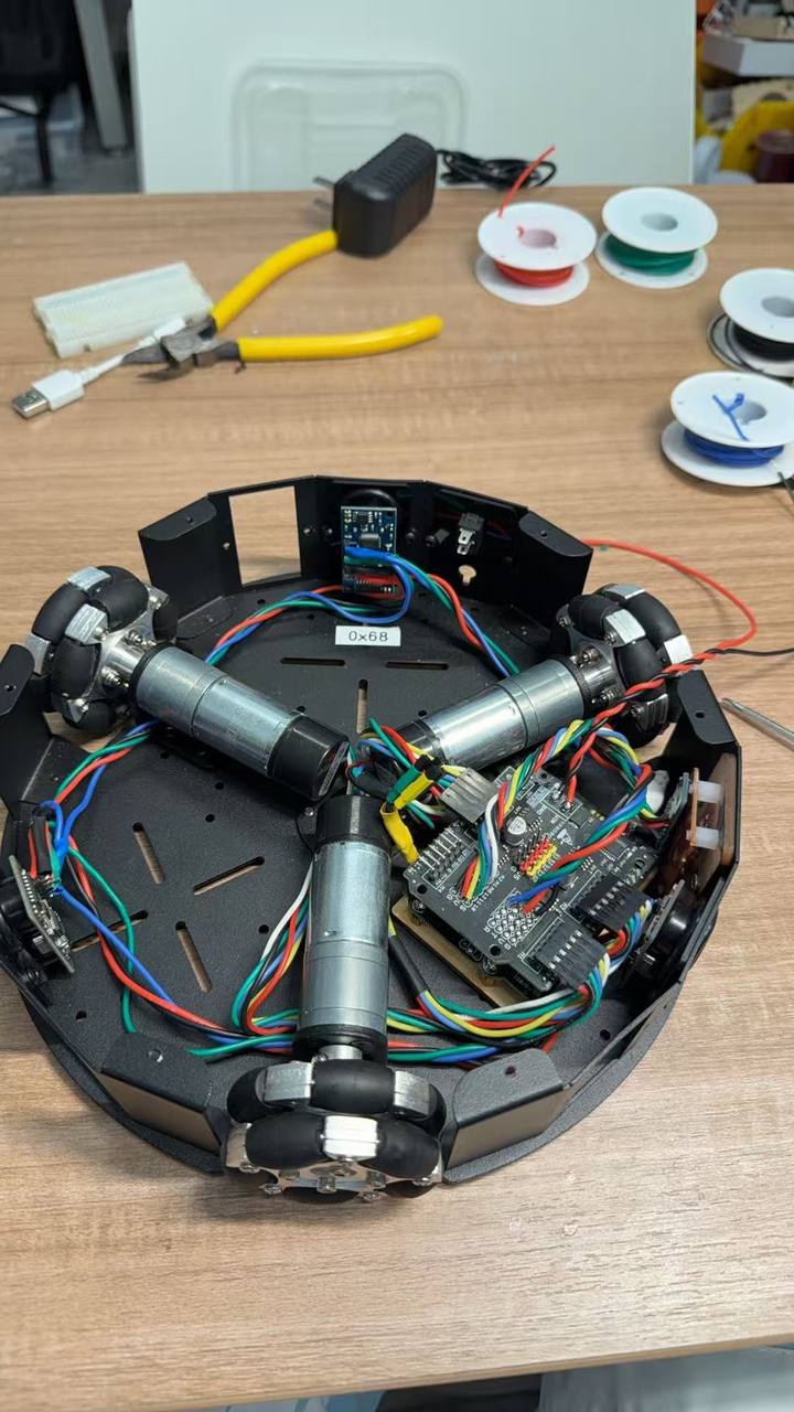
This was the part where the project stopped being a drawing. I fixed boards inside the chassis, shortened or tied wire groups where possible, and kept the wires inside the shell instead of wrapping them around the outside. The UNO is fixed with screws. The WROOM PCB and battery use spacers / glue so they do not float in the moving base. Some connections stay as headers for service, while sensitive or final connections are soldered and protected.
Step 6: display power vs I²C pull-ups
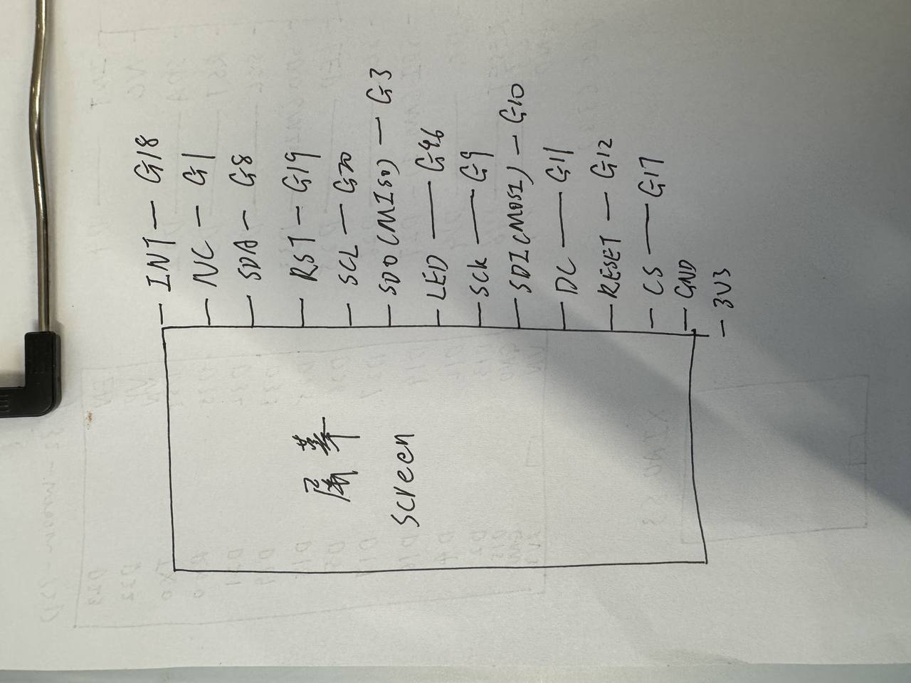
One debug issue changed how I wired the system: a striped display pushed me to check display power separately from I²C pull-ups. In a multi-board build, a screen fault can be power or bus related, not only graphics code.
Step 7: assemble and test as one product
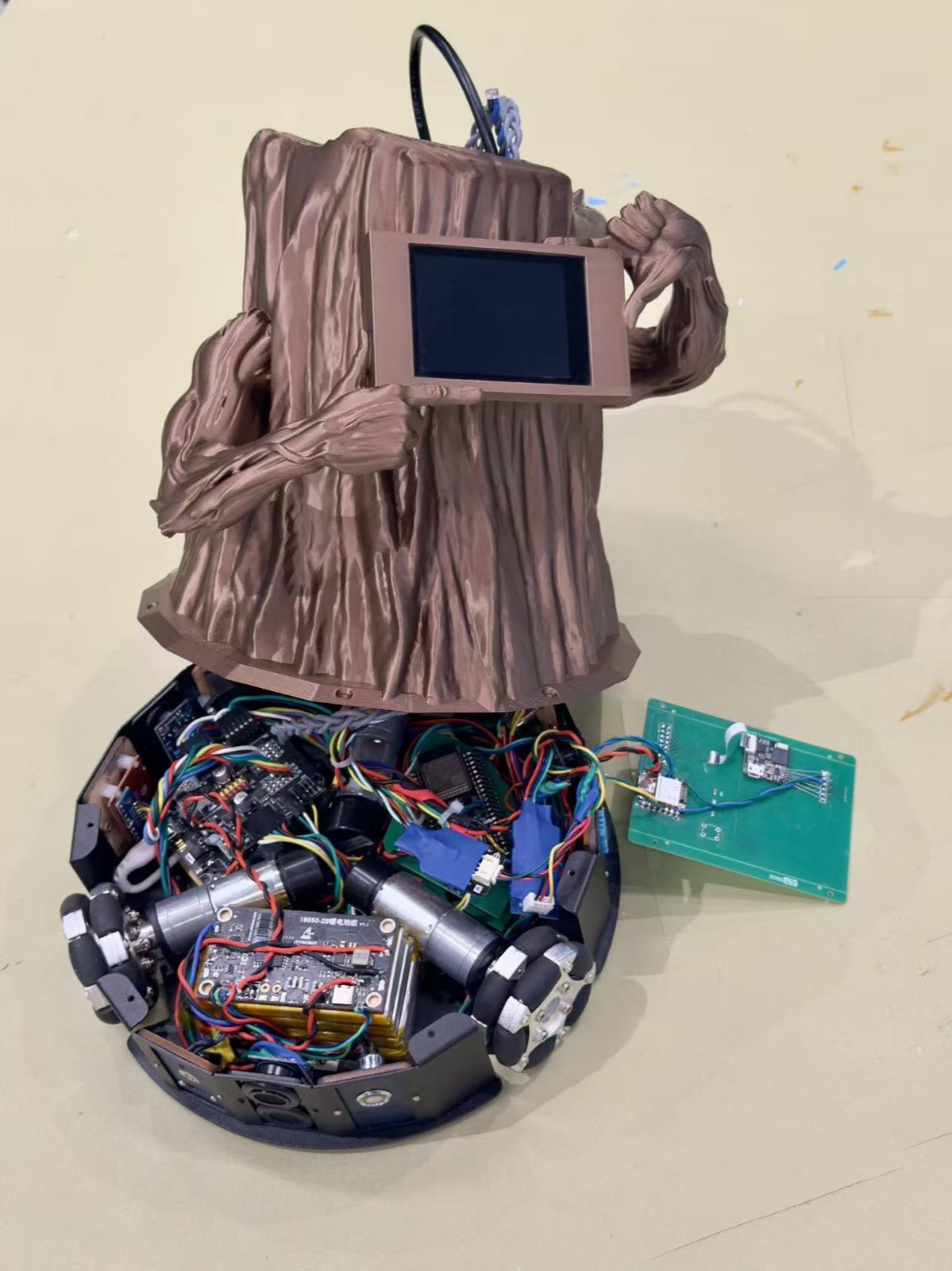
The final check is whether the project reads as one object: flowerpot, base, screen, battery, wires, sensors, voice path, and charging contacts in the same body. I also checked the system integration requirement: every part has a place and the combined function is visible to a user.
Files and notes for checking later
I kept the main code and notes linked so I can check the build later. The cloud voice files are archived in
code/week17-individual/, and the complete final upload tree is in
code/final-project-upload/wroom-upload/.
I used Cursor to code and refactor the WROOM display, XIAO hub, and Bailian voice client files linked above while I closed the chassis. I still re-ran each upload after wiring changes and checked display power separately from I²C before trusting the integrated demo.
My main takeaway: the hard part was not one more feature. It was making each part sit in the right place, deciding which board reads each input, which device gives each output, and where each wire travels. The cloud voice path gave me natural interaction for Forest Fairy; the final assembly put that interaction inside one physical body.