Week 7: Computer-controlled machining
Computer-controlled machining week. For my individual assignment I designed a flat-pack little dog bed, exported 2D joint geometry as DXF, generated toolpaths in Mastercam X6, and cut the parts on the lab wood CNC (TC1325B). This page documents design intent, CAM settings, the machine workflow, assembly, and downloadable source files. The group section holds the TC1325B safety and operating procedure we wrote in the lab.
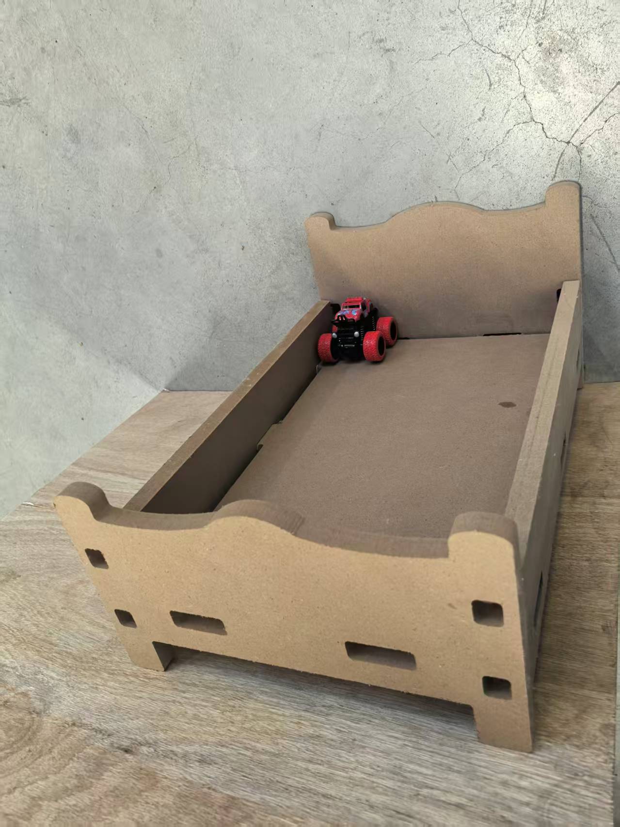
Individual assignment: little dog bed (design + CNC + assembly)
Why a dog bed
The Fab “make something big” brief pushes you to think at furniture scale: joints, sheet nesting, and a machine that can hurt you if you treat it casually. I wanted an object that was personal but still forced me through the full loop: 2D CAD → CAM → fixturing → cut → dry-fit → assemble. A small dog bed fit that: flat panels with visible joinery, a curved headboard and footboard for character, and a finished piece I could actually use at home instead of a throwaway test bracket.
I measured our board stock at about 18.2 mm and designed the slot-and-tab joints around that thickness rather than assuming “18 mm on the label.” That single number drove every pocket width and every clearance decision later in Mastercam.
How this page meets the assignment
Mapping to the Fab Academy computer-controlled machining checklist:
| Requirement | Evidence on this page |
|---|---|
| Linked group assignment | Group section (TC1325B procedure and safety) |
| Documented object design | Design (flat-pack panels, 18.2 mm joints) |
| Documented CAM / toolpaths | Mastercam X6 (contour ops, tool, feeds) |
| Documented machining (fixturing, feeds, depth, joints) | CNC cutting (setup photos and video) |
| Problems and fixes | Lessons |
| Design files + finished photo | Downloads; assembled bed |
Design: flat-pack panels and joints
I modeled the bed as separate 2D profiles meant to be cut from one sheet and assembled with press-fit slots: two end panels with curved tops (headboard and footboard), two long side rails with matching notches, and a rectangular base platform. Every slot is sized for 18.2 mm material, the measured thickness of our density board, so the tabs on the crossing members should slide in without guessing at the label thickness.
The curved silhouette on the end panels is decorative but still CNC-friendly: outside contours and interior pockets only, no impossible inside corners without planning for tool radius. I exported the layout as DXF for the lab CAM station rather than trying to post G-code myself on the first pass.
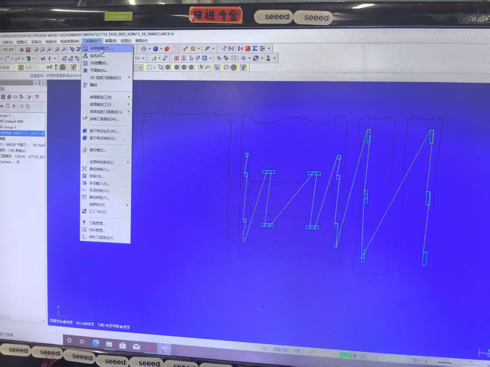
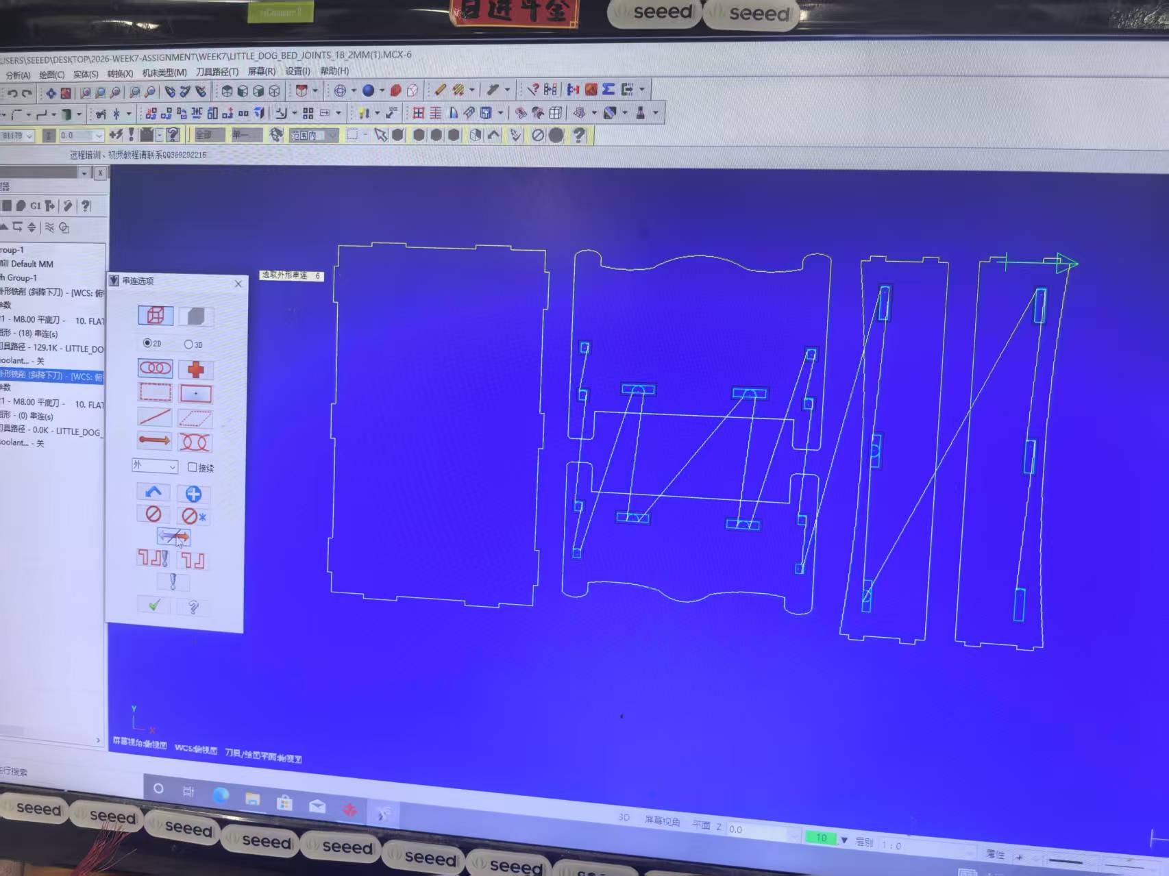
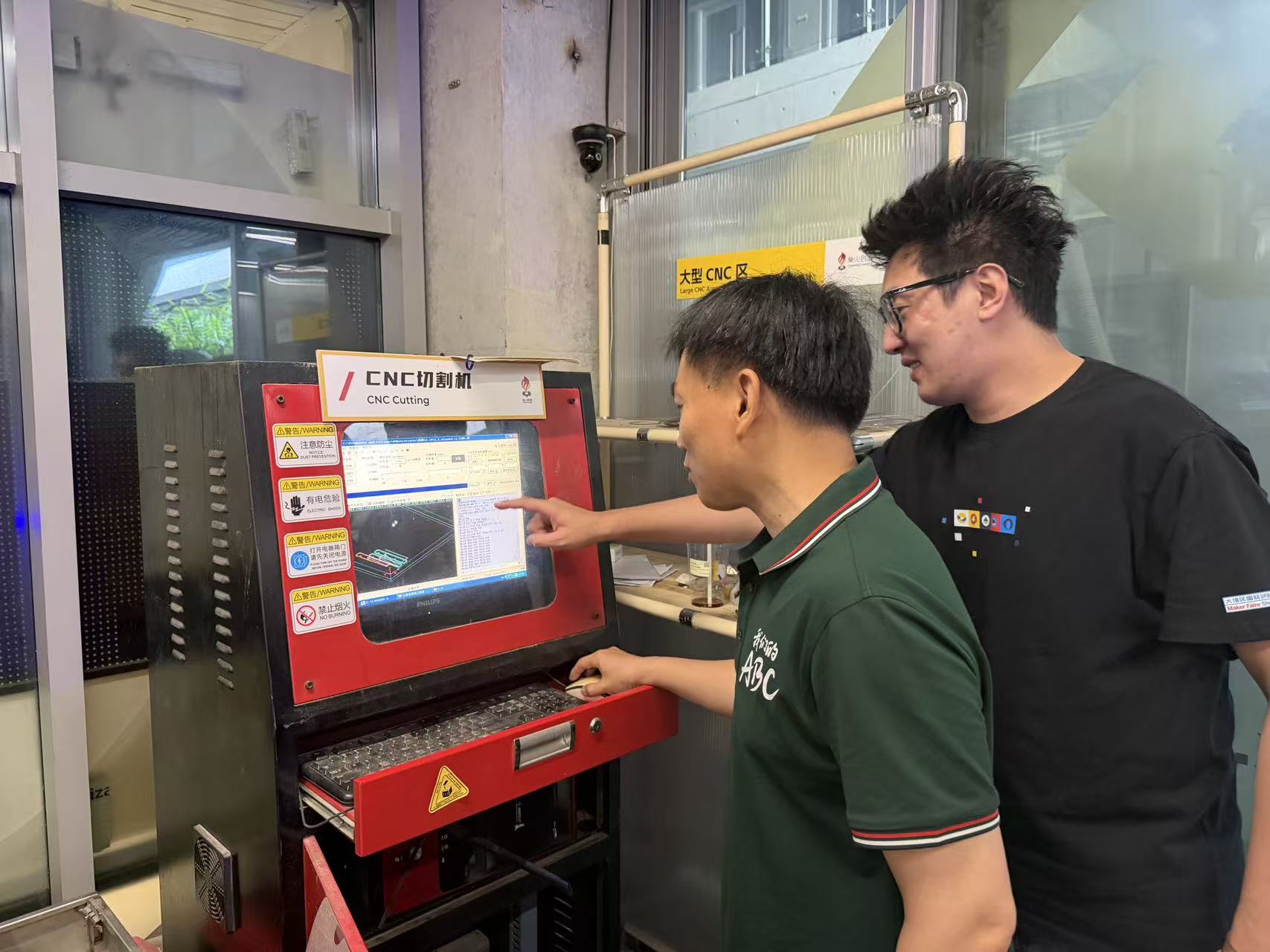
CAM: Mastercam X6 toolpaths
At the lab we opened the DXF in Mastercam X6, defined the stock, and built 2D contour toolpaths for the outlines and joint pockets. I watched the sequencing closely because this was the first time I saw how “inside before outside” keeps the sheet stable while small features are still tied to the parent panel.
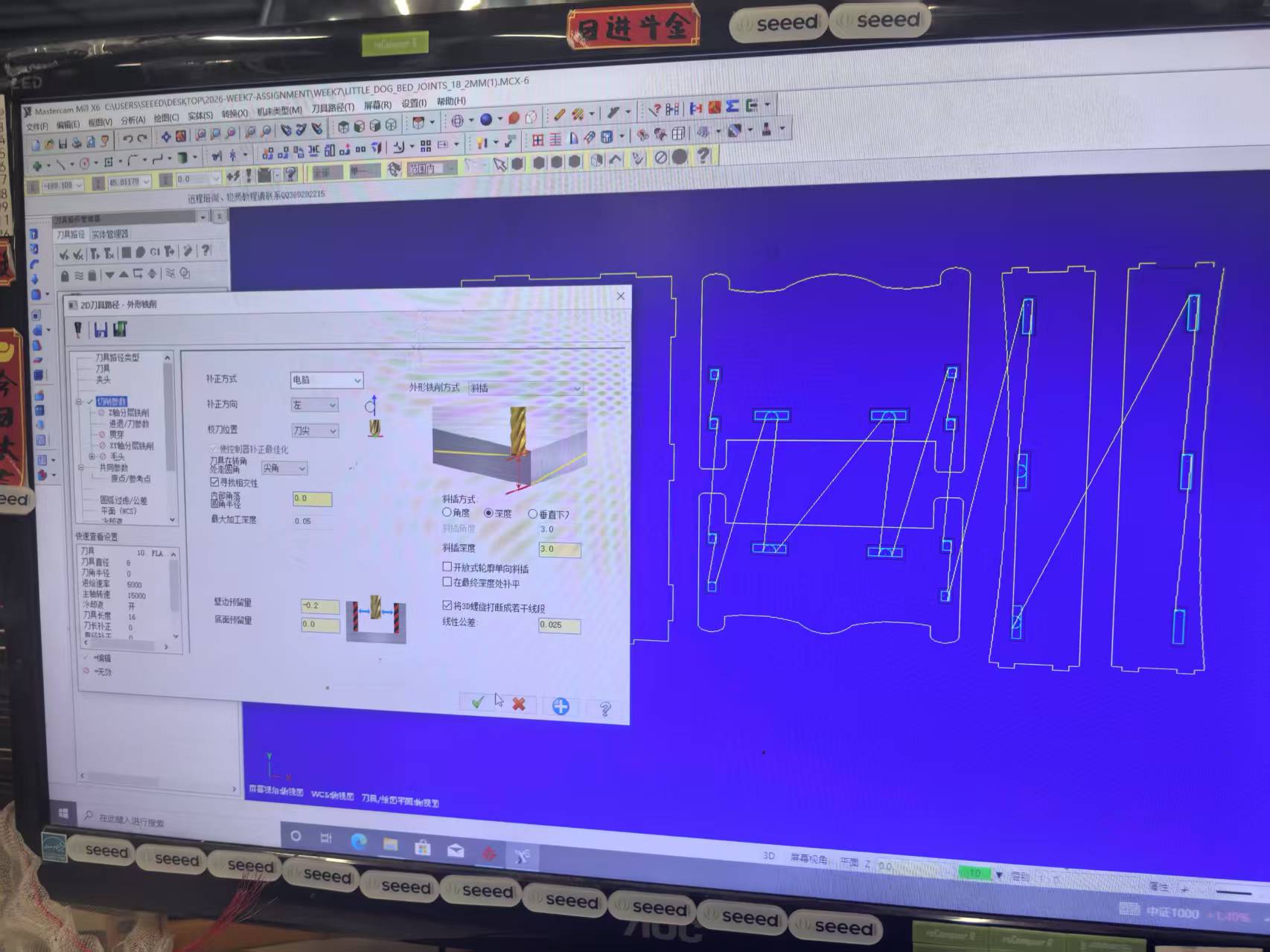
I wrote down the CAM settings while the file was still open because they explain the fit later:
an 8 mm flat end mill (#1 — M8.00 FLAT in the toolpath
manager), 15 000 rpm spindle speed, 5 000 mm/min
feed, 2D contour / 外形铣削 with step-down entry, computer compensation on the
left, −0.2 mm wall stock for joint clearance, and a
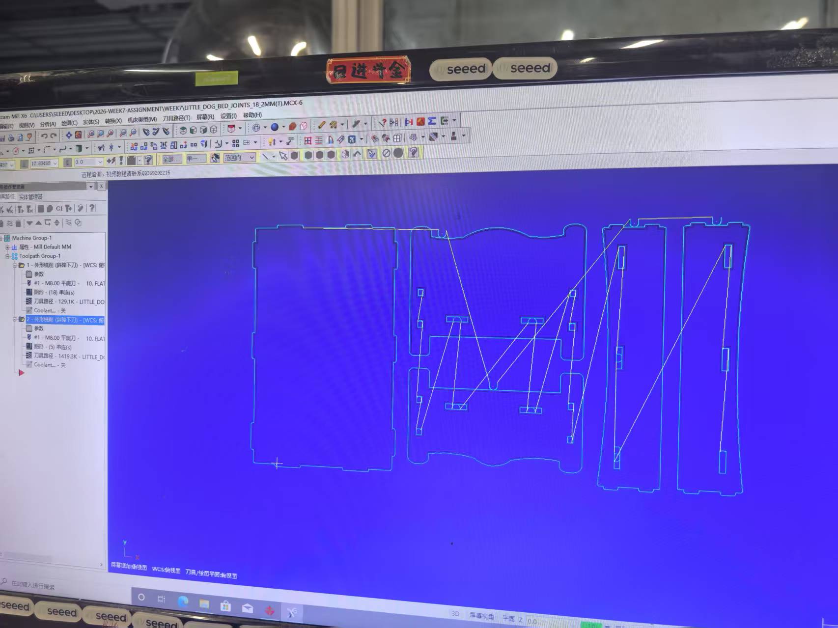
3.0 mm ramp depth on contour entry. We split the job into two contour
groups: 18 chained loops for interior features and details, then 5 chained loops for the final
outside separation. The negative wall stock was the detail I did not appreciate until assembly:
a hair of extra width on slots makes press-fit parts actually go together after a real bit radius,
without redrawing every pocket in CAD.
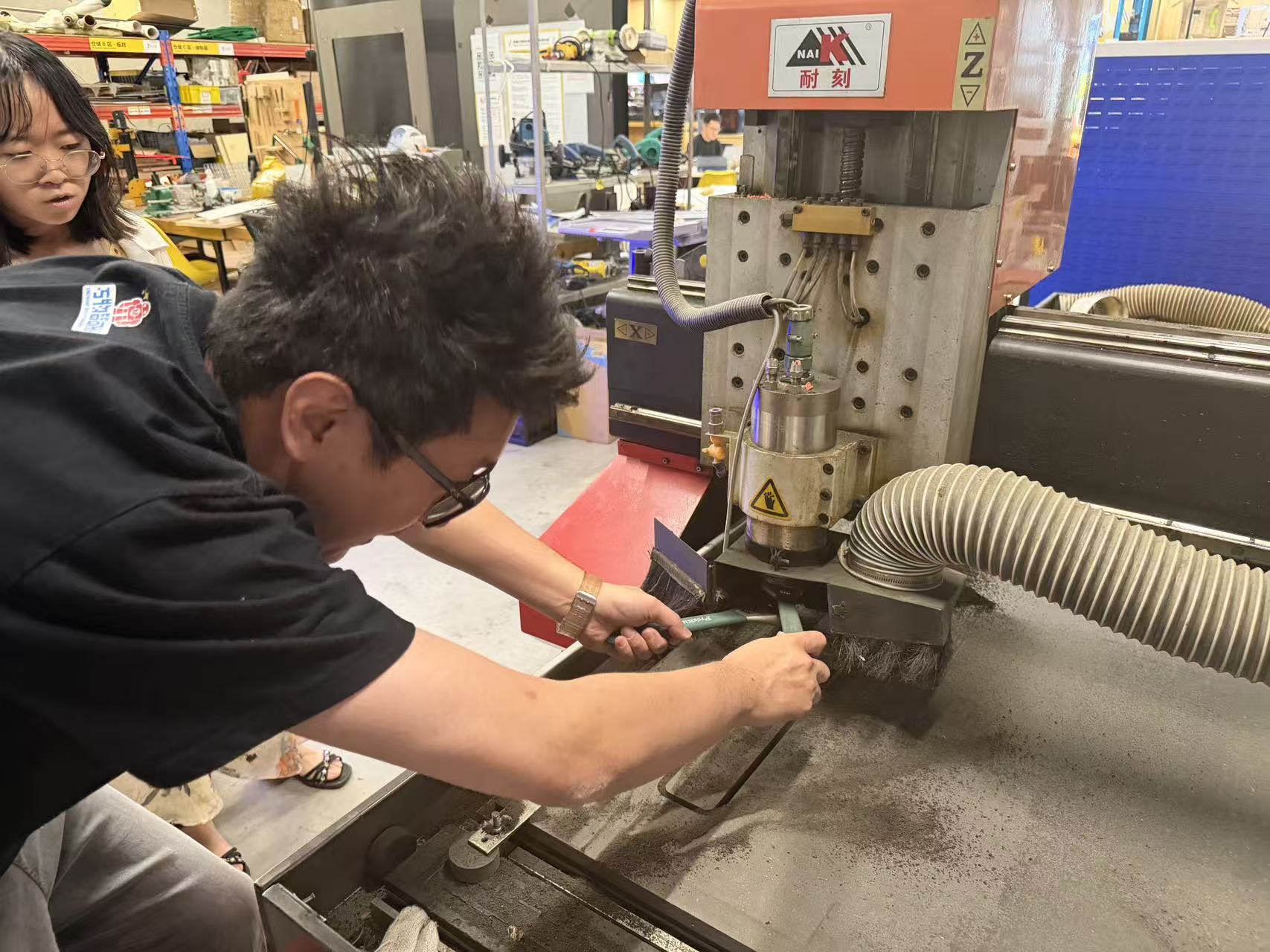
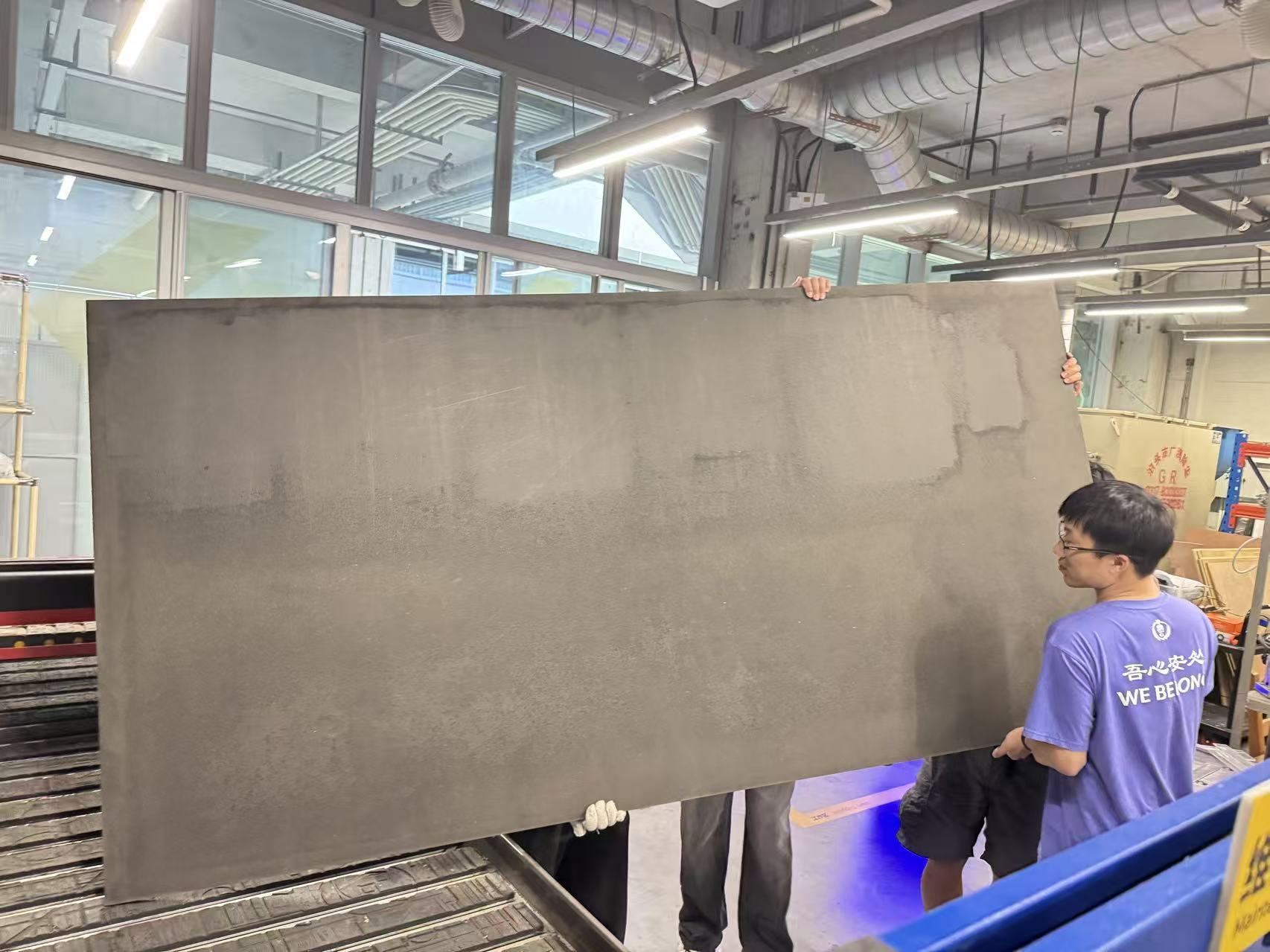
CNC cutting: machine setup and run
I followed the same TC1325B sequence documented in the
group assignment, but this section is my own job: loading the posted
.NC file, fixturing the panel, setting work zero, and supervising the cut through to free parts.
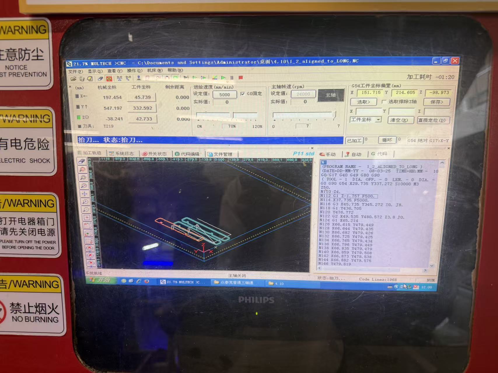
The controller preview showed the nested bed outlines before we started the spindle.
1. Load G-code

2. Place and clamp the panel


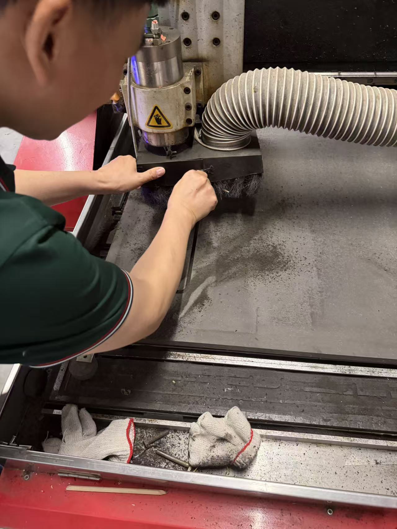
3. Tool, guard, and Z setup


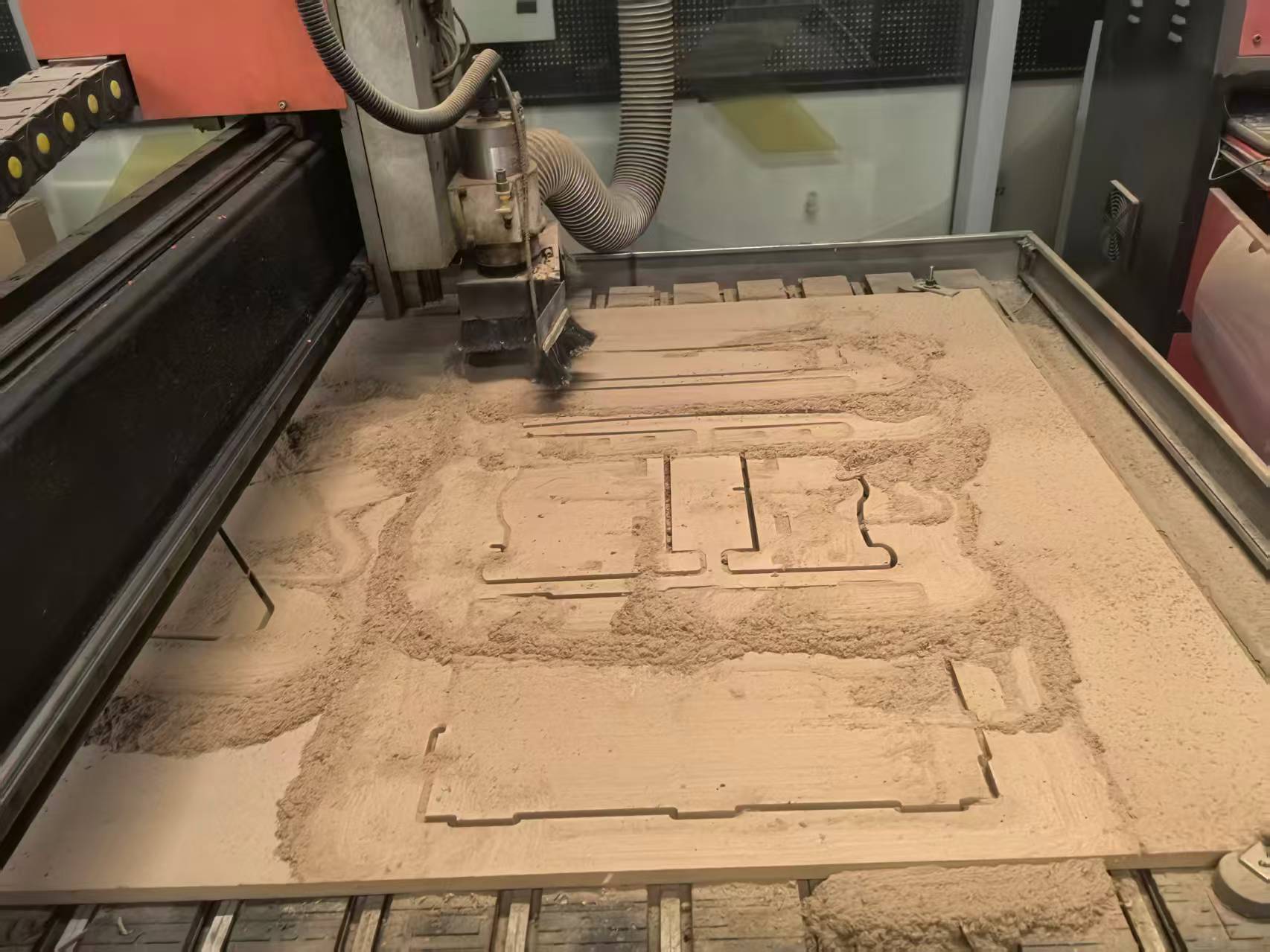
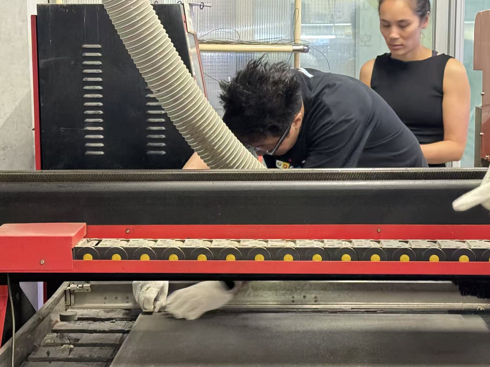
4. Run and monitor
I stayed at the machine for the full job, dust extraction on, listening for chatter or loose parts. When inner pockets finished before outer contours, the sheet still had enough connection to stay put. That is why we sequenced small/internal cuts first in CAM.
Assembly
After breaking parts out and brushing off chips, I dry-fit the rails into the end panels, then pressed the base platform into the slot grid. The −0.2 mm CAM wall stock was enough that I did not need aggressive filing, though I still checked each inside corner where the round bit left a small radius.
Problems, checks, and what I would change
The biggest lesson was to design from the measured material, not the label. If I had modeled the joints at “18 mm,” the real 18.2 mm board would have made the fit too tight, so next time I will keep sheet thickness as a named parameter in the CAD file. I also learned that clearance belongs in CAM, not in guessing: the −0.2 mm wall stock did more for the final fit than redrawing slots by eye, although I would still cut a small test pocket before spending a full sheet. Watching the job run made the cut order make sense too; interior pockets before outer contours kept the panel stable, which is why Alison's write-up stressed “inside to outside, small to large.” The last point is less elegant but more important: long outer passes throw a lot of MDF dust, so extraction stays on and I stay at the pause / E-stop station until the spindle is done.
Design files (download)
Source geometry and the posted program from this run. Save the file explicitly if the browser previews text instead of downloading.
Reference walkthrough with a similar chair workflow: Alison Yang, Week 7 documentation.
Group assignment
Guangzhou (Chaihuo) group documentation: wood CNC operating procedure and safety (TC1325B).
Wood CNC engraving machine: operating procedure and safety
Equipment: TIANCHENG XINLI Wood CNC engraving machine
TC1325B
Manufacturer: Shenzhen Tiancheng Xinli CNC Equipment Co., Ltd.
Overview: This is the three-axis wood CNC we used for panel cutting. It removes material fast enough that setup mistakes become dangerous, so we relied on the machine nameplate, factory manual, and on-site training for X/Y/Z travel, spindle power, maximum speed, and control system type. The “1325” designation usually means a larger-format panel-style router; specifications may vary by batch or custom configuration.
I. Operating procedure (recommended order)
We followed this order at the machine: prepare the workpiece and tool, establish coordinates and height, then run the program.
1. Load G-code into the machine
- Transfer the program to the CNC controller via USB drive, network, or host software.
- Open the file on the controller. Check the program name and any displayed estimates (time, line count). Confirm that the active work coordinate system (e.g. G54) matches the zero point you set on the machine.
2. Place the workpiece (wood panel)
- Clean the table and the bottom of the workpiece so chips do not cause rocking or gaps.
- Place the panel within the machine’s usable travel (check the nameplate or manual for work envelope). Leave clearance for the tool and fixturing.
- Ensure the cut area is supported (vacuum table, blocks, or clamps) to avoid chatter, tool breakage, or unsupported cuts. Large panels: check table load capacity and flatness.
3. Secure the workpiece (fixer / clamps)
- Use toe clamps, a vise, dedicated fixtures, or the lab-approved fixer. Clamping must be firm and must not interfere with the toolpath.
- Keep bolts/clamps low relative to the machined surface, or verify the path clears them; use low-profile clamps or side clamping if needed.
- After clamping, push the workpiece lightly to confirm it cannot shift.
4. Change the tool (cutter)
- Only install or remove tools when the spindle is fully stopped and the machine is in a safe state (e.g. program stopped or emergency stop as required by your site rules).
- Install per the collet/chuck type; tighten to the specified torque. Check stick-out: enough for the cut, not so long that rigidity suffers.
- If dust collection or a guard is used, check clearance between tool length and the shroud.

5. Close the spindle guard / dust hood
- Install and latch the spindle guard, viewing cover, or dust port to limit chip throw and entanglement.
- Confirm the guard cannot collide with clamps or the workpiece anywhere in the travel.
6. Set the work coordinate zero on the machine
- Common methods: touch plate, edge finder, or trial cut to set XY at a agreed corner of the panel (must match the CAM part origin).
- Z zero is often on the top of the stock or the table top, per CAM; a mismatch causes wrong depth or a crash.
7. Adjust height (Z axis and tool setting)
- After setting XY and Z in the work coordinate system, move the tool to a safe clearance height.
- If you use a touch plate or gauge block, follow the manual for tool length offset or Z confirmation.
- Before the first run of a new program, raise Z and dry-run the path, or run in single-block mode, to verify motion.
8. Start cutting
- Operator in position; wear required PPE (see below).
- Close or verify all doors/covers per procedure; start the spindle to the program speed if not commanded by the program.
- Run the program. Stay at the machine; listen for abnormal noise and watch chips and dust. On any fault, hit emergency stop immediately.
II. Safety during use
(A) General
- Read and follow the manufacturer’s safety chapter and your lab or shop rules.
- Wear safety glasses; use a dust mask when fine dust is produced, and confirm dust collection or exhaust is connected and working.
- Tie back long hair; no loose clothing, scarves, or gloves near a rotating spindle (gloves can be pulled in).
- If you are unsure of a program, use single-block, dry run, or reduced feed override first.
(B) Mechanical / motion
- Before cycle start, ensure no hands, tools, or rags are inside the envelope; keep the table clear.
- Never reach into the machining zone while the machine is running. To clean or adjust, stop the spindle, then stop the program or E-stop, and wait until everything is still.
- Know where the emergency stop is and that you can reach it at all times.
(C) Tool and workpiece
- An improperly secured tool can eject at high energy. Recheck after installation.
- Loose fixturing can shift the part, break tools, or eject the workpiece; recheck clamps at the start of a session or before long runs.
- Excessive depth or feed risks broken tools and flying fragments; start conservative for material and tool, then tune.
(D) Electrical and dust (woodworking)
- Do not touch electrical parts with wet hands; route cables away from moving parts and heat.
- On the TC1325B, sawdust and fines increase slip and fire risk: clean the table and floor; keep dust hoses clear; no open flame nearby; follow local fire rules.
(E) Program and coordinates
- Mismatched zero, tool length, and stock thickness versus CAM is a common crash cause; after any tool change, reload, or workpiece move, re-touch off or re-verify Z.
- After editing G-code, re-check units (inch/mm) and that safe clearance heights are present.