Week 11 — Networking and communications
Fab Academy
Networking & Communications
week: our group exercised BLE and I²C on two XIAO ESP32C3 boards (
below). For my
individual assignment I wired a three-node chain for the
Forest Spirit / 森之精灵 plant companion: a NanoStat front-end on
ESP32 Pico talks to my Seeed XIAO ESP32‑S3 hub over
UART; the hub (on my Week 8 carrier) forwards plant status and Week 9
environmental reads to an ESP32‑S3 WROOM display module over I²C
(HostLink slave 0x55). Week 10 already proved the XIAO → WROOM
0x01 telemetry path; this week adds the Pico → XIAO serial hop and the
0x07 plant frame to the TFT Plant info page.
Individual assignment: UART hub + I²C display chain
Per
Networking & Communications
I had to connect wired or wireless nodes that each have a bus address and a local input or
output, then show that the links work. I did not make a new PCB this week. I used the
Week 8 JLCPCB hub from
Week 6 rev. 2 (NanoStat UART pads were already
in that revision), plus two commercial satellite boards (Pico NanoStat stack, Senlin WROOM +
ST7789). Evidence is wiring, serial/I²C logs, and firmware in
code/week11-network/ (trimmed from my
Downloads bench trees).
1. Task
My final project splits plant impedance, room environment, and human-facing UI across MCUs so analog experiments and SPI/TFT work do not fight for the same pins. Week 11’s job is to make that split communicate on the bench:
-
Node A: Pico + NanoStat input: measures impedance through the
LMP91000 front-end, classifies nitrogen stress locally, and outputs one ASCII line per
sample on UART TX (
STAT,…at 115200 8N1). -
Node B: XIAO ESP32‑S3 on my Week 8 PCB:
inputs DHT11 + light (Week 9) and UART RX from Pico;
outputs I²C master writes to WROOM at address 0x55
(
cmd 0x01environment,cmd 0x07plant status). - Node C: ESP32‑S3 WROOM display: I²C slave 0x55, output ST7789 TFT — Environment page for RH / °C / light ( Week 10) and Plant info for level / N-index from Pico.
The data path I am proving matches my product README (
PICO上传程序 → S3上传程序 → WROOM上传程序 in Downloads):
PICO (STAT lines)  --UART 115200-->  XIAO S3 (parse + bridge)
XIAO S3            --I2C 0x55-->     WROOM (ST7789 UI)
System map: three nodes, two protocols
| Node | MCU / board | Local I/O | Link | Address / framing |
|---|---|---|---|---|
| A | ESP32 Pico (NanoStat) | LMP91000 + electrodes (input) | UART → XIAO | Async serial; line-oriented STAT,…\n |
| B | XIAO ESP32‑S3 (Week 8 PCB) | DHT11, light ADC (input); I²C master (output) | UART ← A; I²C → C | Slave select 0x55; 8-byte HostLink frames |
| C | ESP32‑S3 WROOM + ST7789 | TFT (output) | I²C ← B | 7-bit 0x55; cmds 0x01, 0x07 |
Final upload firmware notes
Instructor feedback asked for the actual sketch, clearer code explanation, bus addresses, TX/RX pins, and a
connection diagram. The complete final upload firmware is archived in
code/final-project-upload.zip, and the browsable source trees are
s3-upload/,
wroom-upload/,
pico-upload/, and
uno/. The excerpts below are copied from that final
upload set. I pulled the excerpts below because they are the parts I used to check the communication paths.
flowchart LR
  Pico["Node A: ESP32 Pico + NanoStat
Plant impedance status"]
  Xiao["Node B: XIAO ESP32-S3 hub
DHT11 + light + bridge"]
  Wroom["Node C: ESP32-S3 WROOM UI
ST7789 + FT6336"]
  Tft["Local output: ST7789 TFT
SPI 26 MHz"]
  Touch["Local input: FT6336 touch
I2C addr 0x38"]
  Soil["Soil probe
UART Modbus addr 0x02"]
  Uno["Arduino UNO motion base
UART text protocol"]

  Pico -- "UART 115200 8N1
Pico GPIO1 TX to XIAO D7/GPIO44 RX
ASCII STAT lines" --> Xiao
  Xiao -- "I2C master 100 kHz
SDA D4/GPIO9, SCL D5/GPIO8
HostLink write to slave 0x55" --> Wroom
  Wroom -- "SPI
SCK18 MOSI8 MISO16 CS9 DC3 RST46 BL17" --> Tft
  Touch -- "I2C 100 kHz
SDA6 SCL15, addr 0x38" --> Wroom
  Soil -- "UART2 9600 8N1
sensor TX to G12 RX, sensor RX to G13 TX
Modbus RTU addr 0x02" --> Wroom
  Wroom -- "UART1 9600 8N1
WROOM G45 TX to UNO G9 RX
UNO G8 TX to WROOM G35 RX" --> Uno
Connection and address summary from the final code
| Path | Protocol | Pins / address | What moves across it |
|---|---|---|---|
| Pico → XIAO hub | UART, 115200 8N1 | Pico GPIO1 TX → XIAO D7/GPIO44 RX; common GND | STAT,... text lines with plant validity, level, N-index, and reason |
| XIAO hub → WROOM UI | I²C, 100 kHz | XIAO SDA/SCL D4/GPIO9, D5/GPIO8 → WROOM GPIO37/36; WROOM slave 0x55 | 8-byte HostLink frames: cmd 0x01 environment, cmd 0x07 plant status |
| WROOM → ST7789 TFT | SPI, 26 MHz | SCK18, MISO16, MOSI8, CS9, DC3, RST46, BL17 | Local display pixels for Environment, Plant, Soil, Control, and AI pages |
| FT6336 touch → WROOM | I²C, 100 kHz | SDA6, SCL15, touch address 0x38 | Touch coordinates and swipe gestures for page navigation |
| Soil probe ↔ WROOM | UART2 Modbus RTU, 9600 8N1 | probe TXD → WROOM G12 RX; probe RXD → WROOM G13 TX; station 0x02 | Moisture, temperature, EC, salt, N/P/K, and pH registers |
| WROOM ↔ UNO base | UART1 text lines, 9600 8N1 | WROOM G45 TX → UNO G9 RX; UNO G8 TX → WROOM G35 RX | GET, SET,AUTO, SET,MANUAL, and MODE,... replies |
Shared HostLink frame format
I used a small binary frame on the addressed I²C bus so the WROOM can reject broken packets instead of
treating random bytes as plant data. Every fixed frame begins with magic 0xA5. The command byte
selects the payload type: 0x01 for environment telemetry and 0x07 for plant status.
// code/final-project-upload/wroom-upload/src/i2c_env_link.h
namespace I2cEnvLink {
static constexpr uint8_t kMagic = 0xA5;
static constexpr uint8_t kCmdTelemetryV1 = 0x01;
static constexpr uint8_t kCmdPlantStatusV1 = 0x07;
static constexpr uint8_t kSlaveAddr7 = 0x55;
static constexpr uint32_t kBusHz = 100000;

struct TelemetryPacked {
  uint8_t magic{kMagic};       // lets receiver resync to frame start
  uint8_t cmd{kCmdTelemetryV1};
  uint8_t flags{};             // bit 0 = DHT reading is valid
  uint8_t rh_percent{};
  int16_t temp_c_x10{};        // temperature in 0.1 C
  uint16_t light_pct_x10{};    // light percentage in 0.1 %
} __attribute__((packed));     // exactly 8 bytes

struct PlantStatusPacked {
  uint8_t magic{kMagic};
  uint8_t cmd{kCmdPlantStatusV1};
  uint8_t flags{};             // valid / stale / contact / range / repeat
  uint8_t level{};             // 0 normal, 1 light, 2 medium, 3 heavy stress
  uint8_t nidx{};              // nitrogen index 0..100
  int8_t dz_x100{};            // relative impedance shift scaled by 100
  uint8_t reserved[2]{};
} __attribute__((packed));     // exactly 8 bytes
}
XIAO hub sketch: establish I²C and send frames
The XIAO hub is the I²C master. In setup() it opens the bus on D4/D5, then every 2.5 s it
samples the local DHT/light input and writes one 8-byte telemetry frame to WROOM slave 0x55.
// code/final-project-upload/s3-upload/src/main.cpp
static constexpr uint8_t kI2cSda = 9;   // XIAO D4
static constexpr uint8_t kI2cScl = 8;   // XIAO D5
static constexpr uint32_t kSampleIntervalMs = 2500;

static void pushTelemetry(float humidity, float tempC, bool dhtOk, float lightPctFullscale) {
  I2cEnvLink::TelemetryPacked pkt{};
  pkt.magic = I2cEnvLink::kMagic;
  pkt.cmd = I2cEnvLink::kCmdTelemetryV1;
  pkt.flags = dhtOk ? I2cEnvLink::kFlagDhtOk : 0;
  if (dhtOk) {
    pkt.rh_percent = uint8_t(lroundf(constrain(humidity, 0.0f, 100.0f)));
    pkt.temp_c_x10 = int16_t(lroundf(constrain(tempC, -40.0f, 80.0f) * 10.0f));
  }
  pkt.light_pct_x10 = uint16_t(constrain(lightPctFullscale * 10.0f, 0.0f, 1000.0f));

  Wire.beginTransmission(I2cEnvLink::kSlaveAddr7);       // address 0x55
  Wire.write(reinterpret_cast<const uint8_t *>(&pkt), sizeof(pkt));
  Wire.endTransmission();                                // sends STOP, WROOM ACKs if present
}

void setup() {
  Wire.begin(kI2cSda, kI2cScl);                          // SDA D4/GPIO9, SCL D5/GPIO8
  Wire.setClock(I2cEnvLink::kBusHz);                     // 100 kHz standard-mode I2C
}
Pico UART bridge: parse ASCII, repack to I²C
The Pico side is line-oriented UART. It is easy to watch in Serial Monitor, but text is not ideal for the
WROOM display node, so the XIAO bridge converts each STAT,... line into the compact
PlantStatusPacked frame before forwarding it to 0x55.
// code/final-project-upload/s3-upload/src/pico_stat_bridge.h
#define S3_PICO_UART_RX_PIN 44  // XIAO D7 <- Pico TX GPIO1
#define S3_PICO_UART_TX_PIN 43  // XIAO D6, initialized but not required for this one-way link
#define S3_PICO_UART_BAUD 115200

// code/final-project-upload/s3-upload/src/pico_stat_bridge.cpp
void PicoStatBridge::begin(HardwareSerial &uart, int rxPin, int txPin, uint32_t baud) {
  uart_ = &uart;
  uart.begin(baud, SERIAL_8N1, rxPin, txPin);
}

bool PicoStatBridge::pushPlantToWroom(const I2cEnvLink::PlantStatusPacked &pkt) {
  Wire.beginTransmission(I2cEnvLink::kSlaveAddr7);       // WROOM I2C address 0x55
  Wire.write(reinterpret_cast<const uint8_t *>(&pkt), sizeof(pkt));
  return Wire.endTransmission() == 0;
}
WROOM sketch: receive at address 0x55 and decode
On the WROOM, HostLink uses Wire1 as an I²C slave. The receive interrupt only copies bytes into
a ring buffer; the normal loop later checks magic, cmd, and value ranges. This keeps
the interrupt short and makes bad frames visible in serial traces.
// code/final-project-upload/wroom-upload/src/board_pins.h
constexpr int HOST_LINK_SDA = 37;
constexpr int HOST_LINK_SCL = 36;

// code/final-project-upload/wroom-upload/src/env_i2c_slave.cpp
void envI2cSlaveBegin() {
  Wire1.setBufferSize(512);
  Wire1.begin(I2cEnvLink::kSlaveAddr7, Pins::HOST_LINK_SDA, Pins::HOST_LINK_SCL,
              I2cEnvLink::kBusHz);                       // slave 0x55 on GPIO37/36
  Wire1.onReceive(onReceiveStatic);
  Wire1.onRequest(onRequestStatic);
}

void envI2cSlavePump() {
  if (peekAt(0) != I2cEnvLink::kMagic) {
    ringDrop(1);                                         // resync if noise appears
    return;
  }
  const uint8_t cmd = peekAt(1);
  if (cmd == I2cEnvLink::kCmdPlantStatusV1) {
    I2cEnvLink::PlantStatusPacked pkt{};
    // copy 8 bytes, validate level <= 3 and nidx <= 100, then update the Plant page
  }
}
How the protocols work in this project
-
UART: one sender and one receiver agree on baud rate, data bits, parity, and stop bits
(
115200 8N1for Pico → XIAO,9600 8N1for soil/UNO). There is no shared clock, so both sides must use the same timing and share ground. TX always crosses to RX. -
I²C: one bus uses two wires,
SDAandSCL. The master generates the clock and selects a slave by 7-bit address. In HostLink, XIAO writes to WROOM address0x55; the touch controller is a separate WROOM-local I²C device at0x38. -
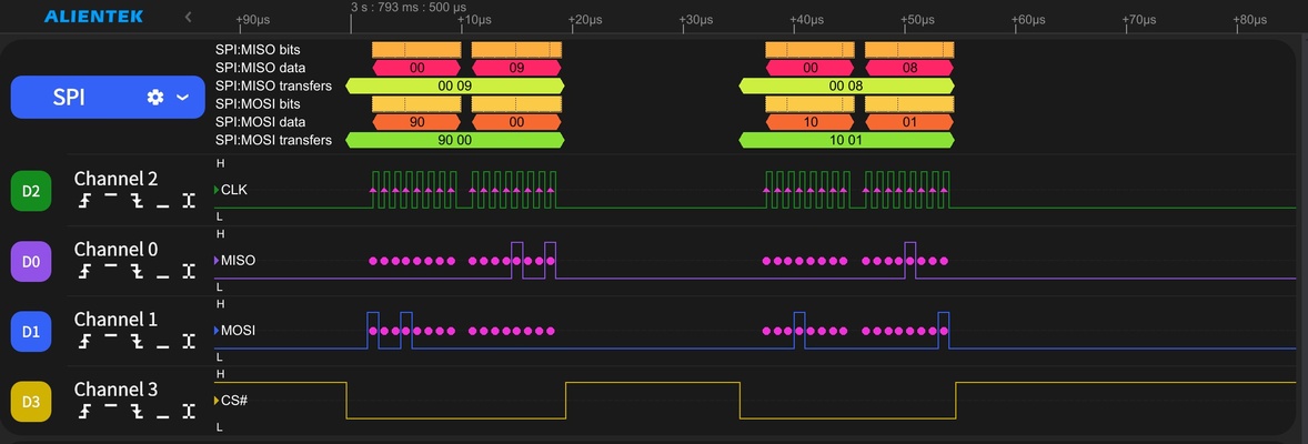
SPI: the WROOM drives the ST7789 display with a clock plus MOSI/MISO and chip-select style
control pins. SPI is fast and good for pixels, but it does not provide a shared bus address like I²C; the
selected display is chosen by
CSand command/data pins.
2. Learning
Group BLE and logic-analyzer I²C work reminded me that “communication” is two problems:
link state, and the bytes on the wire. On my plant stack I spelled out the wired version.
UART is asynchronous (baud and framing, no shared clock). I²C is synchronous on
SDA/SCL with a 7-bit address. Pico and WROOM stay on separate boards so the
NanoStat analog front-end does not share pins with TFT SPI; between them I only pass a small
HostLink protocol.
On the Pico → XIAO hop, Pico prints
STAT,ver=1,valid=…,level=…,nidx=…,dz10k=…,reason=… lines about every
2.5 s. XIAO’s PicoStatBridge parses those fields, packs an 8-byte binary
frame, and keeps parsing out of ISR context, same idea as Week 10’s I²C slave ring
buffer. On the XIAO → WROOM hop I reused HostLink from Week 10:
TelemetryPacked (magic 0xA5, cmd 0x01) for
environment, plus PlantStatusPacked (cmd 0x07) for level, N-index,
and flags (valid / stale / contact / range / repeat).
I did not move Pico → XIAO to I²C. The NanoStat stack already speaks UART in its vendor workflow, and I did not want impedance samples on a shared bus next to DHT timing. Revision 2 of my carrier ( Week 6) routed NanoStat’s six programming pads, including two UART lines, toward the ESP32‑S3 hub so a future spin can solder this hop instead of rainbow wire.
3. Plan
-
Stage 1: UART only: Flash Pico
phase1_uart_statand XIAOpico_uart_echo; confirmSTAT,…on Pico USB and matching lines on XIAO USB (D7 ← Pico TX). -
Stage 2: I²C plant frame: XIAO
pico_plant_hostlinkpushes0x07to WROOM; WROOM shows Plant info bars without environment merge. -
Stage 3: Full hub:
S3上传程序+PICO上传程序+WROOM上传程序, with environment0x01and plant0x07in parallel. -
Evidence: boot I²C scan lists
0x55; serial banners[PICO UART]/[PLANT TX] ok; TFT Environment + Plant info pages live; bench photos and USB serial captures in §4 (UART + I²C hops).
4. Build and wiring
Hop 1: UART (Pico → XIAO)
| Signal | Pico (NanoStat) | XIAO ESP32‑S3 |
|---|---|---|
| TX → RX | GPIO1 (UART TX) | D7 → GPIO44 (UART2 RX) |
| Ground | Common GND (required) | |
| Baud | 115200 8N1 | |
XIAO does not need Pico’s RX for this chain. Receive-only is enough. I power each board from its own USB during bring-up so a ground fault on one supply does not drag the other into brown-out; only signal + GND cross the harness.
Example line from Pico (documented in PICO上传程序/README.md):
STAT,ver=1,valid=1,level=2,nidx=58,zl=...,zm=...,zh=...,dz10k=0.240,reason=ok,ts=123456
XIAO maps that into HostLink PlantStatusPacked: level 0–3,
nidx 0–100, dz_x100 from dz10k, and flags derived from
valid and reason (ok, debounce, contact,
range, repeat, …). If UART goes quiet for 10 s, the bridge clears
kPlantFlagValid and sets kPlantFlagStale so the UI does not show frozen plant data.
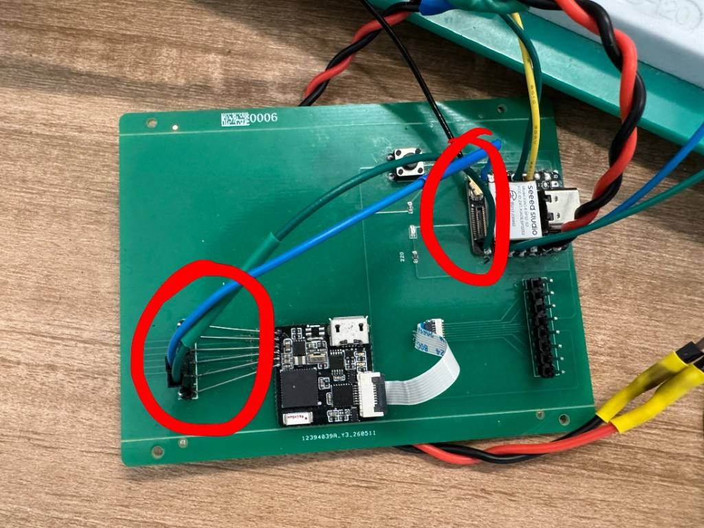
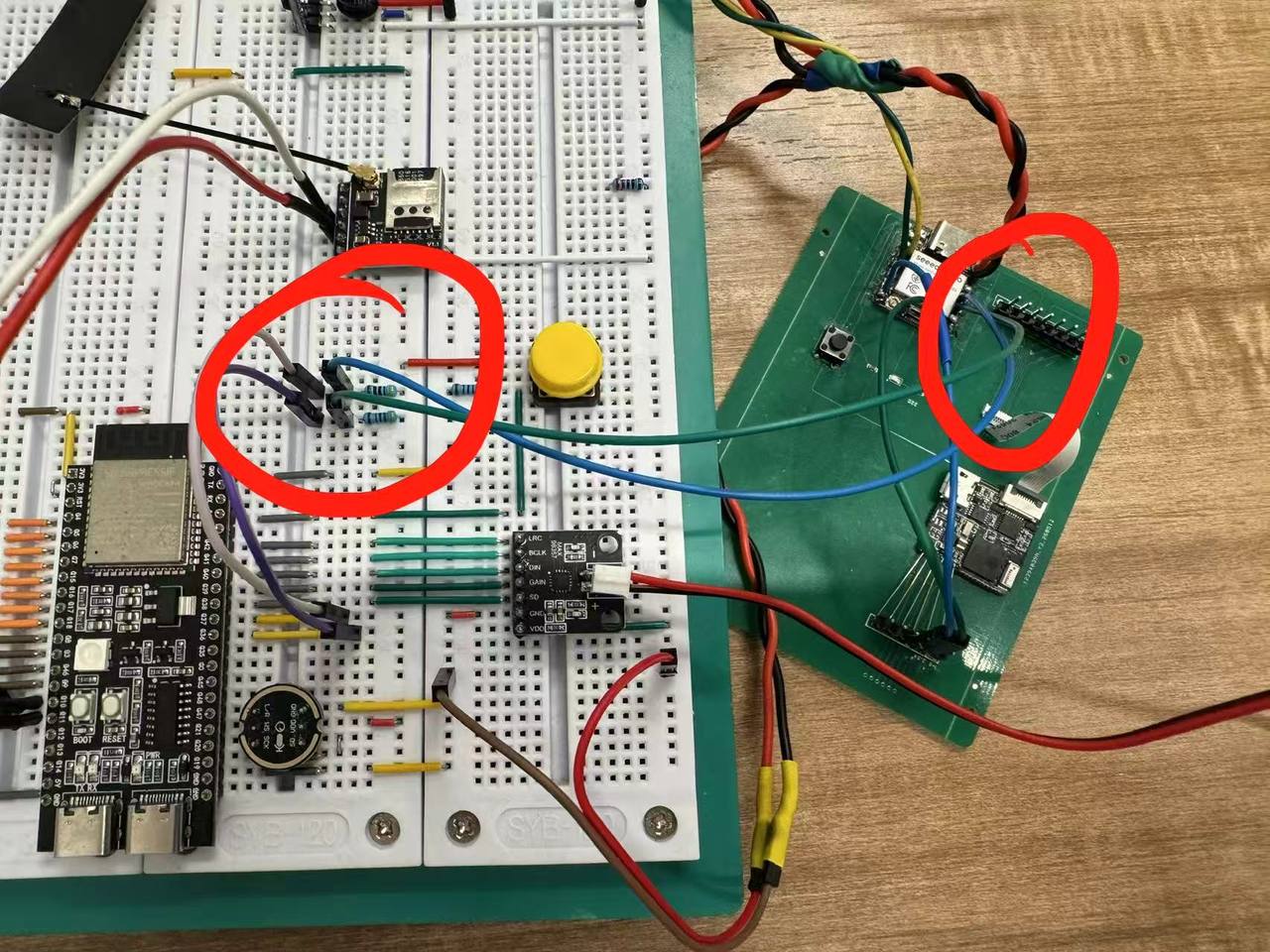
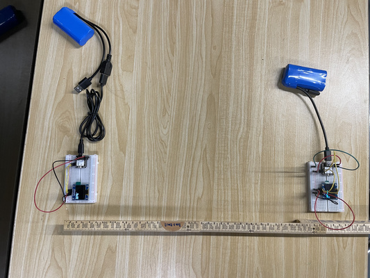
STAT,… on TX; the blue/green pair lands on XIAO
D7 (GPIO44, RX) with common ground on the carrier. Red circles mark the splice I
probed while bringing up pico_uart_echo.
Hop 2: I²C (XIAO → WROOM)
Unchanged from Week 10: XIAO D4/D5 (GPIO9/8) → WROOM GPIO37/36, 4.7 kΩ pull-ups to 3.3 V, slave 0x55, 100 kHz. Week 11 adds a second periodic write for plant status without changing the environment frame layout.
0x01) and Plant info (0x07) once both
hops are alive.
Firmware in the repo
Documented in
code/week11-network/README.md
(trimmed from Downloads PICO上传程序, S3上传程序,
WROOM上传程序):
-
Pico (UART out):
week11-network/pico/, LMP91000 measure, printSTAT,…@ 115200. -
XIAO hub:
week11-network/xiao/, DHT/light →0x01;pico_stat_bridge.cppparses UART →0x07. -
WROOM display:
week11-network/wroom/,env_i2c_slave.cpp+ ST7789 Plant / Environment pages. -
Shared protocol:
i2c_env_link.h(TelemetryPacked,PlantStatusPacked).
// XIAO — after parsing STAT,… (see pico_stat_bridge.cpp)
Wire.beginTransmission(0x55);
Wire.write((uint8_t*)&plantPkt, sizeof(plantPkt));  // cmd 0x07
Wire.endTransmission();
Bring-up checklist (from product README)
- Pico USB: continuous
STAT,…withvalidfield every line. - Disconnect electrodes: expect
valid=0,reason=rangeorcontact. - XIAO USB:
[I2C SCAN]shows 0x55 when WROOM is powered. - With Pico running:
[PICO UART]parse logs and periodic[PLANT TX] ok. - WROOM TFT: swipe to Plant info — N bar and level track Pico; Environment still updates
from hub
0x01.
Serial monitor: both hops working
After the harness matched the tables above, I used two USB serial ports to close the loop:
Pico USB for outgoing STAT,… lines and XIAO USB for bridge logs that show parsing
and I²C writes. The screenshots are my check record for Fab’s “links work” requirement.
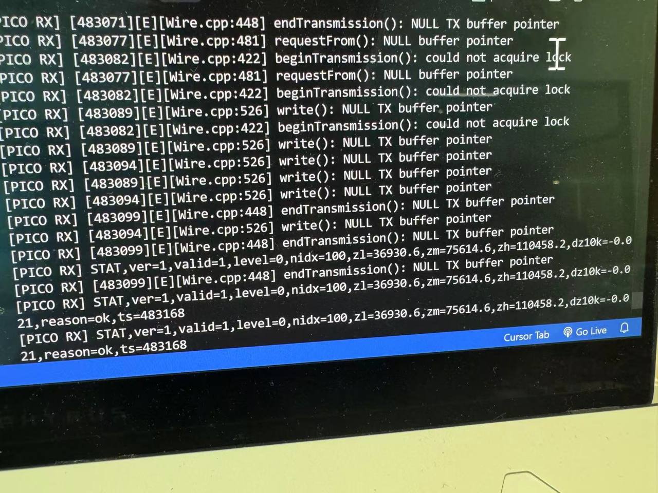
STAT,ver=1,valid=1,…,reason=ok lines from Pico (prefix
[PICO RX] in this bench build). Earlier Wire lock errors were from bring-up
order; once Pico TX and XIAO D7 shared ground, the parser saw steady reason=ok traffic.
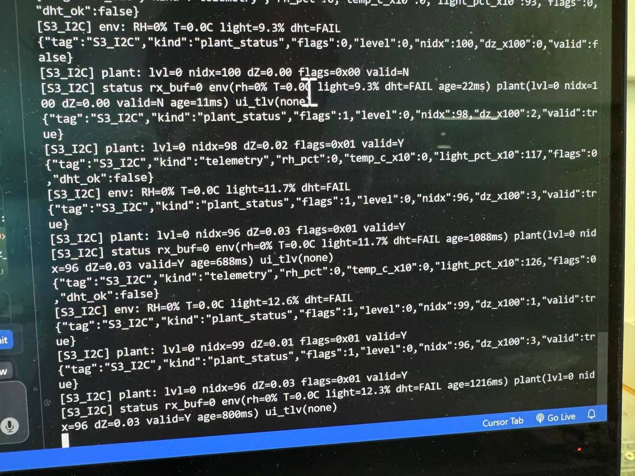
[S3_I2C] plant_status (cmd 0x07) and
telemetry (cmd 0x01) frames with valid:true and live light
percentages, so the master reached WROOM at 0x55 while environment and plant channels
run in parallel.
Problems I watch for
-
Garbled UART: TX/RX swapped or missing GND. Parser never sees complete
STAT,…lines; fix harness before touching I²C. - No 0x55 on scan: same pull-up / power issues as Week 10. Plant bridge cannot display even if UART is perfect.
- Stale plant UI: intentional after 10 s UART silence. Check Pico reset or loose D7 wire, not WROOM graphics code first.
-
Group lesson carry-over: noisy logic-analyzer traces still decode if address
(
0x55/0x3Con lab OLEDs) matches. I apply that patience to HostLink debug.
5. Conclusion
I used Cursor to code the three-role network stack in
code/week11-network/ — Pico UART bridge, XIAO HostLink master, and
WROOM TFT receiver. I still traced each bus with a logic analyzer and fixed flag packing in telemetry before the
Environment and Plant pages showed trustworthy numbers.
Week 11 closes the loop I sketched on paper: Pico sends plant stats over UART, the
Week 8 XIAO hub wraps HostLink frames at 0x55, and the WROOM TFT shows
Environment and Plant info. Same three-role split as the final project, now with two buses I
can re-test from saved firmware in
code/week11-network/.
Design files:
Week 6 electronics ·
Week 8 production.
Prior serial / I²C:
Week 9 inputs ·
Week 10 HostLink 0x01.
Week 11 firmware:
code/week11-network/.
Full product trees: Downloads PICO上传程序,
S3上传程序, WROOM上传程序.
Group reflection:
BLE + I²C captures below.
Group assignment
Fab asked us to verify direct wired or wireless communication between two nodes and document setup, behavior, and signals. We did BLE between two ESP32C3 XIAO boards and I²C on the OLED path with a logic analyzer.
What we built
We ran a two-node test with two XIAO ESP32C3 boards: one BLE server, one client, both driving OLEDs so scan/connect/retry states were visible without staring at serial. On the wired side we probed I²C between a XIAO and its OLED with a logic analyzer while the client kept updating the screen.
I came in thinking “networking” meant picking UART vs I²C vs BLE on paper. After a disconnect
at range and a noisy analyzer trace that still showed 0x3C writes, I stopped treating
networking as one problem. Link state, retry logic, and bus bytes all need separate checks.
Hardware and protocol notes
Gear: two XIAO ESP32C3 boards, I²C OLED modules at 0x3C, an IPEX antenna for
range comparison, a logic analyzer, and breadboard jumpers. On BLE the server advertises a
service; the client scans and connects. On I²C, SDA carries data and
SCL carries clock, with ACK/NACK marking each byte. A single-board demo hides
timeout and reconnect bugs; two nodes expose them quickly.
Week 11 covers wired and wireless links. Splitting a project across boards only works if each
hop has an address, a defined frame, and a way to detect a dead link. Our BLE range test and
my later UART stale flag on the plant hub handle the same kind of failure. UART is
async serial with no shared clock. I²C is synchronous on SDA/SCL with multiple
addressed devices. SPI is synchronous full duplex with separate data, clock, and chip-select
lines. BLE is short-range wireless between nodes. We exercised BLE for the wireless hop and
I²C on the OLED wired to each ESP32C3.
BLE two-node test
The server continuously advertised a fixed BLE service UUID. The client
scanned for the target device name thexiao, locked onto the
device, and initiated connection when found. OLED screens were used
to show states such as scanning, connected, and retrying after disconnect.
During the distance test, we also observed that the connection could drop beyond a certain range and then recover after the client resumed scanning and reconnected.
BLE implementation notes
Each node consisted of a XIAO ESP32C3 plus an OLED display. One node
acted as the BLE server and advertised its presence. The other acted
as the client, scanning nearby devices and connecting to the server
when the device name thexiao was found.
Because the XIAO ESP32C3 code uses BLE library objects,
pointer syntax appears often in the sketch. For example,
BLEServer* pServer; means pServer stores the
memory address of a BLE server object, and -> is used
to access methods on that object.
BLEServer* pServer;
pServer = BLEDevice::createServer();
pServer->createService(SERVICE_UUID);
Server code excerpt
The server waits for a client connection, updates the OLED through BLE callbacks, and restarts advertising after disconnect.
#include <BLEDevice.h>
#include <BLEServer.h>
#include <BLEUtils.h>
#include <Wire.h>
#include <Adafruit_GFX.h>
#include <Adafruit_SSD1306.h>

#define SCREEN_WIDTH 128
#define SCREEN_HEIGHT 64
#define OLED_RESET -1
#define OLED_ADDRESS 0x3C
#define PIN_SDA 6
#define PIN_SCL 7

#define SERVICE_UUID        "4fafc201-1fb5-459e-8fcc-c5c9c331914b"
#define CHARACTERISTIC_UUID "beb5483e-36e1-4688-b7f5-ea07361b26a8"
#define DEVICE_NAME         "thexiao"

Adafruit_SSD1306 display(SCREEN_WIDTH, SCREEN_HEIGHT, &Wire, OLED_RESET);

BLEServer* pServer;
BLECharacteristic* pCharacteristic;

bool deviceConnected = false;
bool lastState = false;

void oledShow(const char* a, const char* b, const char* c, const char* d) {
    display.clearDisplay();
    display.setTextSize(1);
    display.setTextColor(SSD1306_WHITE);
    display.setCursor(0, 0);
    display.println(a);
    display.println(b);
    display.println(c);
    display.println(d);
    display.display();
}

class ServerCallbacks : public BLEServerCallbacks {
    void onConnect(BLEServer* server) override {
        deviceConnected = true;
    }

    void onDisconnect(BLEServer* server) override {
        deviceConnected = false;
        delay(100);
        pServer->getAdvertising()->start();
    }
};
Client code excerpt
The client continuously scans for the target server, connects when found, reads the characteristic value, and restarts scanning after disconnect.
#include <BLEDevice.h>
#include <BLEUtils.h>
#include <BLEScan.h>
#include <BLEAdvertisedDevice.h>
#include <BLEClient.h>
#include <Wire.h>
#include <Adafruit_GFX.h>
#include <Adafruit_SSD1306.h>

#define SERVICE_UUID "4fafc201-1fb5-459e-8fcc-c5c9c331914b"
#define CHARACTERISTIC_UUID "beb5483e-36e1-4688-b7f5-ea07361b26a8"
#define DEVICE_NAME_TARGET "thexiao"

BLEScan *pBLEScan = nullptr;
BLEClient *pClient = nullptr;
volatile bool wantConnect = false;
volatile bool connected = false;
BLEAddress *pTargetAddr = nullptr;

class ScanCallbacks : public BLEAdvertisedDeviceCallbacks {
void onResult(BLEAdvertisedDevice advertisedDevice) {
    if (connected || wantConnect) return;
    if (!advertisedDevice.haveName()) return;
    if (advertisedDevice.getName() != DEVICE_NAME_TARGET) return;

    if (pBLEScan) pBLEScan->stop();
    pTargetAddr = new BLEAddress(advertisedDevice.getAddress());
    wantConnect = true;
}
};

void loop() {
if (wantConnect && !connected && pTargetAddr != nullptr) {
    if (pClient->connect(*pTargetAddr)) {
        wantConnect = false;
    }
}
delay(50);
}
The full sketches also included OLED status updates, reconnect logic, and characteristic reads, so we could debug the experiment in real time.
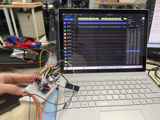
I2C signal observation
We used a logic analyzer on the I²C line between the XIAO ESP32C3 and the OLED while the
client was running. The capture was messy, but after a few minutes with the decode table I
could still pick out OLED address 0x3C, write bytes, and ACKs. Noise showed up,
yet enough of the transaction looked like a normal SSD1306 update that we called the wired
path working.
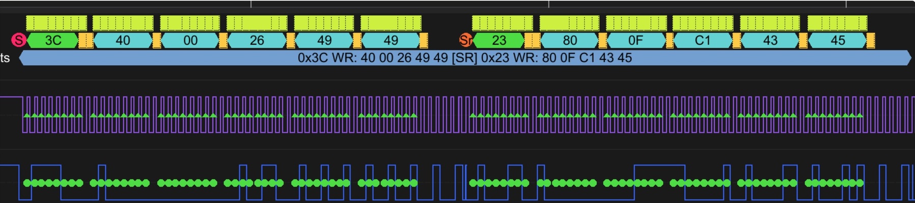
I2C packet interpretation
Since the BLE client kept scanning and updating the OLED, the logic analyzer captured frequent I2C activity. Two packets were identified during inspection.
| Packet | Observed bytes | Interpretation |
|---|---|---|
| Packet 1 | 0x3C WR, 0x40, 0x00, 0x26, 0x49, 0x49 |
Expected OLED write transaction with valid display data bytes. |
| Packet 2 | 0x23 WR, 0x80, 0x0F, 0xC1, 0x43, 0x45 |
Likely noise or an unintended decode, because that device was not part of the setup. |
The first packet matched the intended OLED address 0x3C
and behaved like a normal write transaction. Even though the second
operation appeared noisy, the expected first packet and visible ACK
responses indicated that the I2C communication itself was still working.
Binary to hexadecimal example
To interpret logic-analyzer output more confidently, we also reviewed a basic binary-to-hexadecimal conversion example:
Binary: 01001001
Split into 4-bit groups: 0100 1001
0100 = 4
1001 = 9
Hexadecimal = 0x49
That conversion maps analyzer bytes like 0x49 back to the binary bit patterns in the OLED stream.
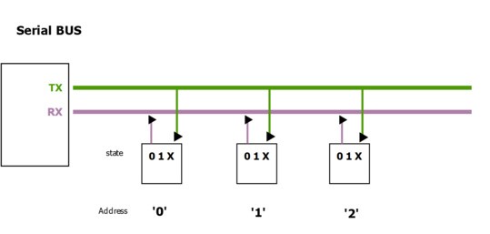
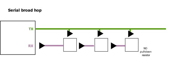
Topology reference diagrams

Code summary
Server advertises a service, updates the OLED on connect/disconnect, and restarts advertising
after a drop. Client scans for thexiao, connects, reads the characteristic, then
scans again after loss. Both sketches mirror state on the OLED so we could film the lifecycle
without a laptop in frame.
Results
BLE server and client ran on two ESP32C3 boards; the range test dropped the link and
recovered after the client scanned again. OLED text tracked scanning, connected, and retry
during that walk. On I²C we decoded expected 0x3C writes plus one stray packet
we flagged as noise. The packet table and binary-to-hex example are in the write-up so the
photos are not the only record.