Week 11 : Networking & Communications
PCB CNC milling not available at time of writing at the workspace. Thus, tests were mainly done on breadboard. The final result-with the CNC milling- could be seen further below
Networking refers to the connection of multiple devices that enables communication and the exchange of data between them. This approach offers several advantages as it enables modularity:
- Reduce interference of signals i.e. separating voltage and signal buses
- Allowing individual parts of a system to be developed, tested, and replaced
Week 11 assignment could be categorized as follows:
- Group assignment
- Direct wired/wireless communication between two nodes
- Individual assignment
- Wired/wireless integration (to designed embedded microcontroller system)
Additional details beyond those presented in this document can be found in the Chaihuo's 2026 Week 11 group documentation.
Basics of hardware communications
Hardware communication can be categorized into wired and wireless methods.
-
Wired
-
Communication method (how bits are transmitted):
- Peripherals
- PIO : Programmable processor inside (certain) microcontrollers for custom I/O behavior (e.g. want more than one I2C/SPI bus)
- GPIO : Basic digital pins. Can be used for bit-banging (method of sending and receiving data manually through software and the GPIOs instead of using dedicated hardware peripheral and so could behave like the PIO)
- Hardware specific peripherals :
- UART/USART
- I2C
- SPI
-
Asynchronous serial communication (UART)
- No shared clock signal between devices. Instead both sides must agree in advance on parameters such as the baud rate (number of bits transmitted per second). 9600 baud means each bit takes approximately 1 / 9600 ≈ 0.000104 sec (104 µs) to transmit.
- Standards :
- RS - 232 : Older standard using higher voltage levels (12 V)
- RS - 485 : Used in industry
- Communication schemes for multiple devices (methods or rules that define how devices exchange data on a network):
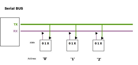
- Serial broadcast : sending a message to all nodes on a network/bus. The master sends command through TX and all microcontrollers for example receive it on RX. IDs are assigned to devices so that it is clear if the message is meant for them or not.
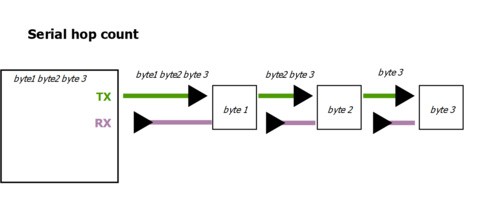
- Hop-count : sending message based on the number of devices that it has passed through. First device for example sends a message with hop = 0. Each device then incremenents the hop count as it forwardes the message. Advantage of this method is that no device IDs or address is needed (e.g. LED strips).
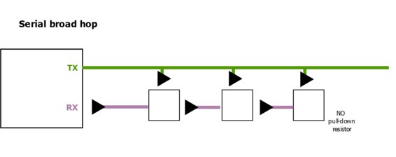
- Broad-hop : Combination of serial broadcast and hop-count. Each devices could activate immediately and at the same time no device IDs or address is needed.
- Serial broadcast : sending a message to all nodes on a network/bus. The master sends command through TX and all microcontrollers for example receive it on RX. IDs are assigned to devices so that it is clear if the message is meant for them or not.
-
Synchronous serial communication
- Receiver/slave and sender/master is used interchangeably.
- Shared clock signal between devices. Master control the pulses/timing of the connected devices.
- Types :
- I2C/TWI :
- Variations : QWIC from SparkFun, STEMMA (Adafruit)
- Uses two lines :
- SDA (serial data Line) : Carries data
- SCL (serial clock line)
- Implication : Data can go both direction, but only one direction at a time
- Communication steps :
- Start. Master initiates communication. SDA low. SCL high (high always mean that device should read, low means reject).
- Master sends 7-bit address of the slave (i.e. select which device) and the R/W (read or write) bit. This is required because data can only go one direction at a time
- At the 9th bit, the slave/received responds with ACK (i.e. acknowledged) or NACK (i.e. not acknowledged) and is represented by SDA low and SDA high respectively
- Stop. SDA high. SCL high.
- SPI :
- Uses four lines :
- MOSI (master out, slave in) : Carries data from master to slave
- MISO (master in, slave out) : Carries data from slave to master
- CS (chip select) : slave select i.e. activates a specific slave device
- SCK : serial clock
- Implication : Data can go both direction and at the same time
- Communication steps :
- Master selects slave. CS low
- MOSI and MISO can run at the same time, and so the equivalent of ACK at I2C is simply the response from example the MISO
- Stop signal. CS high
- Uses four lines :
- I2C/TWI :
- Communication protocol (rules, structure and system behaviour. Built on top of communication method):
- USB :
- Human interface device (HID) : keyboard, mouse, game controller, etc
- Musical instrument digital interface (MIDI) : synthesizers, drumpads. Instead of raw data, it sends musical messages or instructions to create sound(Note ON, note OFF, velocity or how hard the button is pressed, control changes such as knobs and sliders)
- Ethernet : widely used for local area networks (LANs). Operates at the layer 2 of the OSI (i.e. MAC) model
- Note : Use the modules, not the chips.
- CAN/LIN : Industrial application
- MODBUS : Industrial application
- DMX : Commonly used for street lighting systems
- USB :
- Peripherals
-
7 layers of networking :
This table maps the 7 OSI layers to embedded networking technologies, with the role descriptions included inline.
| OSI Layer | Role | Embedded / Networking Examples |
|---|---|---|
| 7. Application | User-level protocol; what the device/application actually uses | HTTP (web, runs with TCP), MODBUS TCP, MQTT (usually for IoT and low power devices), USB HID/MIDI, REST API |
| 6. Presentation | Handles encryption, compression, and data representation | SSL/TLS (HTTPS), JSON / XML, MIDI packet formatting |
| 5. Session | Keeps track of ongoing conversations between devices | TCP sessions, MQTT persistent sessions, WebSocket sessions (i.e. browser and app communication) |
| 4. Transport | Ensures data is delivered correctly and in order; manages ports (tells OS which application/service should handle incoming or outgoing network traffic. Without port numbers, computer will not know whether incoming data is meant for browser, email, or some other app, because all share the same IP address). | TCP (client establishes a connection with server, data is sent in packets and each packet is acknowledged, lost packets are retransmitted), UDP (client sends packets to server no ACK, server receives what it can and missing packets are ignored); Modbus TCP; socket = combination of IP + port + transport protocol (endpoint communication between machines). Analogy: user's apartment number |
| 3. Network | Determines how data reaches the correct device across networks | the correct device across networks IPv4/IPv6 (e.g. 192.168.1.1), DNS (human-readable IP names, e.g. www.tim.com), routing tables, Zigbee network addresses. Analogy: street address of the apartment |
| 2. Data Link / MAC | Prevents collisions, wraps data in frames, decides who talks when, unique identifier assigned to a network chip. Analogy is the apartment door name at the mailbox | Ethernet MAC addresses, I²C/SPI master-slave rules, Wi-Fi CSMA/CA (listen first, transmit if idle; if busy, wait random time). Analogy: apartment door/mailbox name |
| 1. Physical | The hardware layer; bits moving over wires or wireless signals | Ethernet cables, fiber optics, SPI/I²C/UART signals, Wi-Fi radio |
- Lower layers (1–2) → mostly handled by hardware (SPI, I²C, Ethernet, CAN controller)
- Middle layers (3–4) → handled by hardware + software stacks (IP stack, TCP/UDP stack). Stacks here is defined as collection of software components that works together to implement a certain functionality.
- Upper layers (5–7) → handled in firmware or application code (HTTP, MQTT, USB HID/MIDI)
-
Note :
- Fabacademy generally focuses on layer 1 to 3
- Virtual private network (VPN) :
- Creates a secure, encrypted tunnel over the public Internet
- Internet service providers may intentionally slow down specific traffic (throttling) and so with VPN it could be faster
- Steps :
- Your device sends data → VPN software encrypts it
- Encrypted data is sent through the Internet to a VPN server
- VPN server decrypts the data
- VPN server forwards the request to the destination server (e.g. website)
- Response comes back → VPN server encrypts it again
- Your device receives and decrypts it
-
Wireless :
- Frequency
- Higher frequency, shorter wavelength. Carry more data but absorbed or reflected by obsatcles more easily (e.g. 2.4 GHz Wi-Fi), could be even just line of sight.
- Lower frequency, longer wavelength. Carry less data, but travels farther and through walls (e.g. 433 MHz LoRa)
- Capacity
- Amount of data that a channel can carry reliably. Measured in bits per second (bps or Mbps).
- Bandwidth : Range of frequencies a channel can use to transmit data. Measured in Hz. Higher
- Signal-to-noise ratio (SNR) : Strength of desired signal vs background noise. Measured in dB.
- High capacity = High bandwidth, high SNR
- Note : In the ocean not much interference
- Band : Range of radio frequencies grouped together for a specific type of communication. Example 2.400-2.4835 is equals to 2.4 GHz ISM band
- Industrial, scientific, medical (ISM) bands are frequency ranges reserved for unlicensed used. Meaning anyone can use it without special government license.
- IEEE standards for wireless communication :
-
Network model :
- Client - server : device request data (client) or a device hosts data (server). Requires access points (AP) like Wi-Fi routers that manages wireless clients to connect to a network (e.g. converts digital data to radio waves at physical layer, then manages MAC addresses, prevents collissions, schedules timing of the communication between clients at the data link layer). Example: An ESP32 Wi-Fi module requests the current time from a server on the Internet. The request goes through a Wi-Fi router (AP), which forwards the data and sends back the response.
- Mesh networking :Devices (nodes) communicate directly with each other without requiring a central AP. Data can hop through multiple intermediate nodes to reach its destination. Some nodes, called meshcore, manage routing and may connect the mesh to the Internet (e.g. Raspberry pi), while meshtatic or edge nodes relay data and perform sensing or actuation.
-
Technology :
Technology Type Range Frequency Data Rate Power Usage Internet Support Wi-Fi RF 50–100 m 2.4 / 5 GHz 10–600 Mbps 100–1000 mW Yes Bluetooth (BLE) RF 10–50 m 2.4 GHz 125 kbps–2 Mbps 1–10 mW Indirect (via phone/gateway) RFID / NFC RF 0.04–0.1 m 13.56 MHz / 125–134 kHz 106–424 kbps ~0 mW (passive) No LoRa RF 2–15 km 433 / 868 / 915 MHz 0.3–50 kbps 10–100 mW No (requires LoRaWAN) Optical (IR) Light 1–10 m 400–800 THz 10–100 kbps 10–50 mW No -
Radio Frequency (RF)
-
Wi-Fi
- Requires access point (router)
- Wireless local network (also LAN, see ethernet). Internet comes from the internet service provider and router/access point acts as a gateway between the two.
-
Bluetooth :
- Bluetooth Low Energy (BLE) is a subset. nRF Toolbox by Nordic can be used for testing and communication
- Radio Frequency Identification (RFID):
- Near Field Communication (NFC) is a subset. No battery required. Harvest energy from the reader's electromagnetic field.
- LoRA (Long Range)
- LoRAWAN is a network protocol built on LoRA. Can be deployed as private or public networks
-
-
Optical (Light-based communication). Higher frequency than RF
- Uses infrared or visible light
- No licensing
-
- Frequency
Source: ChatGPT by OpenAI, April 2026
Direct wired/wireless communication between two nodes
In previous weeks, wired communication has already been explored multiple times. Therefore, the experiment this time primarily focuses on testing wireless communication between nodes. The XIAO ESP32C3 supports Bluetooth Low Energy (BLE), and so its functionality is tested to evaluate its usability and communication range.
The I2C communication with the microcontroller will be further investigated - building on the work from week 6 : Electronics design - using a logic analyzer to better understand and decode the data.
Bluetooth communication (2x XIAO ESP32C3)
A node consist of a XIAO ESP32C3 and is connected to an OLED display to show the status of the connection (i.e. connected or disconnected). The task of the corresponding nodes are as follows :
- One acts as the server, advertising its presence and responding to data requests through services. Characteristics are individual pieces of information within those services, which clients can read or write.
- One acts as the client. Scans nearby BLE devices and connects to the server.
It could be seen that the two devices could disconnect if a certain distance threshold is passed.
The code used for this experiment is primarily based on the official Seeed Studio example for BLE communication on the XIAO ESP32C3. It is adapted to fit the experiment setup and the code could be seen at the admonitions below. Since it works with the "pointers" concept, some explanations are also given below.
Basic info about pointers/scope resolution operator
A pointer is a variable that does not store a value directly, but instead stores the memory address of another variable or object. An example is given below :
Where :
BLEServera blueprint for a BLE server object. Essential to be called.*is a pointer (stores the address of a BLEServer object)pServeris variable name. Can also be other name->is a function that basically request the variable to access the address and use the function of the object::uses the original function of an object by the developer
Source: ChatGPT by OpenAI, April 2026
Server OLED x XIAO ESP32C3 BLE code
Server waits for client to connect, reacts through callbacks and updates the OLED respectively, and can notify client of any changes in the characteristic value.
For more details on the code i.e. programming language, please refer to resources online.
#include <BLEDevice.h>
#include <BLEServer.h>
#include <BLEUtils.h>
#include <Wire.h>
#include <Adafruit_GFX.h>
#include <Adafruit_SSD1306.h>

// ----- OLED (128x64 I2C) -----
#define SCREEN_WIDTH 128
#define SCREEN_HEIGHT 64
#define OLED_RESET -1
#define OLED_ADDRESS 0x3C
#define PIN_SDA 6
#define PIN_SCL 7

// ----- BLE UUIDs -----
#define SERVICE_UUID        "4fafc201-1fb5-459e-8fcc-c5c9c331914b"
#define CHARACTERISTIC_UUID "beb5483e-36e1-4688-b7f5-ea07361b26a8"
#define DEVICE_NAME         "thexiao"

Adafruit_SSD1306 display(SCREEN_WIDTH, SCREEN_HEIGHT, &Wire, OLED_RESET);

BLEServer* pServer;
BLECharacteristic* pCharacteristic;

bool deviceConnected = false;
bool lastState = false; // track OLED updates

// OLED helper
void oledShow(const char* a, const char* b, const char* c, const char* d) {
    display.clearDisplay();
    display.setTextSize(1);
    display.setTextColor(SSD1306_WHITE);
    display.setCursor(0, 0);
    display.println(a);
    display.println(b);
    display.println(c);
    display.println(d);
    display.display();
}

// BLE callbacks
class ServerCallbacks : public BLEServerCallbacks {
    void onConnect(BLEServer* server) override {
        deviceConnected = true;
        Serial.println("Device Connected");
    }

    void onDisconnect(BLEServer* server) override {
        deviceConnected = false;
        Serial.println("Device Disconnected");

        // Restart advertising
        delay(100);
        pServer->getAdvertising()->start();
        Serial.println("Advertising restarted");
    }
};

void setup() {
    Serial.begin(115200);

    // Initialize OLED
    Wire.begin(PIN_SDA, PIN_SCL);
    if (!display.begin(SSD1306_SWITCHCAPVCC, OLED_ADDRESS)) {
        Serial.println(F("SSD1306 begin failed"));
        while (true) delay(1000);
    }
    oledShow("thexiao", "booting...", "", "");

    // BLE init
    BLEDevice::init(DEVICE_NAME);
    pServer = BLEDevice::createServer();
    pServer->setCallbacks(new ServerCallbacks());

    BLEService* pService = pServer->createService(SERVICE_UUID);

    // BLE characteristic with READ, WRITE, NOTIFY
    pCharacteristic = pService->createCharacteristic(
        CHARACTERISTIC_UUID,
        BLECharacteristic::PROPERTY_READ |
        BLECharacteristic::PROPERTY_WRITE |
        BLECharacteristic::PROPERTY_NOTIFY
    );

    pCharacteristic->setValue("you found me!!");
    pCharacteristic->addDescriptor(new BLE2902()); // required for NOTIFY

    pService->start();

    // Start advertising
    BLEAdvertising* adv = BLEDevice::getAdvertising();
    adv->addServiceUUID(SERVICE_UUID);
    adv->setScanResponse(true);
    BLEDevice::startAdvertising();

    oledShow("thexiao", "hiding in RF", "find me...", "");
}

void loop() {
    // Only update OLED when connection state changes
    if (deviceConnected != lastState) {
        lastState = deviceConnected;

        if (deviceConnected) {
            oledShow("YOU FOUND ME", "ok u win", "hello!", "");
        } else {
            oledShow("thexiao", "still hiding", "...", "...");
        }
    }
    delay(100);
}
Client OLED x XIAO ESP32C3 BLE code
Client seeks the server, connects when found, reads data and shows status on OLED, and keeps trying if disconnected
For more details on the code i.e. programming language, please refer to resources online.
#include <BLEDevice.h>
#include <BLEUtils.h>
#include <BLEScan.h>
#include <BLEAdvertisedDevice.h>
#include <BLEClient.h>
#include <Wire.h>
#include <Adafruit_GFX.h>
#include <Adafruit_SSD1306.h>

#define SCREEN_WIDTH 128
#define SCREEN_HEIGHT 64
#define OLED_RESET -1
#define OLED_ADDRESS 0x3C
#define PIN_SDA 6
#define PIN_SCL 7

#define SERVICE_UUID "4fafc201-1fb5-459e-8fcc-c5c9c331914b"
#define CHARACTERISTIC_UUID "beb5483e-36e1-4688-b7f5-ea07361b26a8"

#define DEVICE_NAME_TARGET "thexiao"

Adafruit_SSD1306 display(SCREEN_WIDTH, SCREEN_HEIGHT, &Wire, OLED_RESET);

BLEScan *pBLEScan = nullptr;
BLEClient *pClient = nullptr;

volatile bool wantConnect = false;
volatile bool connected = false;
BLEAddress *pTargetAddr = nullptr;

// Store last seen device info
String lastName = "";
int lastRSSI = 0;

// OLED helper
void oledShow(String a, String b, String c, String d) {
display.clearDisplay();
display.setTextSize(1);
display.setTextColor(SSD1306_WHITE);
display.setCursor(0, 0);
display.println(a);
display.println(b);
display.println(c);
display.println(d);
display.display();
}

// Client callbacks
class ClientCallbacks : public BLEClientCallbacks {
void onConnect(BLEClient *c) {
    connected = true;
}

void onDisconnect(BLEClient *c) {
    connected = false;
    wantConnect = false;

    if (pTargetAddr) {
    delete pTargetAddr;
    pTargetAddr = nullptr;
    }

    if (pBLEScan) {
    pBLEScan->clearResults();
    pBLEScan->start(0, false);
    }
}
};

// Scan callbacks
class ScanCallbacks : public BLEAdvertisedDeviceCallbacks {
void onResult(BLEAdvertisedDevice advertisedDevice) {

    // Save last seen device for display
    if (advertisedDevice.haveName()) {
    lastName = advertisedDevice.getName();
    } else {
    lastName = "(no name)";
    }
    lastRSSI = advertisedDevice.getRSSI();

    // Show scanning activity on OLED
    if (!connected && !wantConnect) {
    oledShow("Scanning...",
            lastName,
            "RSSI: " + String(lastRSSI),
            "");
    }

    // Check for target
    if (connected || wantConnect) return;
    if (!advertisedDevice.haveName()) return;

    if (advertisedDevice.getName() != DEVICE_NAME_TARGET) return;

    // FOUND TARGET
    if (pBLEScan) pBLEScan->stop();

    if (pTargetAddr) {
    delete pTargetAddr;
    pTargetAddr = nullptr;
    }

    pTargetAddr = new BLEAddress(advertisedDevice.getAddress());
    wantConnect = true;
}
};

void setup() {
Serial.begin(115200);
Wire.begin(PIN_SDA, PIN_SCL);

if (!display.begin(SSD1306_SWITCHCAPVCC, OLED_ADDRESS)) {
    Serial.println(F("SSD1306 begin failed"));
    while (true) delay(1000);
}

oledShow("seeker mode", "scanning...", "", "");

BLEDevice::init("");

pClient = BLEDevice::createClient();
pClient->setClientCallbacks(new ClientCallbacks());

pBLEScan = BLEDevice::getScan();
pBLEScan->setAdvertisedDeviceCallbacks(new ScanCallbacks());
pBLEScan->setActiveScan(true);
pBLEScan->setInterval(500);
pBLEScan->setWindow(49);

pBLEScan->start(0, false);
}

void loop() {
static unsigned long lastScanRestart = 0;

if (wantConnect && !connected && pTargetAddr != nullptr) {
    oledShow("WAIT WAIT", "target locked", "connecting...", "");

    if (pClient->connect(*pTargetAddr)) {
    wantConnect = false;

    BLERemoteService *svc = pClient->getService(SERVICE_UUID);
    if (svc != nullptr) {
        BLERemoteCharacteristic *ch = svc->getCharacteristic(CHARACTERISTIC_UUID);
        if (ch != nullptr && ch->canRead()) {
        Serial.println(ch->readValue());
        }
    }

    oledShow("THERE U ARE", "got u thexiao", "connected!", "!!!");
    } else {
    wantConnect = false;
    delete pTargetAddr;
    pTargetAddr = nullptr;

    if (pBLEScan) {
        pBLEScan->clearResults();
        lastScanRestart = millis();
    }

    oledShow("scan retry...", "", "", "");
    }
}

else if (connected) {
    oledShow("still linked", "to thexiao", "", "");
}

if (!connected && pBLEScan && (pTargetAddr == nullptr) && (millis() - lastScanRestart > 50)) {
    pBLEScan->start(0, false);  // restart scanning immediately
    lastScanRestart = millis();
}

delay(50);  // smaller delay for faster responsiveness
}
The XIAO ESP32C3 has built-in BLE and Wi-Fi capabilities ; however without the antennas, the microcontrollers only create small electrical signal. The antennas in fact converts it into radio waves and direct it to specific frequencies. Newer XIAO ESP32s (e.g. ESP32C6) include built-in internal antenna that is perhaps strong enough and comparable to the C3 with antennas.
Connecting the IPEX Antenna to XIAO ESP32C3 takes patience. Align and apply gentle pressure straight down until it clicks
A comparison on the range could be seen below.
10 cm
5 m
>10 m
>5 m indoor
Another stress test perhaps could be done to check the maximum range of the two antenna in the future.
Overall, it is clear that this experiment is more complex compared to previous work (i.e. one direction communication, wired). This is due not only to the increased uncertainty introduced by wireless communication, but also to the need to manage communication between two microcontrollers, including defining the response of the devices to the other.
I2C communication (XIAO ESP32C3 x OLED)
The setup and a segment of the overall signal captured from the XIAO ESP32C3 acting as a BLE client using the logic analyzer is shown below :
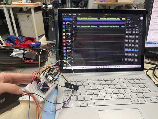
Note becaues it is keep on searching signal so that it give signal frequently
Converting Binary to Hexadecimal
Hexadecimal Basics:
- Hexadecimal is a base-16 number system.
- It uses digits 0–9 and letters A–F, where A = 10, B = 11, ..., F = 15.
- One hexadecimal digit represents exactly *4 binary bits
Steps to convert binary to hexadecimal:
- Group the binary digits into sets of four, starting from the right.
- Convert each 4-bit group to its hexadecimal equivalent.
Example:
Binary: 01001001
Step 1: Split into 4-bit groups → 0100 1001
Step 2: Convert each group → 0100 = 4, 1001 = 9
Hexadecimal: 0x49
Source: ChatGPT by OpenAI, April 2026
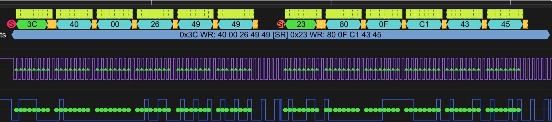
Two packets were identified and the interpretation of it are as follows :
- 1st packet :
- 0x3C WR = This is the 7-bit address of the OLED device (0x3C) combined with a write (WR) operation.
- 0x40 = The following bytes are interpreted as data bytes for the OLED.
- 0x00 (binary: 00000000) = This byte represents pixel data with all pixels turned off.
- 0x26 (binary: 00100110) = This byte turns on the 3rd, 4th, and 6th pixels.
- 0x49 (binary: 01001001) = This byte turns on two pixels separated by gaps.
- 0x49 (binary: 01001001) = The same pattern repeats for the next pixel row.
- 2nd packet :
- 0X23 WR :Appears to be another I2C device. This is typically the address of a BH1750 light sensor; however, since this sensor is not present in the experimental setup, the signal is likely caused by noise.
- 0x80
- 0x0F
- 0xC1
- 0x43
- 0x45
Despite the noticeable noise on the second I2C operation (i.e. the second packet), it appears that the communication is still functioning correctly, which is evident from the first packet with the expected data bytes and the intended device, as well as the acknowledgement (ACK) bit.
SPI communication (Raspberry pi x MOSFET x LED)
The planned final project is a solar PV system that incorporates a power management feature capable of cutting off the power supply if timely payments are not made (see the final project overview for context).
The experiment for this assignment focuses on a simple proof-of-concept prototype with the following setup :
- LED : The load for clear visual indication on whether the system works
- GROVE - MOSFET : The switch. Controlling the power flow.
- Raspberry pi 4 : The controller. Gives signal to MOSFET to turn on or off. In the coming weeks will explore token generation and payment verification. Technical details on this Single-Board Computer (SBC) are available under Details : SBC tab.
- RFID module: Included to experiment with the SPI protocol, which has not been explored in previous assignments. For now acts as a temporary "payment verification"
Python vs MicroPython on Raspberry Pi (SBC)
The Raspberry Pi is a Single-Board Computer (SBC), which means it can run a full operating system (typically Linux). Because of this, it uses standard Python (CPython) rather than MicroPython.
The python code of the setup could be at the admonition below.
RFID x Raspberry Pi 4 x LED code
import RPi.GPIO as GPIO
from mfrc522 import SimpleMFRC522
import time

# --- GPIO setup ---
GPIO.setwarnings(False)          # Disable pin warnings
GPIO.setmode(GPIO.BCM)

MOSFET_PIN = 17                  # GPIO controlling MOSFET/LED
GPIO.setup(MOSFET_PIN, GPIO.OUT)
GPIO.output(MOSFET_PIN, GPIO.HIGH)  # Start with device OFF

# --- RFID setup ---
reader = SimpleMFRC522()
reader.RESET_PIN = 27

print("Hold any RFID tag near the reader...")

try:
    while True:
        try:
            # Wait for a tag
            tag_id, text = reader.read()
            print(f"Tag detected! UID: {tag_id}")

            # Turn off device
The code essentially tells the LED to turn off whenever an RFID tag is present. It could be modified to accept specific tags.
The SPI signals were evaluated using the logic analyzer. It's observed that :
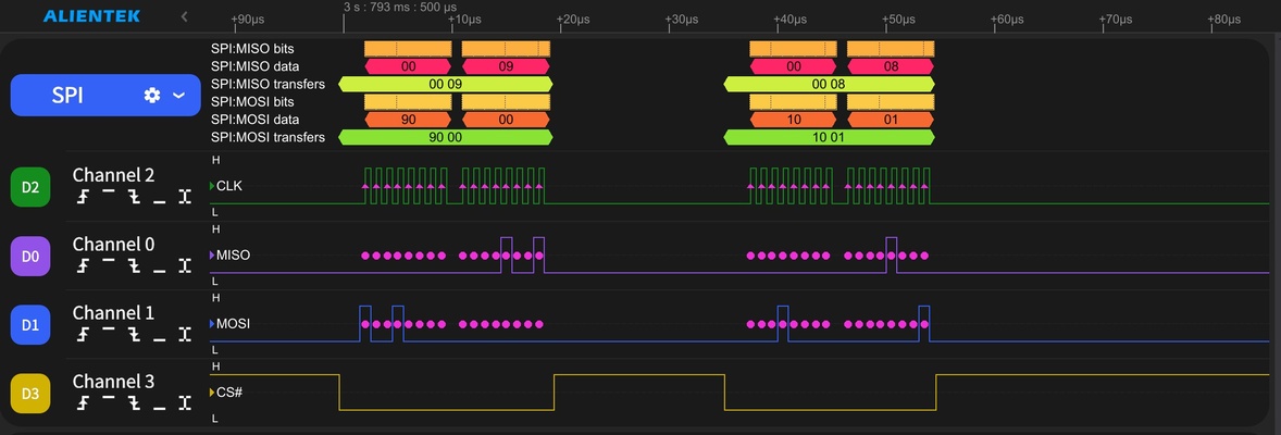
- CS# (D3) is active low and it goes low for the two captured transfers. Note : This is important because SPI allows multiple devices to share the same MOSI, MISO and CLK lines.
- CLK (D2) pulses only while CS# (D3) is low. That is the correct SPI transfer timing.
- MOSI (D1) is sending data while CLK pulses.
- MISO (D0) is returning bytes during those same transfers.
Indicating that the wired communication works properly. However, no further details of the SPI communication is evaluated since the SPI protocol is not standardized across all modules and requires datasheet-specific interpretation.
Further details of the SPI communication are not evaluated, since the SPI protocol is not standardized across all modules and requires datasheet-specific interpretation in comparison to for example I2C. An illustration of it could be seen below.
| Feature | MFRC522 RFID Module | SD Card Module (SPI mode) |
|---|---|---|
| Command size | 1 byte | 6 bytes |
| Addressing | 6-bit register | 32-bit argument |
| Dummy byte | 1 byte required for reads | Sometimes needed |
| Example command | Read register 0x09 → send 0x92 | Read block → send 0x51, 0x00, 0x00, 0x00, 0x00, 0xFF |
Source: ChatGPT by OpenAI, April 2026
Wired/wireless integration (to designed embedded microcontroller system)
Taking this a step further, wireless communication between multiple units of the solar PV system is explored to enable location detection and bidirectional signal exchange. A combination of WiFi and LoRa is tested, as it appears to be robust and suitable for this use case (see the final project overview and the SBC log for more context). Since future integration with cloud services and a payment system is expected, MQTT communication is incorporated into the embedded system to better reflect a more realistic scenario.
Basics of MQTT
Message Queuing Telemetry Transport (MQTT) is a lightweight messaging protocol designed for IOT system.
-
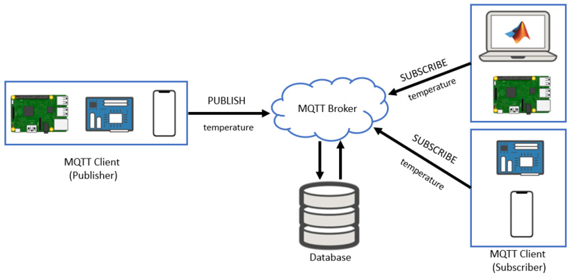
General concept:
- Publish/Subscribe Model : MQTT uses a publish/subscribe communication model instead of direct device-to-device communication. This means devices do not need to know about each other. Instead, they send and receive messages through a central server called a broker.
- Broker : Responsible for receiving all messages, filtering them, and distributing them to the appropriate subscribers. A popular MQTT broker is Mosquitto. Installation method is readily available online.
- Publisher : Any device or application that sends data (messages) to the broker. For example, a temperature sensor publishing temperature readings.
- Subscriber : Any device or application that receives messages from the broker by subscribing to specific topics. For example, a mobile app that displays temperature data.
- Topic : Acts like a channel or label. Publishers send messages to a topic, and subscribers receive messages from topics they are subscribed to.
-
Regarding configuration file:
- The configuration file (
mosquitto.conf) is used to control how the MQTT broker behaves. It is similar to configuration files likemkdocs.yml, because it defines system behavior instead of application code. The configuration file must be created manually by the user. Text editor such as notepad could be used. Ensure that the file is saved with the.confextension (for example:mosquitto.conf) and not as.txt.
- The configuration file (
-
Important command-line options:
moquitto -c→ starts and specify configuration file when starting brokermoquitto -v→ Run broker in verbose mode (useful for debugging)mosquitto -t→ Topic name (used in pub/sub commands)mosquitto -m→ Message content (used in publishing)mosquitto_sub→ Subscribe to topicsmosquitto_pub→ Publish messages to topics
-
Testing MQTT (two terminal i.e. two command prompts method):
- One terminal acts as a Subscriber : mosquitto_sub -t "topic/name"
- One terminal acts as a Publisher : mosquitto_pub -t "topic/name" -m "your message"
Source: ChatGPT by OpenAI, April 2026
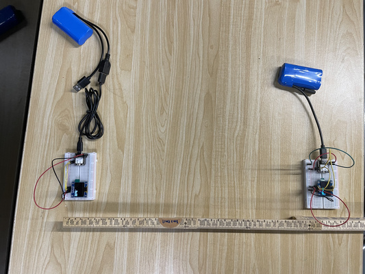
The setup is as follows:
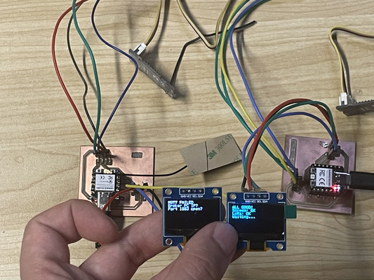
- XIAO ESP32C3 + Grove LoRa Radio 868MHz (left): Handles MQTT communication and acts as the subscriber of messages published via MQTT. It then forwards these messages to the XIAO RP2040.
- XIAO RP2040 + Grove LoRa Radio 868MHz (right): Receives the messages forwarded over LoRa and processes the updates or commands.
The RP2040 is intentionally used in this setup because it does not have built-in Wi-Fi or cellular connectivity (i.e. sim card) - reducing the dependability on reliable internet.
The code for the XIAO ESP32C3 and XIAO RP2040 is shown in the admonitions below, generated using Cursor on April 2026-
XIAO ESP32-C3 x MQTT x WiFi x LoRa Radio 868MHz x OLED
/*
 * ============================================================================
 * XIAO ESP32-C3 — MQTT + WiFi + LoRa SENDER
 * ============================================================================
 *
 * WHAT THIS DOES
 *   1) Connects to WiFi
 *   2) Connects to MQTT broker (Mosquitto)
 *   3) Subscribes to MQTT topic
 *   4) When message arrives → sends it via LoRa to RP2040
 *
 * WIRING (LoRa UART module)
 *   LoRa TX → D7 (ESP RX)
 *   LoRa RX → D6 (ESP TX)
 *   VCC     → 3.3V
 *   GND     → GND
 *
 * OLED (optional status display)
 *   SDA → D4
 *   SCL → D5
 *   VCC → 3.3V
 *   GND → GND
 *
 * MQTT TOPIC
 *   lora/tx
 * ============================================================================
 */

#include <WiFi.h>
#include <Wire.h>
#include <PubSubClient.h>

// ================= EDIT THESE =================
const char* WIFI_SSID = "YOUR_WIFI";
const char* WIFI_PASS = "YOUR_PASSWORD";

const char* MQTT_BROKER = "192.168.1.100";
const int MQTT_PORT = 1883;
const char* MQTT_TOPIC = "lora/tx";
// ==============================================

WiFiClient espClient;
PubSubClient mqtt(espClient);

void sendToLoRa(const char* msg) {
    Serial1.println(msg);
    Serial.print("Sent via LoRa: ");
    Serial.println(msg);
}

void callback(char* topic, byte* payload, unsigned int length) {
    char msg[128];

    if (length > 127) length = 127;
    memcpy(msg, payload, length);
    msg[length] = '\0';

    Serial.println("MQTT Message:");
    Serial.println(msg);

    sendToLoRa(msg);
}

void connectWiFi() {
    WiFi.begin(WIFI_SSID, WIFI_PASS);

    while (WiFi.status() != WL_CONNECTED) {
        delay(500);
        Serial.print(".");
    }

    Serial.println("\nWiFi connected");
    Serial.println(WiFi.localIP());
}

void reconnectMQTT() {
    while (!mqtt.connected()) {
        if (mqtt.connect("esp32_lora_sender")) {
            mqtt.subscribe(MQTT_TOPIC);
            Serial.println("MQTT connected");
        } else {
            delay(2000);
        }
    }
}

void setup() {
    Serial.begin(115200);
    delay(500);

    Serial.println("=== ESP32-C3 MQTT LoRa Sender ===");

    Serial1.begin(9600, SERIAL_8N1, 20, 21);

    connectWiFi();

    mqtt.setServer(MQTT_BROKER, MQTT_PORT);
    mqtt.setCallback(callback);
}

void loop() {
    if (!mqtt.connected()) {
        reconnectMQTT();
    }

    mqtt.loop();
}
XIAO RP2040 x LoRa Radio 868MHz x OLED
/*
 * ============================================================================
 * XIAO RP2040 — LoRa RECEIVER + small OLED (beginner version)
 * ============================================================================
 *
 * WHAT THIS DOES
 *   On power-up it checks: (1) OLED screen  (2) LoRa radio module
 *   Then it waits for text sent over the radio from ESP32-C3.
 *
 * WIRING (IMPORTANT)
 *   LoRa TX → D7 (RX)
 *   LoRa RX → D6 (TX)
 *   VCC     → 3.3V
 *   GND     → GND
 *
 * OLED (I2C)
 *   SDA → D4
 *   SCL → D5
 *   VCC → 3.3V
 *   GND → GND
 *
 * NOTE:
 *   If OLED stays black, check I2C scan or SH1106 compatibility.
 * ============================================================================
 */

#include <Wire.h>
#include <Adafruit_GFX.h>
#include <Adafruit_SSD1306.h>
#include <cstring>
#include <RHReliableDatagram.h>
#include <RH_RF95.h>

static const bool OLED_INVERT_COLORS = false;
static const uint16_t OLED_SCREEN_HEIGHT = 64;

#ifndef PIN_SERIAL1_TX
#define PIN_SERIAL1_TX (0u)
#define PIN_SERIAL1_RX (1u)
#endif

static const uint8_t MY_RADIO_ID = 1;
static const uint16_t OLED_W = 128;

RH_RF95<HardwareSerial> radioDriver(Serial1);
RHReliableDatagram radioManager(radioDriver, MY_RADIO_ID);

Adafruit_SSD1306 screen(OLED_W, OLED_SCREEN_HEIGHT, &Wire, -1);

static bool g_oled_started = false;
static uint8_t g_oled_addr = 0;

static void i2cScanPrint() {
    Serial.println(F("I2C scan..."));
    uint8_t n = 0;
    for (int a = 8; a <= 0x77; a++) {
        Wire.beginTransmission((uint8_t)a);
        if (Wire.endTransmission() == 0) {
            Serial.print(F("  found 0x"));
            Serial.println(a, HEX);
            n++;
        }
    }
    if (n == 0) {
        Serial.println(F("  NO devices — check wiring"));
    }
}

static bool oledBeginAutoAddress() {
    const uint8_t addrs[] = {0x3C, 0x3D};
    for (size_t i = 0; i < sizeof(addrs); i++) {
        if (screen.begin(SSD1306_SWITCHCAPVCC, addrs[i])) {
            g_oled_addr = addrs[i];
            return true;
        }
    }
    return false;
}

void showFourLines(const char* l1, const char* l2,
                   const char* l3, const char* l4) {
    screen.clearDisplay();
    screen.setTextSize(1);
    screen.setTextColor(SSD1306_WHITE);
    screen.setCursor(0, 0);
    screen.println(l1);
    screen.println(l2);
    screen.println(l3);
    screen.println(l4);
    screen.display();
}

void haltForever(const char* msg) {
    Serial.println(F("STOPPED:"));
    Serial.println(msg);
    while (true) delay(1000);
}

void setup() {
    Serial.begin(115200);
    delay(800);

    Serial.println(F("=== RP2040 LoRa Receiver ==="));

    Wire.begin();
    Wire.setClock(100000);
    delay(150);

    i2cScanPrint();

    if (!oledBeginAutoAddress()) {
        haltForever("OLED not found");
    }

    g_oled_started = true;

    showFourLines(
        "OLED OK",
        "System Booting",
        "LoRa Receiver",
        "Starting...");
    delay(2000);

    Serial1.setTX(PIN_SERIAL1_TX);
    Serial1.setRX(PIN_SERIAL1_RX);
    Serial1.begin(9600);

    delay(300);

    if (!radioManager.init()) {
        haltForever("LoRa init failed");
    }

    Serial.println(F("LoRa READY"));
    showFourLines("LoRa OK", "Waiting...", "", "");
}

void loop() {
    if (!radioManager.available()) return;

    uint8_t buf[RH_RF95_MAX_MESSAGE_LEN];
    uint8_t len = sizeof(buf);
    uint8_t from;

    if (radioManager.recvfrom(buf, &len, &from)) {
        buf[len] = '\0';

        Serial.print(F("Msg: "));
        Serial.println((char*)buf);

        showFourLines(
            "NEW MESSAGE:",
            (char*)buf,
            "",
            "");
    }
}
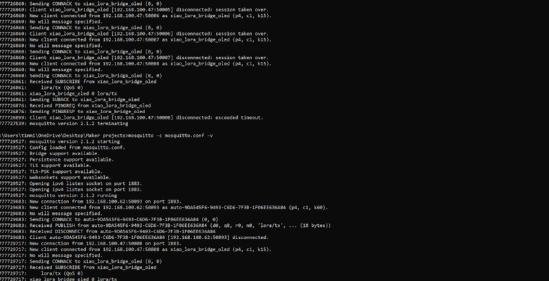
After uploading the code to the microcontrollers, the next step is to start the Mosquitto MQTT broker. A command prompt is opened to run the Mosquitto server with the configuration file (see previous admonition for the command lines). Several messages should appear - indicating that the system is functioning properly.
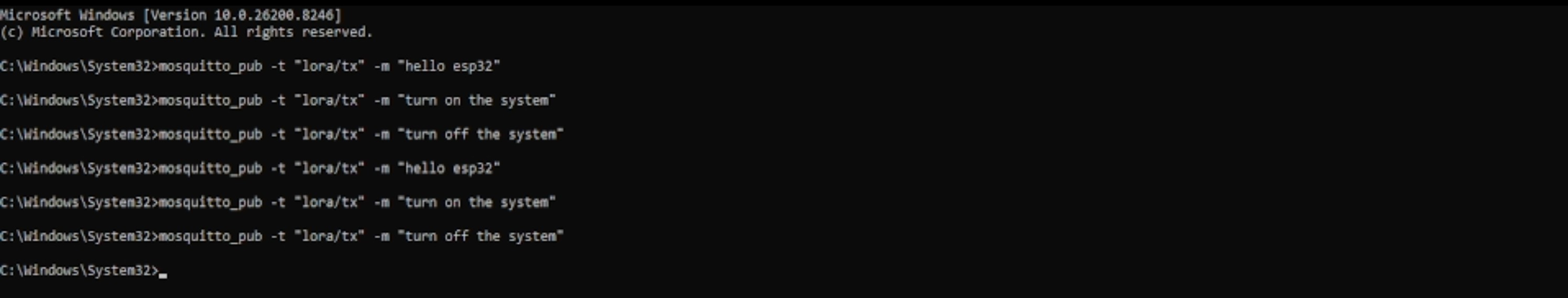
Once the broker is running, a second command prompt is opened. This terminal is used to send messages to the MQTT topic using the mosquitto_pub command. In this case, the messages being sent are “Hello ESP32”, “turn on the system”, and “turn off the system” to the XIAO ESP32C3 and forwarded to the XIAO RP2040.
Apologies in advance for the shaky hands.