Details : MCU + peripherals
Cursor (an AI assistant) was used throughout this log as a research and writing aid — to explain technical concepts, summarise reference material, clarify questions, and help structure and draft the documentation. All explanations were reviewed, tested against the actual build where possible, and verified by the author.
Week 1
-
Week 2
-
Week 3
-
Week 4 : Comparison of motors and light-sensitive sensors
Basics on motors
Other notes regarding motors could also be seen at Week 10 : Output Devices.
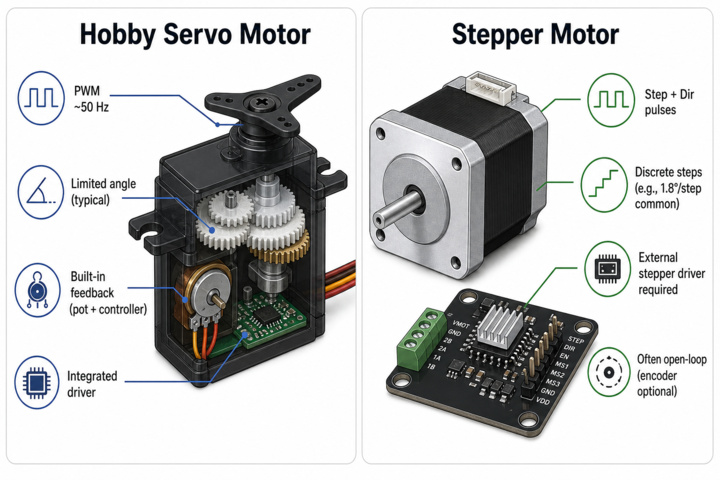
| Feature | Hobby Servo Motor | Stepper Motor |
|---|---|---|
| Typical Motion | Limited-angle rotation (positioning servo) or continuous rotation (modified “360° / CR” servo) | Discrete stepping with fixed angle per step; can rotate continuously through repeated stepping |
| Feedback | Built-in feedback on positioning servos (internal potentiometer + controller) | Usually open-loop (position estimated by counting steps); encoder optional for closed-loop feedback |
| Control Signal | Servo PWM signal (~50 Hz; pulse width determines angle or speed/direction for CR servos) | Step and direction pulses through a stepper driver; often includes current and microstepping settings |
| Positioning Accuracy | Good within limited travel | High repeatability of individual steps; long-move accuracy depends on avoiding missed steps |
| Driver Hardware | Integrated controller inside the servo; requires only power and PWM input | External driver required (e.g., DRV or TMC series driver boards) |
Whether a motor controls speed, position, or both comes from the following :
- What does the control signal command? — a power level (→ speed) or a target angle (→ position)?
- Is there position feedback? — without it, a motor can only be told how hard to spin, not where to stop.
Therefore :
- A plain brushed DC or brushless motor is "speed-native" — apply power and it spins faster ; getting position out of it means adding feedback (an encoder) and a control loop.
- A positional servo is the opposite — it is already a DC motor plus gearbox, potentiometer, and controller in one package, so it accepts an angle command and runs the feedback loop internally. The trade-off is a limited travel range and no direct speed control. A continuous-rotation servo reuses that same package but discards the angle feedback, turning it back into a speed device. -A stepper can be controlled for both position (inferring by counting the steps that is sent and not measured) and speed.
Damping accessories of servo motor
The rubber grommets or bushings help isolate the servo from the mounting bracket. They absorb vibrations generated by the motor and gear train, reducing the amount transmitted to the surrounding frame. In addition, they help distribute the clamping force applied to the thin plastic mounting ears of the servo.

Basics on light direction sensor
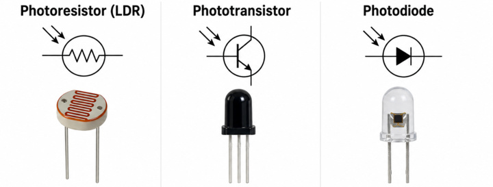
| Feature | Photoresistor (LDR) | Phototransistor | Photodiode |
|---|---|---|---|
| Operating Principle | Resistance changes with light intensity | Transistor activated by incident light | Diode generates photocurrent from light |
| Typical Output | Analog resistance change (usually via voltage divider + ADC) | Analog-like current or digital threshold switching | Small photocurrent or voltage |
| Response Speed | Relatively slow | Faster than LDR | Very fast |
| Circuit Complexity | Very simple | Moderate | More sensitive circuit design often required |
| Advantages | Cheap, simple, easy to interface | Faster response and better directional behavior | High precision and high-speed response |
The most cost-effective option would likely be the photoresistor (LDR). However, since a phototransistor was already available and purchased in Week 3, it is used for the current implementation. In future iterations, switching to a photoresistor could be considered as a potential optimisation if tighter budget constraints become relevant.
Week 5
-
Week 6 : Deep dive on resistors
In almost every microcontroller project, resistors are doing one of a small set of jobs :
- Define a default logic level. Pull-up and pull-down resistors are especially important for ensuring stable startup behavior and preventing floating inputs, particularly when working with newer or less mature chips where internal default states may not yet be fully reliable
- Protect a pin
- Bias a sensor
- Limit LED current
- Controls input drive of a transistor or MOSFET. Ties it to a known default state and so cannot partially turn on.
Value of ±5% is generally fine from the required value of resistor, but a few places like USB need known values to value like 5.1 kΩ.
Week 7
-
Week 8
-
Week 9 : Deep dive on compass, GPS and RTC
The working principals of these devices are explored in this section.
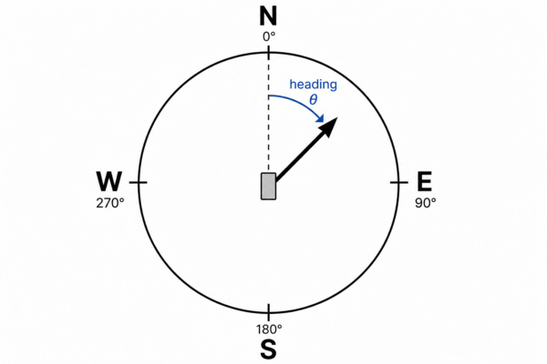
Compass (magnetometer)
A digital compass is essentially a three-axis magnetometer that measures the strength and direction of the Earth's magnetic field along the X, Y, and Z axes. These measurements are typically obtained using magnetoresistive or Hall-effect sensing elements and are communicated to a microcontroller via interfaces such as I²C.
The device's heading (compass direction) is calculated from the horizontal X and Y magnetic field components. This heading is expressed as an angle measured clockwise from magnetic north, indicating the direction in which the device is facing.
One challenge with magnetometers is their sensitivity to nearby ferromagnetic materials, electrical currents, and other sources of magnetic interference. These effects can distort the measured field and lead to inaccurate headings. Calibration procedures are therefore commonly used to compensate for sensor offsets and environmental magnetic disturbances.
In many applications, the magnetometer is paired with a three-axis accelerometer. The accelerometer measures the direction of gravity, allowing the system to determine which way is "down". This information can then be used for tilt compensation, whereby the magnetic field measurements are mathematically rotated back to a horizontal reference plane before the heading is calculated. This significantly improves compass accuracy when the device is not perfectly level.
Several options were available off-the-shelf during the time of this writing, namely :
- Grove – 6-Axis Accelerometer & Compass v2.0 (LSM303D).
- Grove – IMU 9DOF (ICM-20948) — accelerometer + gyroscope + magnetometer (9-axis).
- Grove – IMU 10DOF (adds a BMP280 barometer on top of a 9-axis IMU)
Gyroscope is usually needed to sense check whether the magnetometer is correct due to magnetic interference. In addition to that, for this project it only needs a rough north reference. Pressure reading is also not needed and so the 6-Axis Accelerometer & Compas v2.0 is chosen for the project.
GPS
A GPS (GNSS or Global Navigation Sattelite System is an umbrella term for any satellite positioning system and GPS is specific to the US) receiver listens to radio signals from a constellation of satellites. Each satellite broadcasts its own position and a very precise timestamp. By measuring how long each signal took to arrive (its time-of-flight), the receiver works out its distance to each satellite ; with four or more satellites it can solve for latitude, longitude, altitude, and its own clock offset — a process called trilateration.
NMEA sentence is the default text format GPS modules use to report data over serial. This could be easily parsed to get human readable information.
The Grove - GPS is used simply because it's off the shelf.
RTC
An RTC keeps accurate time even while the main system is powered down, using a small backup cell and a timing reference. The start time could be set through a library.
GPS and RTC are complementary for the following reasons :
- GPS only gives time once it has a fix — which needs a clear sky view and can take seconds to minutes (cold start). I
- Instant availability at boot
- Power — GPS draws far more current; you don't want it running continuously just to know the time. The RTC sips microamps and runs for years off a tiny backup cell.
Two common families were compared :
| Topic | DS1307 / PCF8563 | DS3231 Family |
|---|---|---|
| Oscillator Concept | Uses an external crystal whose frequency can drift with temperature changes | Integrates temperature compensation around an internal timing reference (TCXO-style approach) for improved stability |
| Typical Timekeeping Behavior | Can exhibit noticeable drift when environmental temperature changes | Maintains significantly more stable and accurate civil time over varying temperatures |
| Cost / Complexity | Lower cost and simpler implementation | Higher cost with additional internal compensation circuitry |
| Sleep / Backup Current | Often very low depending on crystal and board design | Still low in absolute terms, but not always lower than simple crystal RTCs ; depends on operating voltage and IBAT characteristics |
The PCF8563 is chosen because the pairing with GPS already gives enough possibility for re-sync of the clock without the need to be temperature compensated.
Week 10
-
Week 11
-
Week 12-13
-
Week 14 : Custom PCB fabrication
The board brings the two core electrical function :
- The MCU, in this case the esp32-devkit as the controller of the system
- Load switching circuitry that drives the lock. the high-side MOSFET switch detailed in the Power supply log
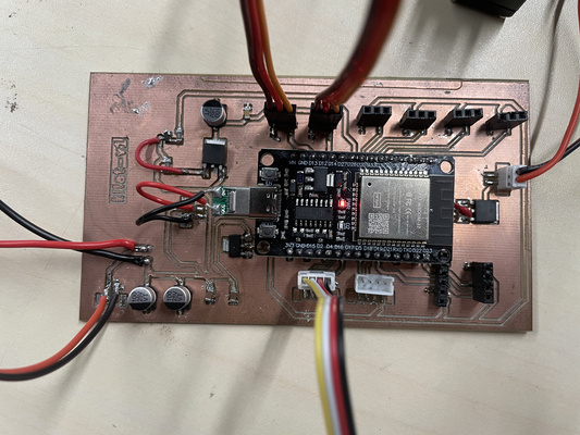
During the test, the N-channel was wired incorrectly and the MOSFET burnt out. The section therefore need to be corrected and re-soldered by hand by a short jumper wire.
A JST connector system was considered instead of plain soldered wires to make the wiring mechanically mor robust. Thus, the crimping technique (i.e. manually) was attempted but the quality of the result turned out poor. Lessons learnt were :
- Correct crimp tool is needed for the relevant size.
- Housings come in different sizes and the right wire gauge must be used to ensure the right fit.
| JST series | Pitch | Typical wire |
|---|---|---|
| SH | 1.0 mm | ≈ 28–32 AWG |
| PH | 2.0 mm | ≈ 24–30 AWG |
| XH | 2.5 mm | ≈ 22–30 AWG |
| VH | 3.96 mm | ≈ 16–22 AWG |
Typical current ranges to ~1–3 A for this family. For higher current, the XT family could be used (i.e. XT30 ≈ 15–30 A, XT60 ≈ 60 A, XT90 ≈ 90 A).
Perhaps buying the pre-made ones are better after all.
The PCB was successfully validated through initial testing and appeared to function as intended. With the design verified, the board files were then submitted to JLCPCB for commercial fabrication of the final revision.
Week 15 : System architecture test
The test followed a command along the whole chain : a lock / unlock issued from the web interface travels server → MQTT → LoRa → MCU, and the MCU acts on it by toggling the load switch. Confirming that an instruction sent from the interface actually reaches the device and changes the output.
As shown in the video above, the servo successfully moves to its centre position during startup abd at the same time, the battery charging indicator lit up (confirming that it is charging) - the system works!
Week 16
-
Week 17
-
Week 18
-
Week 19
-
Week 20
-