Overview
Full-stack overview
%%{ init: { "themeVariables": { "fontSize": "18px" } } }%%
flowchart TB
    classDef power fill:#FFF1C9,stroke:#E0A800,color:#5c4500;
    classDef rail  fill:#FFE0B2,stroke:#E65100,stroke-width:1.5px,color:#3e1f00;
    classDef ctrl  fill:#D7E8FF,stroke:#1565C0,color:#0d2b4f;
    classDef sense fill:#D9F2D9,stroke:#2E7D32,color:#143d16;
    classDef load  fill:#ECECEC,stroke:#616161,color:#222222;

    SUN["☀ Sun"]:::power
    PANEL["`Solar panel
(east–west tracker)`"]:::power
    REG["Solar regulator → 5 V"]:::power
    BATT["UPS battery pack"]:::power
    RAIL5["5 V rail"]:::rail
    LDO["LDO"]:::power
    RAIL33["3.3 V rail"]:::rail
    WEBUI["`Web interface
(Vercel)`"]:::ctrl
    PI["`Raspberry Pi
Node-RED · MQTT`"]:::ctrl
    ESP["`ESP32 DevKit
(MCU)`"]:::ctrl
    LOADS["`5 V loads
Phone charging
Servo MG996R`"]:::load
    INPUTS["`3.3 V inputs
Phototransistor
Grove compass V2
RTC PCF8563`"]:::sense
    OLED["`3.3 V output
OLED 2.42″ SSD1309`"]:::sense

    %% power (solid)
    SUN --> PANEL --> REG --> BATT --> RAIL5
    RAIL5 --> LDO --> RAIL33
    RAIL5 -->|USB-C| ESP
    RAIL5 --> LOADS
    RAIL33 --> INPUTS
    RAIL33 --> OLED

    %% control & data (dotted)
    WEBUI <-.->|Cloudflare tunnel| PI
    PI <-.->|LoRa 868 MHz| ESP
    ESP -.->|lock / unlock| LOADS
    INPUTS -.->|sensor data| ESP
    ESP -.->|display| OLED

    %% layout: stack the device groups on their own rows (invisible links)
    LOADS ~~~ INPUTS ~~~ OLED
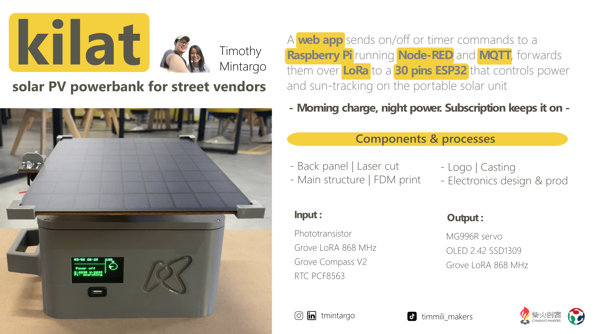
- A solar panel on a single-axis (east–west) tracker charges a UPS battery pack.
- A remote lock / unlock command (server → MQTT → LoRa → ESP32) switches a high-side MOSFET that powers the user load — the pay-as-you-go mechanism.
- Power is split into two rails : a 5 V rail (from the solar regulator and UPS battery) runs the loads and feeds the ESP32 over USB-C, and an LDO drops it to a 3.3 V rail for the sensors and display.
- The ESP32 reads the phototransistor to find the sun's direction and drives the MG996R servo to keep the panel facing it.
- The Grove compass lets the user line the unit up to north at install, while the RTC (PCF8563) keeps time for the tracking schedule and billing even with no power or network.
- The OLED display shows the system status (charge, lock state, etc.).
- The control interface is a web app hosted on Vercel, linked through a Cloudflare tunnel to Node-RED + MQTT on the Raspberry Pi, which bridges the commands out over LoRa (868 MHz) to the ESP32.
The full week-by-week build and the technical detail are in the logs below.
Documentation
The detailed process is documented week-by-week and in the per-system logs :
Detail logs
- General log — week-by-week build
- MCU + peripherals log
- Power supply log
- SBC (server) log
- Mechanical structure log
- Payment system log
Most relevant weekly assignments
- Week 15 — Interface & application programming — the control web interface
- Week 16 — System integration — control-unit design and integration
- Week 18 — Project development — BOM, cost analysis and evaluation
- Week 19 — Invention, IP & income — licensing
Design & source files
| File | Description | Download |
|---|---|---|
| KiCad project | Schematic + PCB for the MCU + load-switch (lock) board | pcb-kicad.zip |
| 2D and 3D design | 3D-printable tracker head, telescopic mast part, control-unit enclosure | 2D-3D-design.zip |
| Firmware | ESP32 control loop + lock logic + LoRa command handling | firmware.zip |
| Server / interface | Raspberry Pi LoRa bridge + Node-RED flow + web UI | server.zip |
Licence
- Firmware : MIT
- Hardware, designs, and documentation : CC BY-NC-SA 4.0