Details : Mechanical structure
Cursor (an AI assistant) was used throughout this log as a research and writing aid — to explain technical concepts, summarise reference material, clarify questions, and help structure and draft the documentation. All explanations were reviewed, tested against the actual build where possible, and verified by the author.
Week 1
-
Week 2
-
Week 3
-
Week 4
-
Week 5
-
Week 6
-
Week 7
-
Week 8
-
Week 9
-
Week 10 : SG5010 x solar panel load test
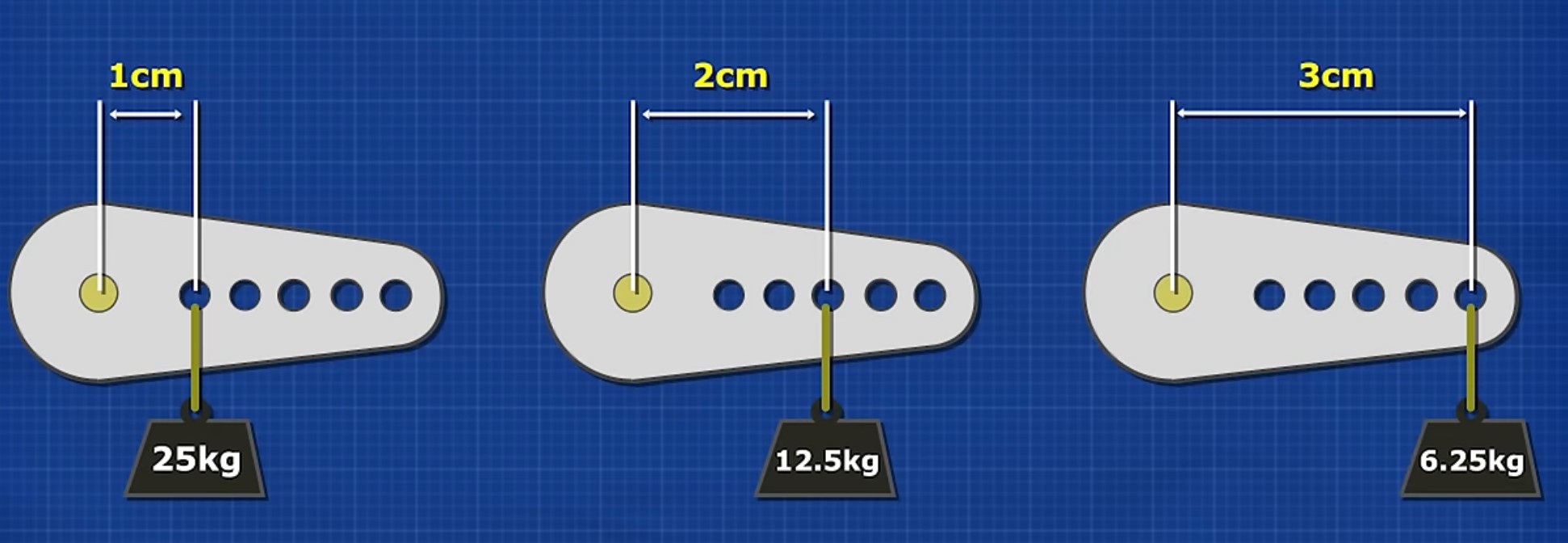
Torque is force multiplied by the lever-arm distance from the pivot :
and so the servo must provide more torque than would be suggested by the panel's weight alone, as the load's center of mass is offset from the pivot point. This creates a moment arm that increases the torque required to both move and hold the panel in position.
The video below shows the results of the load test.
Two key observations were made:
- The SG5010 servo did not provide sufficient torque to move and hold the panel reliably under load. A higher-torque servo will therefore be required.
- The clamp/mount used during testing exhibited instability, including rocking and a tendency to tip due to its structural design. A four-legged mount is expected to provide improved stability by distributing the load more evenly.
Week 11
Week 12-13 : Main structure fabrication and testing
The structural work moved from a off-the-shelf clamp to a purpose-made assembly. Three things were tackled this week :
Tracker head + mast — design and fabrication
Following the Week 10 wobble, the structural work moved from a borrowed clamp to a purpose-made assembly. Three things were tackled this week :
Tracker head + mast — design and fabrication
The 3D CAD model is shown below :
An extra design goal from here besides the mechanism is on the wiring. Visible wiring should be close to none and whenever possible should be routed internally e.g. hollow mast with channels for the cable from the solar panel to the control unit.
The results of the fabrication could be seen at the next section.
Extendable mechanism
The mechanism has to extend strictly vertically to save space. Several ways to lock a vertical telescopic mast at a chosen height were considered :
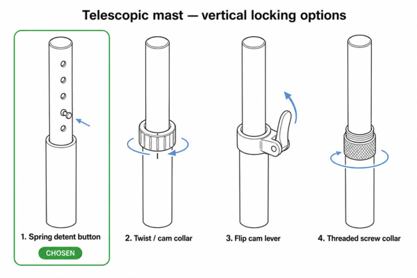
In the end the spring detent button was chosen. The intention is that the panel / mast can retract fully and sit cleanly flush against the face of the control-unit casing. The collar-style locks (twist / cam collar, flip lever, threaded screw collar) all wrap around the tube and stick out, which would leave a gap between the mast and the casing and stop it seating cleanly. The threaded screw collar is also not user-friendly — the user would have to keep manually untwisting it to free the mast and re-tighten it at the right level.
MG996R × solar-panel load test
The final project documentation demonstrates the resulting implementation. The mast structure performed as intended and remained stable throughout testing, with no signs of toppling. It is expected that integrating the mast with the final enclosure will further improve stability by providing a wider and more secure base.
Week 14
-
Week 15
-
Week 16
As mentioned, details on the design of the enclosure could be seen at Week 16 System Integration. The full design of the product though is shown below.
It was estimated that printing the control-unit enclosure would require up to 13 hours, making failed prints both time-consuming and material-intensive. To reduce this risk, critical features and interfaces were first printed as smaller test pieces to verify dimensional accuracy and fit before committing to the full print.
This process was made straightforward using the slicing software's cut tool, which allows selected sections of the model to be isolated and printed independently. Fortunately, access to a BambuLab H2S with a larger build volume than the standard A1-series printers was also available, reducing the need to split the enclosure into multiple printed parts.
Week 17 : Logo casting + deep-dive fluorescent
The casting in this case is unforgiving and gives very little room for mistake especially due to the long printing duration of the enclosure. Thankfully, due to the experiments done in Week 16 with the separate features, it was found out that IPA could help clean up small imperfections.
It was noted at this stage, after more research the following points :
- Fluorescent — glows only while it is being lit (usually by UV or blue light), re-emitting it almost instantly as a brighter visible colour. Remove the light and it stops — no afterglow. Phosphorescent ("glow-in-the-dark") — stores absorbed light and keeps glowing on its own in the dark for minutes to a couple of hours, fading until recharged by light.
- Fluorescent/phosphorescent pigments are limited
Therefore, future iterations may benefit from incorporating programmable LEDs instead to obtain consistent illumination and control over color of choice.
Week 18
-
Week 19
-
Week 20
-