Week 14 : Molding & Casting
Molding generally refers to the process of creating a cavity or negative shape into which a material can later be poured or injected. The process of filling the mold with material is commonly known as casting. In comparison to 3D printing, this technique :
- Enables the production of multiple copies of the same shape efficiently, particularly for materials that are not suitable for direct 3D printing.
- Produces smoother surface finishes with fewer visible layer lines or support marks compared to many additive manufacturing methods.
Week 14 assignment could be categorized as follows:
-
Group assignment
- Safety data sheet comparison of materials
-
Individual assignment
- Mold design (with smooth cast surface)
Additional details beyond those presented in this document can be found in the Chaihuo's 2026 Week 14 group documentation.
Basics of molding and casting
-
Molding (the tool) : Physical form or cavity used to shape a material
- Types :
- One-piece
- Two-piece
- Multi-piece (three or more piecess)
- Components (this is more relevant to two-piece and multi-piece molds):
- Sprue : Main channel through which molten material enters the mold
- Runner : Pathways that distribute material from the sprue to different cavities
- Gate : Small operning where material enters the final part cavity
- Vents : Small channels that allow trapped air to escape during filling
- Parting line : The interface where two mold halves meet
- Materials :
- Low-temperature wax/machineable wax
- Foam
- Alginate gel : used for body or face casting
- Urethane : very common. requires good ventilation due to fumes during curing
- Silicone : flexible and easy to demold. inert (safe and chemically stable) material. does not require strong ventilation
- Calcium sulfate (gypsum-based) : recommended. rigid and stone-like feel.
- Metal (low-melting alloys) : tin-bismuth and similar alloys. used for reusable or high detail molds
- Ceramic : used for high-temperature or durable mold applications
- Epoxy : transparent molds
- Behavior :
- Thermoplastics : can be melted and reshaped multiple times
- Thermosets : cure permanently and cannot be remelted. generally stronger and more heat-resistant after curing.
- Types :
-
Casting (the product/process) : Pouring or injecting material into the mold. Solidified part.
-
Mold-cast material relationship :
- Soft cast, rigid mold
- Rigid cast, flexible mold
-
Additives :
- Glass fibers : reduce density and can improve stiffness
- Short fibers : increase tensile strength
- Conductive fillers (e.g. carbon)
-
Processing techniques :
- Mixing : avoid scooping motions that trap air and create bubbles. stir gently in flat, consistent motion
- Pouring : do not dump material directly into the mold. pour slowly to allow air to escape and reduce bubble formation
- Curing : many materials are exothermic (i.e. generate heat). Poor mixing may reduce or prevent expected heat generation.
-
Other notes :
- Shelf life becomes uncertain once a container is opened (e.g. moisture absorption degrades material performance over time)
- Apply releasing agent before pouring mold material. can be commercial sprays or DIY solutions like diluted dish soap.
- Bubble reduction methods include vibrating the mold, vacuum degassing, and using pressure chambers to remove trapped air during casting. If layer lines or surface imperfections are still visible after curing, surface finishing techniques such as painting or coating layers can be applied to improve the final surface quality.
Source: ChatGPT by OpenAI, May 2026
Chemicals should always be treated with respect and handled with appropriate care, even when working with small quantities or during short exposure times. Repeated skin contact could lead to allergic sensitization, vapors and dust may cause eye irritation, etc
Safety data sheet (SDS) comparison of materials
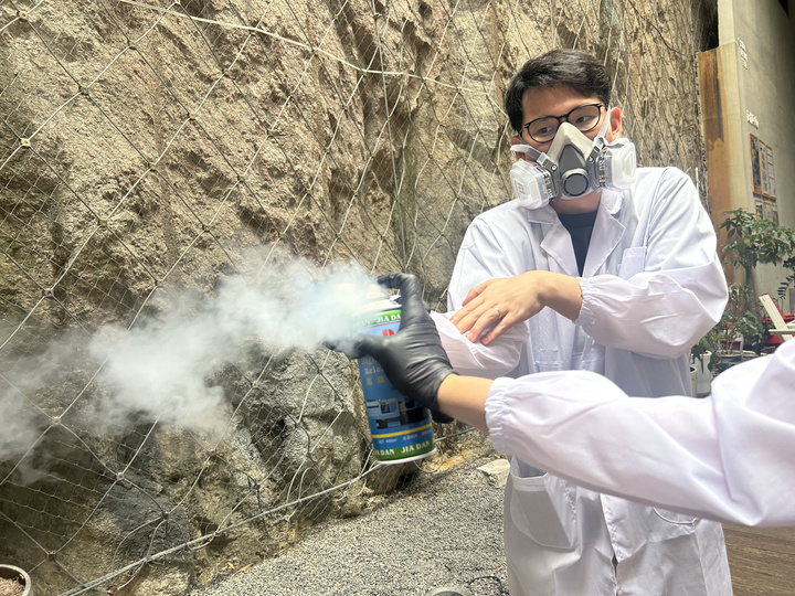
Before opening any bottles, read each SDS and set up ventilation as recommended
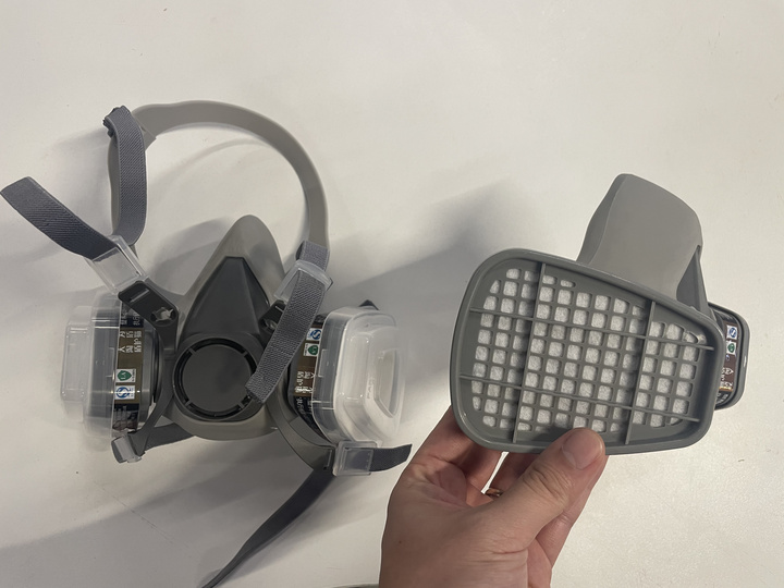
Wear safety glasses, appropriate gloves (i.e. latex vs nitrile), closed shoes, and long sleeves or a lab coat, and appropriate respiratory protection (e.g. with organic filters is recommended) - dust mask is not enough for chemical fumes
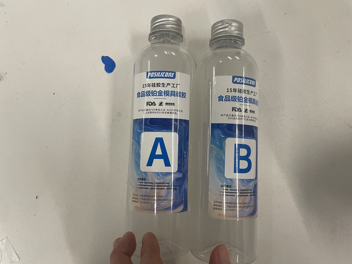
The following materials represent the primary casting and molding materials :
| Field | Details |
|---|---|
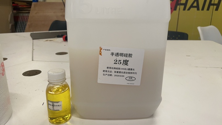
| Mix ratio (by weight) | 100 : 2 (base : curing agent) |
| Special instructions | Stir thoroughly ~1–2 minutes; apply releasing agent before casting for easier demolding (see the next sections for findings) |
| Full cure | Approx. 2 hours |
| Field | Details |
|---|---|
| Mix ratio (by weight) | 3 : 1 (powder : water) |
| Special instructions | Water first, then gypsum; stir until pourable; brush into fine details, then bulk pour |
| Full cure | Approx. 1 hour |
| Field | Details |
|---|---|
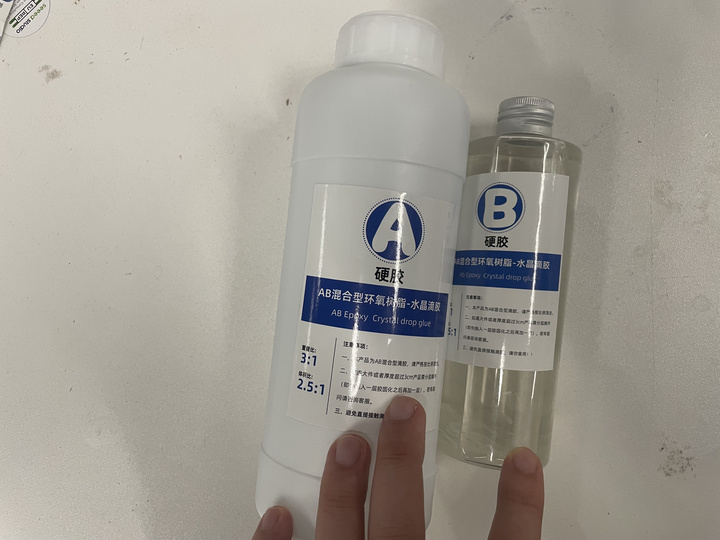
| Mix ratio (by weight) | 3 : 1 (A : B) |
| Special instructions | - |
| Full cure | Approx. 24 hours |
| Field | Details |
|---|---|
| Mix ratio (by weight) | 1 : 1 (A : B) |
| Special instructions | - |
| Full cure | Approx. 6 hours |
In two-part casting and molding systems, Part A generally refers to the base material, while Part B refers to the curing agent, hardener, or catalyst.
Resin is a broad term referring to liquid materials that cure into solids e.g. epoxy resin, polyurethane resin, etc
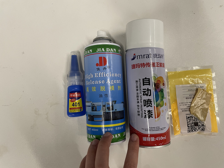
In addition to these base materials, several supporting additives and processing aids were also used during experimentation :
| Material | Key Properties / Usage Instructions |
|---|---|
| Super Glue (Saka 401) | Typical curing time: approx. 3–5 minutes. In case of skin contact, remove using warm soapy water. Avoid wearing gloves that may accidentally bond with the adhesive during handling. |
| Oil-Based Release Agent | Hold spray can approximately 25–30 cm from the target surface during application. Do not operate the can upside down. Suitable for plastic, rubber, metal, and glass surfaces. |
| 3D Print Spray Paint/coating | Hold spray approximately 25–30 cm from the surface. Drying time: 10–15 minutes (surface dry), full curing approximately 48 hours. |
| Fluorescent Powder | Used for aesthetic enhancement and visual effect demonstrations. Helps illustrate differences between 3D printing, molding, and casting finishes. |
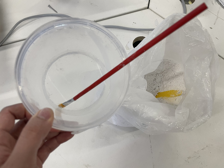
Prepare kitchen towels or disposable wipes before starting the process, as some materials can become messy during mixing and application. Certain compounds may also harden quickly and so immediate clean up might be essential. Isopropyl alcohol could aid with the cleaning - though caution should be exercised for some materials
Mold design
The design concept was inspired by the work of Lei Feng’s Week 14 : Molding and Casting documentation. The idea was further adapted to reflect the year 2026 with the hope that if satisfactory, the final pieces could serve as meaningful and memorable gift.
The logo was first exported as an SVG file and then converted into a DXF format using Inkscape. The DXF file was subsequently imported into Onshape, where it was interpreted as a sketch. From there, the 2D geometry was transformed into a 3D model using the Extrude feature. This becomes the "master" of the mold.
The mold design used in this experiment follows a three-part construction approach of rigid-soft-rigid that will be further explained in the next sections:
- Rigid : The "master"
- Soft : Silicone
- Rigid : Cast materials
Alternative two-part mold strategies are also perhaps possible depending on geometry complexity and material selection; however, those approaches were not explored at the time of writing this documentation.
Masters
The master refers to the original positive model used to create the mold cavity. Since the surface finish of the final product is directly determined by the quality of the master, special attention is given to its preparation and finishing.
FDM
The workflow follows the procedure implemented during Week 5 : 3D scanning and printing. Additional print settings (advanced) at the BambuLab A1 were applied to achieve a smoother surface finish.
- Print profile: 0.08 mm Extra Fine @ BBL A1M
- Ironing: Enabled
- Ironing type: Topmost Surface
- Ironing pattern: Rectilinear
- Ironing speed: 30 mm/s
- Ironing flow: 8%
- Ironing line spacing: 0.10 mm
- Ironing inset : 0.21 mm
The ironing feature instructs the printer to perform an additional pass over the top surface at the same Z height - the combination of melted filament that flows to the small gaps between printed lines and heat from nozzle that slightly softens top layer slightly enables a smoother finish.
For more details on the parameters, please refer to the official BambuLab documentation.
However, visible layer marks could still be observed on the print surface.
The following approach was therefore experimented :
- Layer of 3D print spray filler was applied
Spray application handling
It is recommended to hold the part using a scissor tong or clamp rather than by hand while applying the spray.
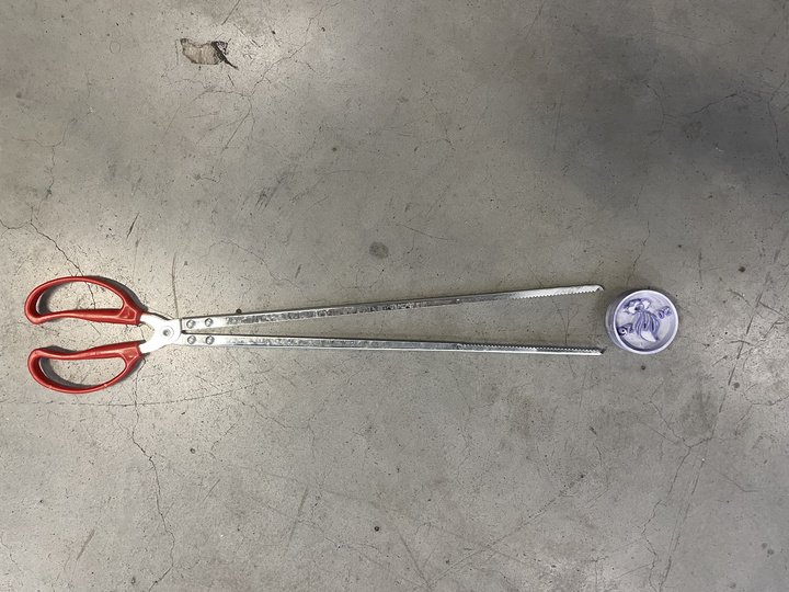
In practice, spray filler appears to work better on exposed outer surfaces than on intricate inner features especially if it dries quickly. A brush-applied liquid filler may provide better control and should be explored in the future
-
Progressive sanding was carried out using increasingly finer grit sizes, applying a light rotating motion without excessive pressure. In this experiment, the sequence used was 120 grit → 400 grit → 1200 grit, followed by a final wet sanding step that allows finer abrasive particles to glide more smoothly over the surface. The piece at the left and right shows the result of the reachable surface before and after spray filler, and sanding.
It was observed that this method helped reduce surface imperfections to some extent. However, the geometry — and possibly the scale — of the design included tight internal corners and narrow gaps, making it difficult to sand and refine the surfaces uniformly even with techniques like attaching the sanding paper to chopstick.
Due to these limitations, it was decided to look for other master fabrication alternative. Nevertheless, it is noted that this the approach remains suitable for simpler geometries with more accessible surfaces as demonstrated in Eka Prawira's Week 12 documentation
SLA
SLA printers like the Formlabs 4 could operate at 0.100 mm, 0.050 mm to even 0.025 mm layer resolution. It is important to note though that although FDM printer could be set a printed slice of 0.08 mm, FDM stacks extruded molten filament and therefore typically leaves strong layer lines - while SLA often gives smoother and finer features at similar layer height. Thus, this technique is used to evaluate its potential to achieve improved surface quality.
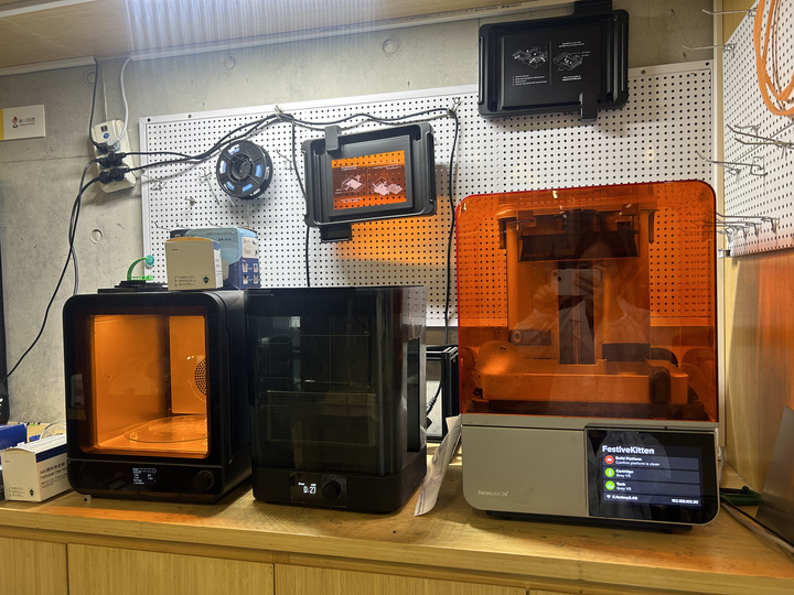
For context, the following two components of the resin printer will be referenced throughout the workflow and are therefore worth introducing here :
- Resin tank : Container of the resin.
-
Build platform : Surface onto which the printed part is formed.
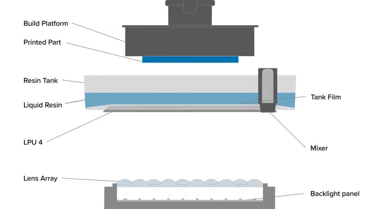
Source : Formlabs
Design
Similar to the Bambu Lab slicer workflow, PreForm is the slicing software used for Formlabs printers. Several settings needed to be configured before printing:
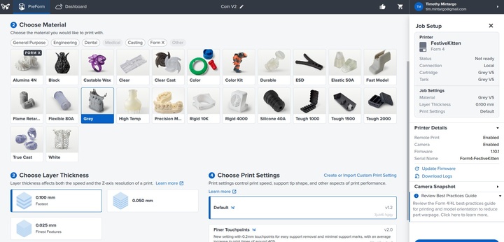
-
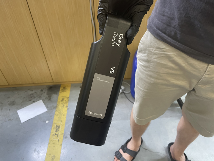
Printer and resin material selection : Wrong selection could lead to print failure such as the peel (i.e. force to separate the cured layer from the resin tank after exposure) settings. In this case the Grey V5 resin was used.
-
Layer thickness selection : Thinner layers generally improve surface finish and fine detail reproduction, but they also increase print duration. For this experiment, a layer thickness of 0.1 mm was selected.
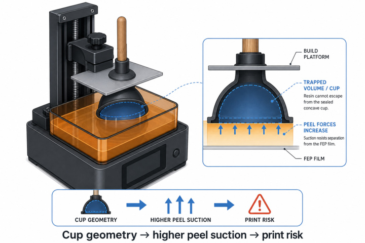
The next step is to configure the print orientation. The automatic orientation tool at the top right of the slicer can be used iteratively until a robust setup is achieved. This typically involves adequate support, minimizing the number of required supports especially on the main face of interest and avoiding problematic conave geometries that can create suction effect like a toilet plunger.
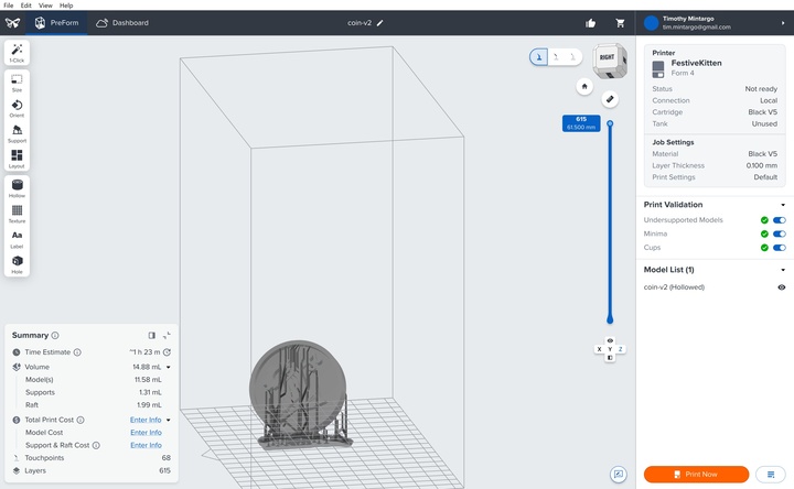
The image below is generated by cursor AI and should only be taken as a reference.
For more detailed explanations aregarding SLA print parameters and advanced setup considerations, please refer to the official Formlabs PreForm Documentation.
The Formlabs Form 4 package consists of the printer itself, an isopropyl alcohol (IPA) wash station, and a UV curing station. The overall workflow are outlined below.
Printing
MSLA stands for masked stereolithography (also called masked SLA). The working flow are as follows starting from the :
- Liquid photopolymer resin (the material for the print) sits above a transparent window.
- For each layer (equivalent to FDM printing), the printer's light engine projects a 2D image of the slice onto the resin. One layer cures at once
- The build platform starts near the film and lifts slowly
- The wiper (mixer) stirs resin so viscosity and temperature stays uniform at the resin tank
- Process repeats until the full geometry is solid
The following needs to be checked before printing starts (in general the printer interface typically displays these checks as well on the machine's monitor) :
- Resin tank condition : Clean and free from debris or previously cured (hardened) resin
- Build platform : Clean and properly attached
- Resin cartridge : Cap or valve is open so resin can flow into the tank during printing
Uncured resin residues left on tools or surfaces can be placed under sunlight (UV exposure). The resin will gradually cure and harden on its own. Once solidified, it can be safely removed using a plastic scraper without damaging the underlying surface
Once the print is started, the final part is produced in an upside-down orientation on the build platform. The flexible build platform can be gently flex (i.e. pinched) to help release to remove the parts. The uncured part could then be transferred to an IPA bath for cleaning to remove remaining liquid resin before post-curing.
IPA bath
The cleaning process is relatively straightforward : the part is submerged in the isopropyl alochol bath and gently agitated for several minutes until the excess resin is removed. Every resin name + version has recommended wash times. For Grey V5, it's 5 minutes.
Short drying should be done before moving into the UV process.
Isopropyl alcohol (IPA) used for cleaning can be left in an open, well-ventilated area exposed to sunlight due to it's low boiling point
The IPA in the wash bath should be regularly monitored and replaced when it becomes saturated with dissolved resin (i.e. uncured resin are accummulated so much until the cleaning performance are reduced). A good indicator for replacement is when the liquid appears cloudy or when cleaning efficiency noticeably decreases
It is recommended to remove the supports at this stage, as they are easier to detach while the material is still less rigid compared to post-UV curing - which could lead to increasing risk of leaving marks. The supports were actually more difficult to remove cleanly despite the part being thinner than a typical FDM print.
UV curing
The printer partially cures each layer enough to build the shape but to reach full hardness and stable material behavior, the UV curing station is needed.
The curing parameters also is dependent on the resin used. For Grey V5, curing time is recommended to be 5 min with no heat.
Mold boundary
Two methods were explored to define the outer boundary for the silicone pour: a LEGO-built mold wall and an FDM-printed boundary. The latter was investigated simply as another alternative that could be reused across different models in future workflows - as anyways the surface finish of the boundary itself was not critical.
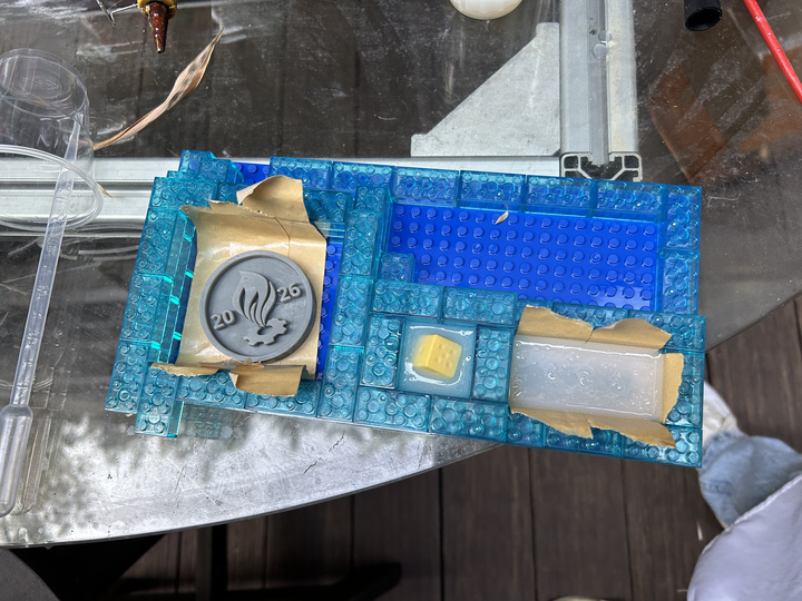
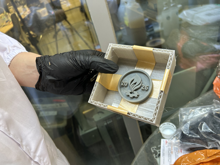
It is important to note that the master may float or shift during the molding process due to the buoyancy effects between the poured silicone and the printed material. Thus the master is secured by first laying clear packing tape on the base plate - important only one side sticks - and then super glue Saka 401 is applied selectively between the master and the other side of the tape.
When pouring silicone or casting materials, pour slowly and steadily to minimize trapped air. Observe the flow carefully for bubbles forming during the pour and wait for it to surface. Redirect the pouring stream toward the bubble location and allow the weight and gravity of the liquid to help stretch and break the bubbles
The tape played a bigger role on the FDM-printed boundary as it acts as a practical release layer between the silicone and the work surface.
In contrast, the modular LEGO "wall" can simply be disassembled after curing. The process of removing the master from the mold took even longer time.
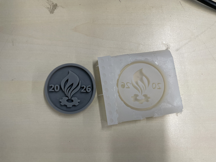
Mold result
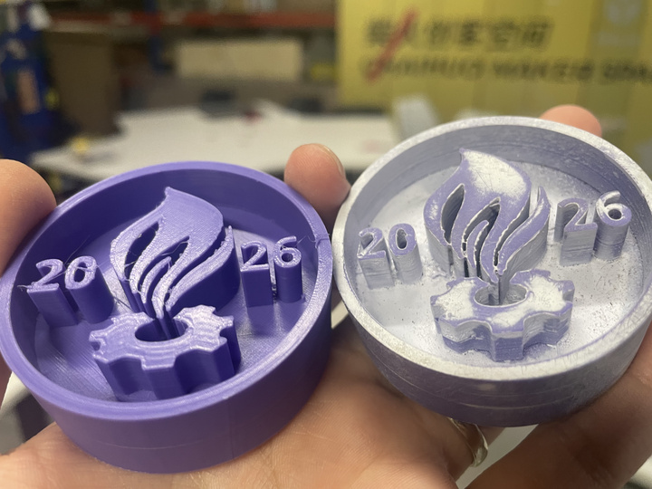
The mold faithfully copied the master surface as expected. The FDM-based masters clearly showed clear layer stepping especially on curved and shallow-angled regions that were left as-printed without sanding. This gives a clear signal that only the SLA master - silicone mold should be brought forward to the casting stage. Only the latter is shown for reference.
Cast result
Test release agent before full use
It is recommended to perform a small-scale test before applying any release agent to the full mold. The tests below shows that most of the time release agent is not actually required as the cured silicone is flexible enough for clean demolding on its own. In fact, a negative affect on curing or surface quality might actually be introduced if there's incompatibility between the material.
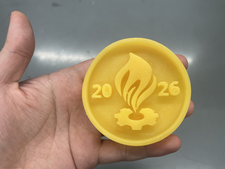
Three materials were tested :
- Polysilicone + fluorescent powder
- Gypsum (calcium sulfate)
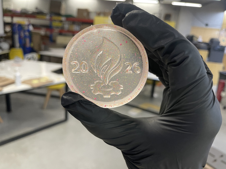
- Epoxy "crystal" resin + glitters
Chemicals and uncured resins or silicone mixtures should not be disposed of down the drain. It is recommended to fully cure these materials first that allows them to become inert solid waste before disposal in the appropriate waste container
Polysilicone + fluorescent powder
This experiment was carried out unintentionally after the material was mistakenly identified as epoxy crystal resin. Nevertheless, several interesting lessons and observations were still gained from the process. The incorporation of yellow fluorescent powder into the casting produced a visually appealing effect and so is also worthwhile to share.
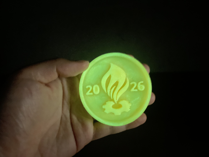
The visual effect is nice under dark lighting conditions. In reality a noticeable oily or "sweaty" surface was present.
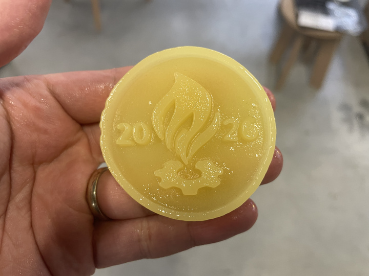
The release agent was initially suspected to contribute to the oily or “sweaty” appearance observed at the casting interface; this had also been used during the mold-making process but similar effect was not previously observed. However, follow-up test conducted without any release agent still produced a similar surface effect. This suggests that the root cause may instead be related to the silicone-to-silicone interface itself potentially due to material incompatibility (e.g. mismatch between tin-cure and platinum-cure silicone systems). Since the material data sheet did not clearly specify this compatibility information, a definitive conclusion could not be made.
The defect though seems to only appear primarily at the surface. Wiping/washing with IPA was tested and it indeed reduces the greasy fill.
Epoxy "crystal" resin + glitters
The workflow for this material is straightforward and closely resembles that of polysilicone. A release agent was intentionally omitted, as earlier trials indicated that the silicone mold is already sufficiently flexible to allow clean demolding.
Some minor imperfections remain in the recessed details. Introducing additional vibration or light tapping during processing may help the material distribute more evenly. Overall, however, the result appears satisfactory.
Gypsum (calcium sulfate)
The mix in this case does not require the same precision as two-part chemical systems mentioned earlier. However, viscosity plays a critical role in the final result. If the slurry becomes too thick (similar to Greek yoghurt) it will be difficult to flow into fine details. The ideal consistency is observed to be closer to a pourable, drinkable yoghurt: it should flow when the cup is tilted, yet still retain a slightly milky body. The video below demonstrates a slurry consistency that is still too viscous for optimal flow into the fine details.
Furthermore, gypsum begins to set quickly and so time is a critical factor during operation. A brush can be used initially to work the mixture into fine textures and recessed areas before the bulk pour.
Powder landing into water breaks apart more easily rather than the other way around. This leads to reduced risk of hard clumps forming and so the opposite method is more recommended
The final result shows generally good surface reproduction although slight imperfections are still visible. This is perhaps due to dust or small persistent surface contaminants present during casting. More effective cleaning should be explored in the future but for now, the outcome is stll acceptable and represents a clear improvement over previous tests.
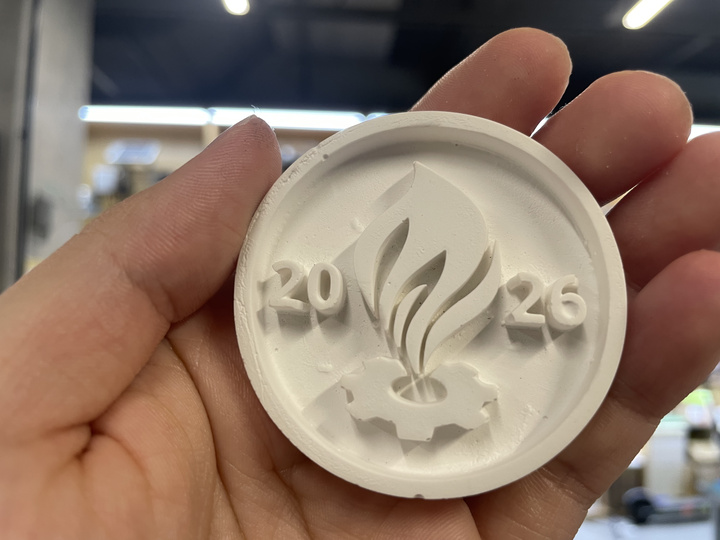
No releasing agent was used as well with this material.