Week 12-13 : Mechanical & Machine Design
Additional details beyond those presented in this document can be found in the Chaihuo's 2026 Week 12 group documentation.
Basics of mechanical & machine design
Refer to online resources for visual illustrations
-
Definition of machine :
- Mechanism : Passive parts of a system that move or transmit motion
- Actuation : Process of making parts move by applying energy or force
- Automation : Control system that manages and directs the actuatoris
- Application : The intended purpose or task the machine is designed to perform
-
Materials for machine :
- Aluminum extrusion:
- Common sizes: 20×20 mm, 30×30 mm
- Fasteners: M5, M6, M8 commonly used
- Nut types: slide-in, drop-in
- Surface: anodized or non-anodized
- Cutting: use paraffin wax to reduce friction
- Ceramic: cast or molded due to hardness
- Garolite (PCB stock): machinable structural material
- HDPE plastic: different from PLA and PETG
- Rubber / foam: damping energy
- Wood: swells with temperature and humidity
- Aluminum extrusion:
-
Adhesives (generally avoided because of difficulty to remove or separate once bonded)
- Acrylic (PMMA) : Acrylic glue
- ABS : Acetone
-
Parts :
-
Stock parts (off-the-shelf components)
- Fasteners :
- Nuts :
- Combined with bolts to tighten assemblies
- Washers are needed in vibrating systems
- Screws
- Button head screws
- Used when a clean but also visible fastener
- Flat head screws
- Aesthetic/clean surfaces or when clearance is critical (e.g. moving parts passing over)
- Lead vs ball screws
- Shoulder screw
- Only threaded at the end, s could act as pivot point.
- Button head screws
- Heat inserts :
- Inserted into plastic to create durable threads, prevents wear and stripping of the material
- Dowel pins :
- Smooth. unthreaded pins used for alignment or controlled motion
- L-brackets
- Rivets
- Couplers : used to connect shafts between components
- Nuts :
- Cable organizers :
- Cable ties
- Hook and loop fasteners (velcro straps)
- Cable carriers (drag chains)
- Fasteners :
-
Custom parts (components designed and fabricated specifically for the project)
-
-
Mechanisms:
- Note : Higher force often leads to higher friction in mechanical systems
- Joints:
- Revolute : allows rotation
- Prismatic : allows linear sliding
- Screw : converts rotation into linear motion
- Cylindrical : allows rotation + sliding
- Spherical : allows roll, pitch, and yaw
- Cams
- Linkages (series of connected joints often revolute. used to amplify or transform motion)
- Gears (transmit rotational motion, can change speed and torque)
- Rack and pinion converts rotation to linear motion
- Pulleys / belts / chains: Used for transmitting motion over distance. Chains provide strong transmission but can have uneven force variation
- Bearings : reduce friction between moving parts
- Compliant mechanisms (use flexure instead of joints)
-
Design steps :
- Define function of machine : cutting, milling, extrusion, burning, dispensing, etc
- Define performance requirements : slow and steady motion, very precise motion, etc
- Choose appropriate drive train :
- Lead screw : High force, slower motion, good precision
- Rack and pinion : Moderate speed/force
- Timing belt : Fast motion, lower precision and lightweight system
- Constraining motion/guiding system :
- Bronze bushing
- Linear rails
- Shafts
- Consider thermal stability (e.g. colling requirements) and performance
- Tool head selection
- G-code system
- Strategy :
- Inside-out : Start from internal mechanism
- Outside-in : Start from external constraints
-
Control strategies:
- Bang-bang control :
- Fully ON or fully OFF control
- Causes oscillation around target
- Can lead to wear and poor precision, not ideal for smooth or delicate systems
- Proportional-integral-derivative (PID) controller
- Linear Quadratic Regulator (LQR)
- Model predictive control (MPC)
- Bang-bang control :
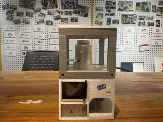
Many locations require XIAO products (such as RP2040 and ESP32-C3 modules), which motivates the development of a vending machine that is lightweight, low-cost, and easy to deploy worldwide. In addition, the system is required to be simple to operate, with efficient and user-friendly inventory management. Please refer to Emily's Week 12 documentation and Chaihuo 2026 Mechanical Design, Machine Design week for more details.
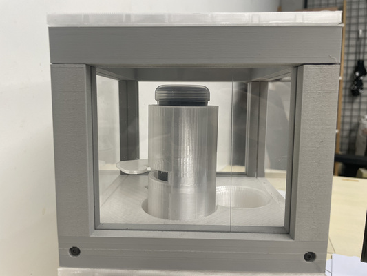
The first prototype is intentionally simple and focuses more on the lightweight, modularity and deployability of the envisioned product : users tap an RFID card to confirm their purchase, after which a servo motor is activated to smoothly dispense XIAO RP2040s or ESP32-C3s. A more refined, production-level implementation will be developed in the upcoming weeks.
Tim's involvement in the team is with the structural design and assembly, and this documentation focuses on the two design iterations, primarily driven by differences in material selection. An overview of the vending machine is shown below, with the structure divided int to main sections : the upper (grey) and the bottom (white) section.
First iteration : Aluminum extrusions
For the first iteration, the focus is on building a rough structural prototype using readily available materials, with aluminum extrusions being the primary element explored. Most of the extrusions available at the time of writing are either full-length (approximately 1 meter) or previously cut sections with uneven ends, some of which also show signs of melting (the left part of the picture) from the cutting process.
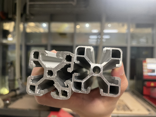
The shorter pieces were reused in the build. Despite the imperfections, it is still sufficient as a visual representation of the upper section of the vending machine.
One of the main challenges observed working with the material is the difficulty in achieving a good alignment between bolts and slot interfaces. More specific tools are perhaps needed in the future to simplify it. Although the necessary materials in general were readily available, the assembly process still took approximately two hours - given that more complex geometries are expected in the next iterations, it was concluded that 3D printing could be a more efficient alternative. Thus, only the top section was made at this stage.
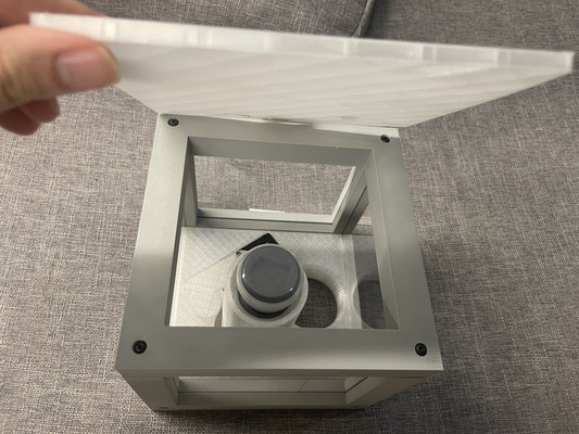
The closing lid is positioned at the top of the section to allow the XIAO boards being inserted from above. The mechanism to open and close it is also explored briefly at this stage as can be seen from the video at the right.
Second iteration : 3D-printed components
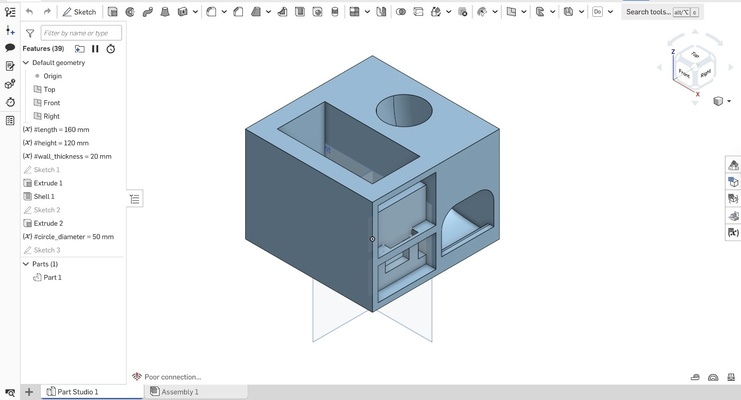
The skills developed in Week 2 : Computer Aided Design extend beyond the modelling process to include considerations for efficient 3D printing and rapid prototyping using FDM technology. By adjusting key print parameters—specifically increasing the layer height from 0.2 mm to 0.28 mm and reducing infill density from 15% to 5%—the total print time was reduced significantly from approximately 10 hours to 5 hours per section of the vending machine.
Top section
The top section is inspired by the geometry of the aluminum extrusion frame. Laser-cut acrylic panels are integrated to form a transparent shell that allows users to clearly view the components inside.
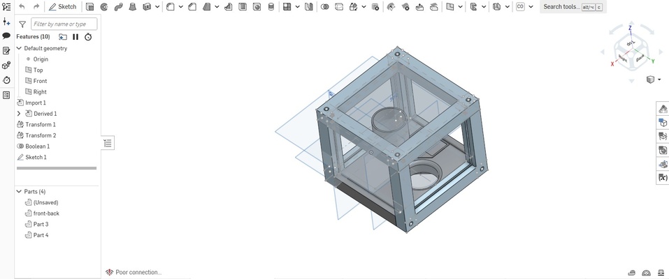
The final 3D printed results of the top section could be seen at the tab below.
M3 screws are used as the fastener between the different frame parts of the top section. Due to the reduced infill density used during printing, the components are somewhat wobbly, as there is less internal structure for the screw threads and joints to grip onto; however, the assembly still functions adequately for the prototyping purpose.
M3 screws are a standard metric fastener with a nominal diameter of 3 mm. They are widely used in electronics, prototyping, and 3D-printed assemblies because they are readily available, easy to source in different lengths, and compatible with many common threaded inserts and mounting holes used in maker and engineering projects.
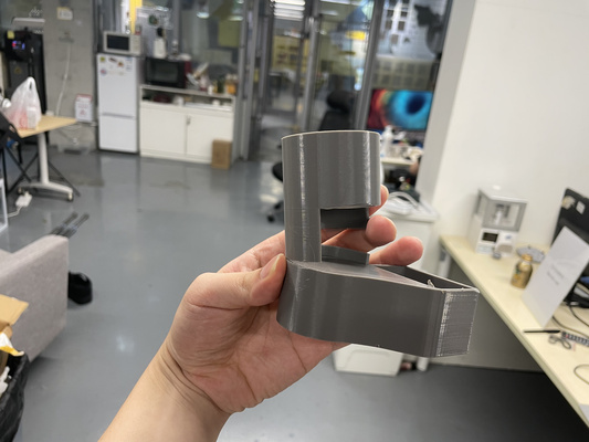
It is also worth noting out that the initial enclosure design for the XIAO boards kept on breaking (left) due to the force generated by the motor arm during contact. Chamfers (right) are therefore introduced into the design to reduce stress concentration and improve load distribution.
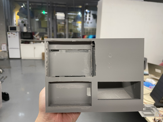
Bottom section
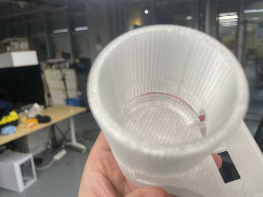
The initial design requirements for the bottom structure on the other hand are more complex, as a sliding mechanism for the XIAO MCUs, integrated cable routing features for relevant components, and mounting/other holes are needed.
The first version unfortunately had several limitations :
- Lacks proper fit with the components
- Restrictive opening for hand access to retrieve XIAO boards via the slide
- Mounting holes were not included at this design
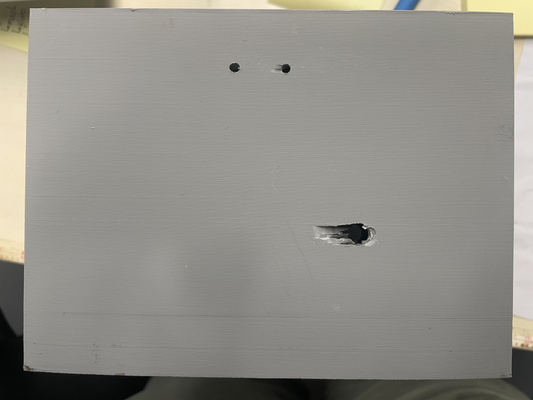
Therefore, adjustments were required using a small rotary cutting tool to enlarge the opening and improve the fit (left), allowing a clearer understanding of the required clearance and overall spacing between components. In addition, the mounting holes (right) had to be drilled manually; however, it was quickly realised that it is more effective to incorporate these features directly into the 3D print, as the low infill setting results in reduced internal strength and poor material grip.
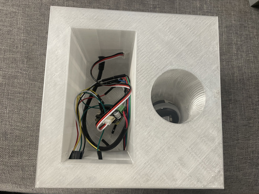
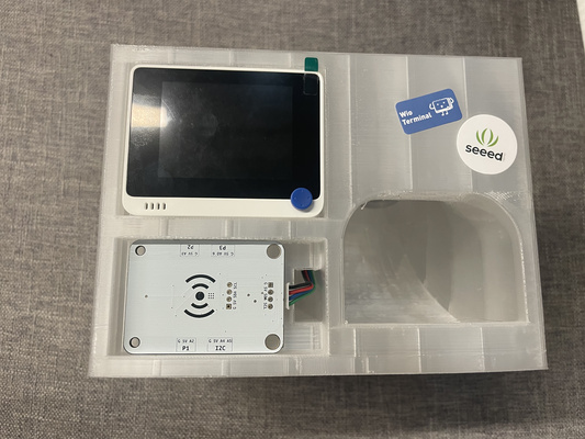
The final 3D printed results of the bottom section could be seen at the tab below.
Files
- Top section :
- Bottom section :