General log
Cursor (an AI assistant) was used throughout this log as a research and writing aid — to explain technical concepts, summarise reference material, clarify questions, and help structure and draft the documentation. All explanations were reviewed, tested against the actual build where possible, and verified by the author.
Week 1 : Preliminary concept sketch
Problem :
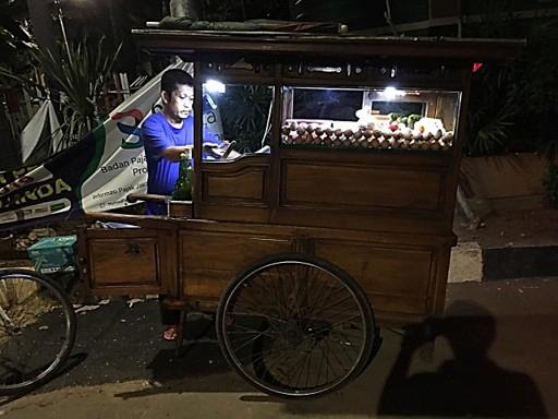
Mobile street vending is widespread globally, yet many lack reliable (and safe) access to affordable electricity especially during evening and night-time trading hours
Target user characteristics :
- Trade mostly in the evening
- Daily-based income
- Limited technical knowledge
Solution :
Plug and play, pay-as-you-go (pay amount based on usage or time for example daily, weekly or monthly) solar PV system for essential lighting and load appliances of the street, inspired by implementation in Africa.
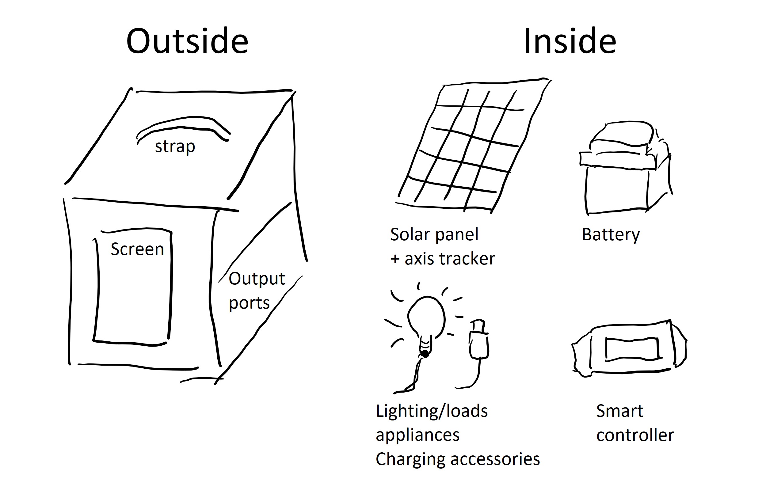
Main features :
- Solar panel with built-in axis tracker for optimal energy capture in the morning before use during night-time trading hours.
- Smart controller that enables flexible installment payments (pay-as-you-go) without upfront cost and embedded security features.
Week 2 : Consultation at SEEED studio
First consultation on the final project with Matthew, the Fab Academy 2026 instructor for ChaiHuo makerspace, was done at the SEEED studio (check out @timmili_makers week 2 to get a peek)!
The following topics were discussed :
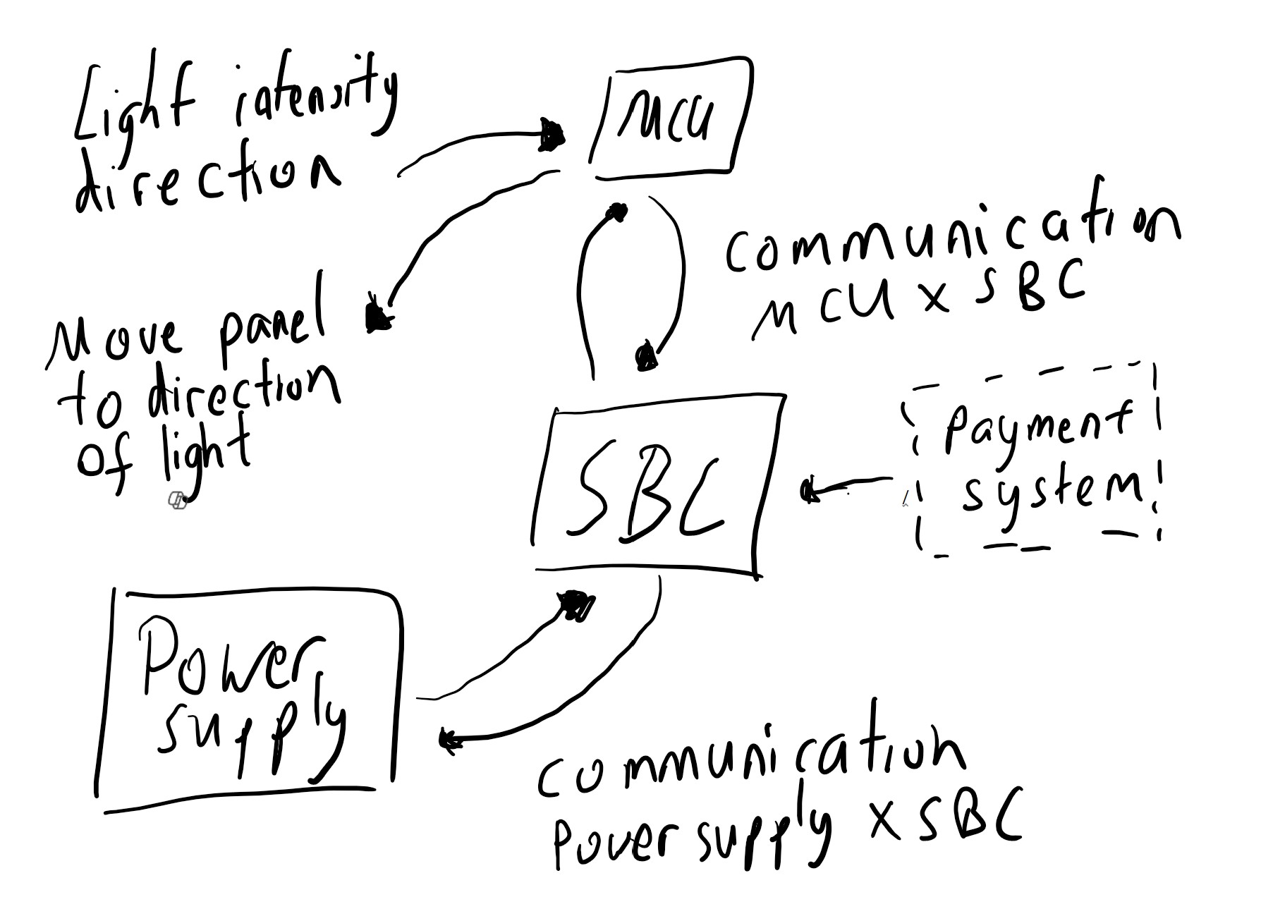
- Work breakdown ; the following upcoming sections will be organized around these four main building blocks: SBC, MCU, power supply, and payment system (see respective logs for detailed research)
- Focus will be on building a small, simple prototype first, with further expansion planned after gaining insights from the initial
- Materials required for the first prototype
Updates :
- MCU + peripherals: -
- SBC : -
- Power supply : -
- Payment system : -
Week 3 : Components acquired, initiate prototype testing
The following components were sourced from Taobao. Specifications on it could be seen below :
| Component | Specifications / Notes | Quantity | Additional Details |
|---|---|---|---|
| Photoresistor | Light-dependent resistor, Vin : 3.3~5.5 V | 1 | Detects light intensity |
| Servo motor | Vin : 4.8–6 V | 1 | Used to adjust solar panel orientation |
| Solar Panel | Voc : 9 V, Isc : 1.23 A, 220 x 340 x 3 mm | 1 | Converts sunlight to electrical energy to charge battery |
| Solar voltage Regulator | Vin : 9-30 V, Output (V A): 5 V 3 A, 9 V 2 A, 12 V 1.5 V | 1 | Stabilizes voltage for MCU and sensors |
| Battery | Vout: 5V, Iout : 2.5~3A, Li-ion, 6800 mAh | 1 | Powers the system despite when sunlight is low |
Regarding Voc and Isc
-
VOC (Open-Circuit Voltage):
This is the maximum voltage the solar panel can produce when no current is drawn (open circuit). It represents the upper voltage limit of the panel. -
ISC (Short-Circuit Current):
This is the maximum current the solar panel can produce when the terminals are shorted together (voltage = 0). It represents the highest current the panel can deliver under full sunlight. It is used to size fuses, wires, and regulators safely.
Source: ChatGPT by OpenAI, February 2026
Decision is also made for the payment system for a remote activation path that is to a certain extent inspired by the OpenPAYGO's concept.
Updates :
- MCU + peripherals : -
- SBC : -
- Power supply : -
- Payment system : Remote activation payment
Week 4 : MCU, servo motor, and light direction testing
The components purchased during Week 3 were used as the basis for the initial benchmarking experiments. This week focuses on comparing different motor types and light-sensitive sensors in order to better evaluate the suitability of the selected components for the intended final project application. In addition, the interface of these components with the MCU is also tested to verify integration and communication.
Lessons learned : All components and the microcontroller must share the same reference point (common ground)
Updates :
- MCU + peripherals :
- Comparison of motors and light-sensitive sensors
- The connection and communication between the XIAO ESP32C3 MCU, servo motor and two light direction systems were tested. Test results could be seen at the Week 4 : Embedded Programming documentation.
- SBC : -
- Power supply : -
- Payment system : -
Week 5 : Solar charging path revision
Compact size and low weight are prioritised over the solar panel's ability to fully charge the battery within a single day. The focus this week is therefore to validate the chain from the solar panel to the battery charging system to ensure that it operates correctly and behaves reliably under real-world conditions. During outdoor testing, some technical issues were identified specifically on the compatibility between the solar regulator and solar panel, as well as the battery management system (BMS) of the purchased battery pack.
| Component | Specifications / Notes | Quantity | Additional Details |
|---|---|---|---|
| Photoresistor | Light-dependent resistor, Vin : 3.3~5.5 V | 1 | Detects light intensity |
| Servo motor | 4.8–6 V, stall torque ≈ 5.5 kg·cm (4.8 V) / 6.5 kg·cm (6 V) | 2 | Used to adjust solar panel orientation |
| Solar Panel | Voc : 9 V, Isc : 1.23 A, 220 x 340 x 3 mm | 1 | Converts sunlight to electrical energy to charge battery |
| Solar Regulator (Replaced) | Vin : DC 5–36 V, Vout : 5 V, Iout : 2-3 A | 1 | Stabilizes voltage for MCU and sensors |
| Battery Pack (Replaced) | Vin, Iin : 5 V, 2 A, Vout, I out : 5V 5A, pass through/UPS | 1 | Powers the system despite when sunlight is low |
Updates :
- MCU + peripherals :
- SBC : -
- Power supply : Revision on solar regulator and battery pack
- Payment system : -
Week 6 : First PCB design
A first revision was designed that integrates four phototransistor channels and two SG5010 servo outputs - result could be seen at Week 6 : Electronics Design. It is worth to note that the power for the system comes from a bench DC supply and 5 V for the servos is taken from the XIAO RP2040's 5 V pin.
Improvements to be made :
- Replacing the bench supply with a battery-based power path so that it matches expected deployment scenario
- Route servo motor current on a dedicated 5 V rail as the RP2040 potentially could not provide sufficient amps
At this stage, the design does not yet incorporate additional resistor networks. Therefore, a more in-depth investigation was conducted to better understand how they could be integrated into future revisions of the system.
Understanding resistors and the pull-up and pull-down concept is also explored this week.
Updates :
- MCU + peripherals : Deep dive on resistors
- SBC : -
- Power supply : -
- Payment system : -
Week 7 : MOSFET switching for remote power control
The next focus is to better understand MOSFET-based switching circuits to enable remote control on power management of the solar pv system.
Updates :
- MCU + peripherals : -
- SBC : -
- Power supply : Deep dive on MOSFETS
- Payment system : -
Week 8 : Capacitors for power stabilisation
The next focus is to better understand capacitor behavior to stabilise the power management of the solar PV system.
Updates :
- MCU + peripherals : -
- SBC : -
- Power supply : Deep dive on capacitors
- Payment system : -
Week 9 : Localisation, orientation, and timekeeping inputs
Input devices that are relevant to the final project specifically on location and orientation are explored further. GPS reception was also already documented at Week 9 : Input Devices and therefore the focus here to understand the working mechanism of namely compass, GPS and RTC.
Updates :
- MCU + peripherals : Deep dive on compass, GPS and RTC
- SBC : -
- Power supply : -
- Payment system : -
Week 10 : Servo motor load test
The servo motor forms the core of the solar-tracking mechanism. To assess the mechanical requirements of the system, the mass of the moving components was measured and found to be:
Solar panel with laser-cut back panel: 350 g Servo motor (each): 50 g
An initial load test was conducted using the SG5010 servo without performing a detailed load or torque analysis beforehand. The purpose of this test was to evaluate the feasibility of the proposed design and identify any mechanical limitations.
"Structure" is added at the updates block.
Updates :
- MCU + peripherals :
- SBC : -
- Power supply : -
- Payment system : -
- Mechanical structure : SG5010 x solar panel stress test
Week 11 : Server and remote device communication
Wireless communication channel between a server and a remote device is tested. This link forms a key part of the system architecture and is intended to carry lock/unlock control commands that is relevant to the payment system.
This builds upon the work already done on Week 11 : Networking & Communications that used 2 XIAO ESP32C3 to communicate with each other through LoRA. Test on the Raspberry Pi as a server is initiated.
Updates :
- MCU + peripherals : -
- SBC : Raspberry Pi set up to publish MQTT commands through LoRA
- Power supply : -
- Payment system : -
Week 12-13 : Main structure fabrication and testing
Following up the progress and lessons learned from week 10, the mast structure is now designed in 3D CAD and fabricated. A further servo test was carried out this week, this time with the stronger MG996R. The mechanism to raise the tower is also explored in which the panel could be elevated and lowered for storage i.e. extendable.
The updated main components are listed below.
| Component | Specifications / Notes | Quantity | Additional Details |
|---|---|---|---|
| Photoresistor | Light-dependent resistor, Vin : 3.3–5.5 V | 1 | Detects light intensity |
| Servo motor (replaced) | Vin : 3–7.2 V, stall torque ≈ 13 kg·cm, ≈ 55 g, 180° rotation (replaces the SG5010 for more torque) | 2 | Adjusts the solar-panel orientation |
| Solar panel | Voc : 9 V, Isc : 1.23 A, 220 × 340 × 3 mm | 1 | Converts sunlight to electrical energy to charge the battery |
| Solar regulator | Vin : DC 5–36 V, Vout : 5 V, Iout : 2–3 A | 1 | Stabilises voltage for the MCU and sensors |
| Battery pack | In : 5 V 2 A, Out : 5 V 5 A, pass-through / UPS | 1 | Powers the system when sunlight is low |
Updates :
- MCU + peripherals : -
- SBC : -
- Power supply : -
- Payment system : -
- Mechanical structure :
- Tracker head + mast design and fabrication
- Extendable mechanism
- MG996R x solar panel load test
Week 14 : PCB design (incl. power distribution) and fabrication
The project’s custom PCB was designed with the appropriate power rail and fabricated using CNC milling as an initial validation step to ensure the system functions as intended. The board integrates the microcontroller unit (MCU) and the load-switching circuitry responsible for controlling the lock mechanism.
An attempt was also made to use crimped connectors to improve the mechanical robustness of the assembly. However, the results were not satisfactory due to poor crimp quality, and this approach was ultimately discarded in favour of using pre-made connectors instead. Please refer to the MCU + peripherals log for more information.
Updates :
- MCU + peripherals : PCB design and fabrication
- SBC : -
- Power supply : Power system architecture
- Payment system : -
- Structure : -
Week 15 : Control-loop and lock test
With the custom PCB completed and the web interface prepared, the end-to-end system architecture was ready for testing. This allowed verification of communication between the server, wireless link, and remote device. Real payment system (i.e. not just turn on and off command) is also explored.
Updates :
- MCU + peripherals : System architecture test
- SBC : Refer to Week 15 : Interface & Application Programming for details
- Power supply : -
- Payment system : Payment system integration
- Structure : -
Week 16 : Control unit design and fabrication
The housing brings the electronics together and so much effort went into the placement of these components (e.g. sensors, switches, cables, etc). User interaction is considered to ensure that each part is accessible and correctly oriented as part of the design. Its fabrication is also conducted this week.
Further details could be seen at Week 16 : System Integration
Updates :
- MCU + peripherals : -
- SBC : -
- Power supply : -
- Payment system : -
- Structure : Enclosure design and fabrication
Week 17 : Logo casting
The enclosure incorporates a dedicated recess for a cast fluorescent logo. The logo serves as a visual identifier while enhancing the overall appearance of the product, helping to break up what would otherwise be large, featureless surfaces. The fluorescent material also is thought to be able to improve visibility under low-light conditions, providing a subtle visual accent without requiring additional LEDs or electrical power. Several observations and lessons learnt were gathered during the process.
Updates :
- MCU + peripherals : -
- SBC : -
- Power supply : -
- Payment system : -
- Structure : Logo casting + deep-dive fluorescent
Week 18 : Assembly & BOM
By this stage all the parts were in place (fabricated or bought), so the week focused on assembly — bringing the building blocks together into the working unit. Week 18 : Project Development, Applications & Implications outlines the BOM - planned and actual - and cost analysis, evaluation criteria and next iteration notes of this project.
Updates :
- MCU + peripherals : -
- SBC : -
- Power supply : -
- Payment system : -
- Structure : -
Week 19 : Final assembly
Assembly carried on toward the finished unit. Full licensing details on the project is also listed at Week 19 : Invention, Intellectual Property, and Income page. Updates :
- MCU + peripherals : -
- SBC : -
- Power supply : -
- Payment system : -
- Structure : -
Week 20 : Showtime!
The final presentation week — everything is brought together into the final project presentation (summary slide and one-minute video). See the Final project : Overview tab for the full summary of the project's conception, construction, and operation!