Week 9 : Input Devices
PCB CNC milling not available at time of writing at the workspace. Thus, tests were mainly done on breadboard. The final result-with the CNC milling- could be seen further below
Week 9 assignment could be categorized as follows:
-
Group assignment
- Input devices signal characteristics
-
Individual assignment
- Sensor + designed PCB test
Additional details beyond those presented in this document can be found in Chaihuo's 2026 Week 9 group documentation.
Input devices signal characteristics
Types of input sensors
- Air quality
- Detects dust/particles
- Distance
- Measures distance to objects
- Encoder
- Measures rotation or linear movement. Counting pulses = tells position. Pulse frequency = tells speed.
- Force
- Measures applied force or pressure
- Image/vision
- Captures images and processes them digitally
- Light
- Phototransistor: Changes current based on light intensity
- Photoresistor: Changes resistance based on light intensity
- Color: Detects RGB light components
- Magnetic field vector
- Measures magnetic field X, Y, Z axes
- Magnetic switch/hall
- Measures magnetic field strength and detects change
- Motion
- Pyroelectric (obsolete): Detects human body heat movement
- Doppler/LIDAR: Detects motion via frequency shift
- Motion & Orientation/IMU (Inertial Measurement Unit)
- Acceleration (XYZ)
- Rotation (Gyroscope)
- Magnetic field
- 6-axis = acceleration + rotation, 9-axis = acceleration + rotation + magnetic field
- Sound
- Converts sound waves into electrical signals
- Temperature
- Typical use: Monitor and control temperature
- Time & location
- Real-time clock (RTC): Tracks time
- GPS: Location and time (Needs satellite visibility)
- Vibration
- Measures mechanical oscillations or shake
Sensors must be interfaced with a microcontroller to provide meaningful data. This interface depends on the type of signal the sensor produces (analog/digital) and the processing method of it. These input methods could be categorized as the following :
- Direct input methods (microcontroller reads signal from sensor itself):
- GPIO (ports)
- Comparator : Threshold-based detection. Not available at XIAO RP2040 and XIAO ESP32C3.
- ADC
- Communication interfaces (microcontroller reads data from another chip):
- I2C
- SPI
- UART
The SEEED Studio Grove system is a modular electronics platform designed to simplify prototyping with a wide range of sensors and microcontrollers. It uses standardized 4-pin connectors, allowing components to be easily connected without soldering and detailed documentation - including usage guide and example code - is available on the SEEED studio wiki. At the time of writing this documentation, there are 20 Grove sensors that are available at Chaihuo makerspace and 13 of them managed to be tested.
4-pin connectors have a housing that mechanically prevents incorrect orientation or misalignment
Note : This test is aimed to understand the characteristic of the (digital and analog) signal and the the physical connections (i.e. I2C and UART) between the Grove sensors and the XIAO ESP32C3. Detailed investigation on the underlying principals of all sensors were not conducted and communication interfaces characteristics will be explored further in the coming weeks. With this in mind, the Arduino IDE was used as the programming environment - usage and setup could be found at the Week 4 : Embedded Programming documentation.
| Sensor Name | Interface | Additional notes |
|---|---|---|
| Grove - Air Quality Sensor | Analog | ⚠️ results though are inconclusive. Need to be compared with real dataset |
| Grove - Encoder | Digital | - |
| Grove - GPS | UART | - |
| Grove - Light Sensor | Analog | - |
| Grove Mech Keycap | Digital | - |
| Grove - PIR Motion Sensor | Digital | - |
| Grove - RTC (Real-Time Clock) | I2C | Without battery, only powered through USB |
| Grove - Rotary Angle Sensor | Analog | - |
| Grove - Temperature Sensor | Analog | ⚠️ worked, further test could be done to test extremes/sensitivity |
| Grove - Thumb Joystick | Analog | ⚠️ worked, results though are inconclusive. Need to be tested with moving parts |
| Grove - Touch Sensor | Digital | - |
| Grove - Loudness Sensor | Analog | - |
| Sensor Name | Interface | Additional notes |
|---|---|---|
| Grove - 3-Axis Digital Accelerometer | I2C | - |
| Grove - 6-Axis Accelerometer & Compass | I2C | - |
| Grove - 6-Axis Accelerometer & Gyroscope | I2C | - |
| Grove - Gas Sensor | Analog | - |
| Grove - High Precision Barometer Sensor (DPS310) | I2C | - |
| Grove - IMU 10DOF | I2C | ⚠️ tested, but results though are inconclusive. Need to be tested with moving parts. Flagged as not yet tested |
| Grove - Line Finder | Analog | - |
| Grove - Moisture Sensor | Analog | - |
Most of the reference implementations at the wiki are based on Arduino board and might require adjustments to make it actually work. AI in this case could help greatly with the process.
The following sections therefore highlight cases where additional configuration, debugging, or modifications were needed beyond straightforward plug-and-play usage. Incidentally, these examples also cover a range of communication interfaces, including UART, I2C, as well as digital and analog connections.
While the Grove board is convenient for quick prototyping, it may introduce slight additional resistance and contact impedance due to its connectors (e.g. LED was spotted to be dimmer than with breadboard during the test). In such cases, testing on a breadboard with direct jumper wire connections could be an alternative. The breadboard though is also not reliable especially for long-term setups
Limitations of breadboards
-
Component limitations: Breadboards are designed for through-hole components. This means users need to have through-hole and SMD components in their inventory.
-
Poor electrical performance: The internal connections can introduce noise, resistance, and crosstalk between signals, which may affect circuit behavior—especially for high-speed or sensitive signals.
-
Mechanical instability: Connections are not secure. Moving or handling the breadboard can loosen wires or components, causing the circuit to stop worrking and so lack of reliability.
Rotary angle vs Encoder | Digital vs Analog
Both the encoder and the rotary angle sensor are used to measure rotational movement. Differences in working principle could be seen at the table below.
| Feature | Rotary Angle Sensor | Encoder |
|---|---|---|
| Signal Type | Analog | Digital |
| Output Type | Absolute position (angle) | Relative movement (steps) |
| Measurement Range | Limited (e.g., ~300°) | Continuous rotation |
| Precision | Limited by ADC resolution | Higher (depends on encoder resolution) |
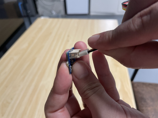
A rotary encoder generates digital pulses as it rotates. These pulses come from two signals, CLK (Clock) and DT (Data), and the relative timing between them allows the system to determine the direction of rotation—clockwise (CW) or counterclockwise (CCW). By counting the number of pulses, the system can evaluate how far the encoder has been turned. For a clearer visual explanation, please refer to resources online.
In contrast, a rotary angle sensor produces an analog voltage proportional to its rotational position. This allows it to directly indicate the absolute angle of the knob. The analog output can be read via an ADC pin and mapped to control outputs, such as LED brightness. Unlike the encoder, the rotary angle sensor does not inherently detect direction; it simply reports the current position.
GPS | UART
The Grove GPS module communicates using UART and can be interfaced directly with the XIAO ESP32C3 without requiring additional softwares (at the time of writing this document, the wiki mentioned the SIMCom GPS DEMO). The module outputs standard NMEA sentences (standardized text message format used by GPS modules to transmit data such as location, time, speed and satellite information), which can be parsed (i.e. converted to more readable text) using libraries like TinyGPS++.
Two key conditions must be ensured for the GPS module to function correctly: - The module communicates via UART, which means the GPS module’s TX should be connected to the XIAO’s RX, and the GPS module’s RX to the XIAO’s TX. - The GPS requires an open outdoor environment to acquire satellite signals
The module should pick up signals within 2 minutes. If this is not the case, then it is likely that one or both of these conditions have not been met.
The working GPS code could be seen at the admonition below.
GPS x XIAO ESP32C3 code
#include <TinyGPS++.h>
#include <HardwareSerial.h>

TinyGPSPlus gps;
HardwareSerial GPSSerial(1); // UART1 for GPS

void setup() {
  Serial.begin(9600); // USB serial monitor
  while (!Serial);

  Serial.println("Starting Grove GPS Debug...");

  // RX = GPIO20, TX = GPIO21
  GPSSerial.begin(9600, SERIAL_8N1, 20, 21);

  Serial.println("Waiting for GPS data...");
}

void loop() {
  while (GPSSerial.available()) {
    gps.encode(GPSSerial.read());
  }

  if (gps.charsProcessed() < 10) {
    Serial.println("No GPS data yet...");
    delay(1000);
    return;
  }

  Serial.print("Satellites in view: ");
  Serial.println(gps.satellites.value());

  if (gps.location.isValid()) {
    Serial.print("Latitude: ");
    Serial.println(gps.location.lat(), 6);
    Serial.print("Longitude: ");
    Serial.println(gps.location.lng(), 6);
  } else {
    Serial.println("Waiting for GPS fix...");
  }

  delay(1000);
  }

  *Source: ChatGPT by OpenAI, March 2026*
The figures below shows the location of the outdoor experiment to test the definition of "open environment". Although it is in between walls, it was still able to acquire satellite signals. In this case, 4 satellites.
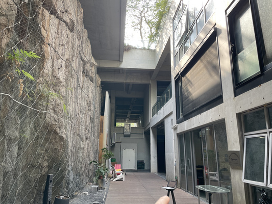
A second test was then carried out to compare indoor performance. When the device was moved indoors, the number of detected satellites dropped significantly (i.e. from 4 to 0 satellites). This clearly highlights the strong dependency of the GPS signal quality on the environmental conditions.
RTC | I2C
RTC is used to keep track of time. Although microcontrollers might include internal RTCs, the external ones generally provide higher accuracy. Furthermore, external power supply (e.g. battery) enables the module to keep time even when the main power supply - that might power other components - is lost.
The component uses the I2C protocol and so uses two signal line :
- SDA (serial data) : carries data
- SCL (series clock) : provides timing
In order for the module to work, the following conditions need to be met : - Correct wiring. SDA of microcontroller needs to be connected to the SDA of the module. This also applies to SCL. - The I2C needs to be initialized in the code (i.e. Wire.begin()) otherwise no communication will occur.
Sometimes the serial monitor needs also to be closed and reopened to re-establish connection. Behaviors vary across OS, IDEs, etc
The working RTC code could be seen at the admonition below.
RTC x XIAO ESP32C3 code
#include <Wire.h>
#include "RTClib.h"

RTC_DS1307 rtc;       // RTC object
const int ledPin = 3; // LED on GPIO3

void setup() {
Serial.begin(9600);
delay(1000);

pinMode(ledPin, OUTPUT);

Wire.begin(6, 7); // SDA=6, SCL=7 (your working pins)

if (!rtc.begin()) {
    Serial.println("Couldn't find RTC!");
    while (1);
}

Serial.println("RTC found!");

rtc.adjust(DateTime(2026, 3, 21, 15, 54, 0));
}

void loop() {
DateTime now = rtc.now();

int sec = now.second();

// LED logic: ON if seconds do NOT contain digit 3
if ((sec % 10 != 3) && (sec / 10 != 3)) {
    digitalWrite(ledPin, HIGH);
} else {
    digitalWrite(ledPin, LOW);
}

// Print current time to Serial Monitor
Serial.print(now.hour()); Serial.print(":");
Serial.print(now.minute()); Serial.print(":");
Serial.println(now.second());

delay(1000);
}
Note :The LED used in this example is not essential for verifying I2C communication. It is included only as a simple visual indicator to show that the program is running and reacting to data from the RTC. The behaviour of the LED is not directly connected to or representative of the I2C signals.
Sensor + designed PCB test
The final project requires a reliable and sensitive light sensing mechanism. For this reason, a comparison between a photoresistor and a phototransistor was carried out, with more detailed observations documented in the MCU + peripherals log under the Final Project tab. In general, the phototransistor behaves as a light-controlled transistor, meaning that incident light generates a current which is then amplified internally. Therefore, this amplification character boosts the sensitivity of the component. High absolute measurement accuracy is not a strict requirement as two phototransistors are used to measure relative differences in light intensity. The consistency and responsiveness of the sensor is thus more important.
The industrially manufactured PCB is used for the test - however it was not designed to include a display (this will be added next week) and so a "visual aid" is needed to understand the sensor's behaviour apart from the serial monitor. Therefore the servo motor is used for this, which is also part of the final project.
It can be observed that the servo motor rotates in response to changes in light detected by the phototransistor.
The bill of materials (BOM) is listed below :
| Qty | Component | Description |
|---|---|---|
| 2 | Photoretransistor | Light sensor |
| 2 | Pin sockets | For interface between PCB and phototransistor |
| 1 | Pin headers | For interface between PCB and servo |
| 1 | Seeed Studio XIAO RP2040 | Microcontroller for reading sensor and controlling servo |
| 1 | Servo motor (e.g. SG5010) | Visual output device to indicate light level |