Week 16 : System Integration
This week focused on the design and documentation planning for the final project. At this stage, the project concept had been finalized as a single-axis east–west solar panel tracker. The system also incorporates a mechanism that temporarily locks it if the subscription (dummy) payment is not made on time.
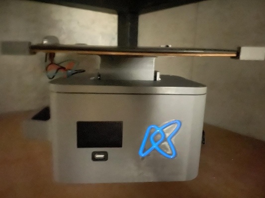
The images below show the final product for context. The one on the right depicts the system at "night mode".
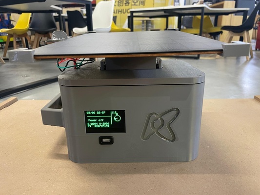
The product is organised into two physical assemblies connected by a mast, and four functional building blocks distributed across them :
- Physical assemblies :
- Tracker head — the solar panel module mounted at the top of the mast, carrying the single-axis east–west tracking mechanism and the phototransistors
- Control unit — the base enclosure that houses the energy storage, the payment/lock logic, etc
- Functional building blocks
- Power supply — solar panel → solar regulator → UPS-style battery pack, with MOSFET-based load switching (see power supply log).
- MCU — the embedded controller (XIAO ESP32-C3 / ESP32 DevKit) that drives the servo tracking, reads the light sensors, and enforces the paid/locked state (see MCU log).
- SBC — the Raspberry Pi acting as the local server hosting Node-RED and the MQTT broker (see SBC log).
- Payment system — the token-based pay-as-you-go logic that gates the load, validated either offline (OpenPAYGO-style token) or remotely through the Week 15 stack (see payment system log).
The firmware part has already been extensively covered at Week 15 : Interface & Application Programming and is therefore only mentioned here as a reference.
The next sections discusses the electrical and mechanical integration of the project.
Electrical integration
The diagram below shows the power flow and the load switch control. The MCU is powered straight from the battery and keeps running at all times while the MOSFET gates the servo and the user load.
flowchart TB
  PANEL["Solar panel
 VOC 9 V, ISC 1.23 A"] -->|~9 V| REG["Solar regulator
 5–36 V in to 5 V out"]
  REG -->|5 V| BATT[("Battery
 holds the 5 V rail steady")]

  BATT ==>|5 V rail · always on| MCU["MCU (on PCB)
 always running"]
  BATT ==>|5 V rail| SW{{"MOSFET load switch
 (on PCB)"}}
  MCU -->|gate drive/signal input| SW

  SW -->|switched 5 V| SERVO["Servo
 E–W tracking"]
  SW -->|switched 5 V| LOAD["User load
 (for the protoype focus only on phone charging)"]

  MCU <-.->|MQTT over LoRA| SBC["SBC server
 (separate remote system)"]
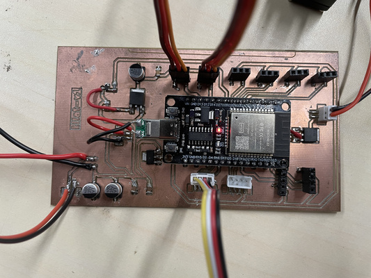
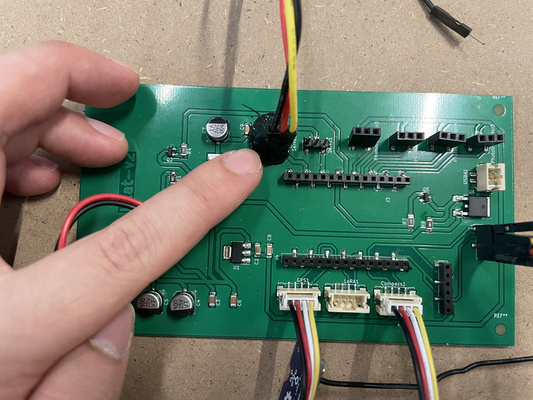
The milled PCB used for testing is shown below for illustration purpose. The cleaned and finalized version could be seen at the next section.
Signal path
An overview of the signal path are as follows :
- Local control loop (MCU) : reads the light-direction sensor array (analog), drives the servo (PWM ~50 Hz) to keep the panel aligned east–west
- Lock control (MCU → MOSFET) : the MCU drives the gate of the MOSFET load switch to enable or disable the user load based on the current paid/locked state.
- Remote path (MCU ↔ SBC ↔ cloud) : the MCU exchanges commands and telemetry with the Raspberry Pi over MQTT (LoRA), and the Pi bridges to the remote Vercel interface through the Cloudflare tunnel.
Mechanical integration & packaging
The packaging strategy mirrors a commonly used solar home system with the main components integrated in a compact and robust enclosure. The primary distinction is the inclusion of a mast that could be manually elevated to ensure that the solar panel have enough room for tracking movement.
It is important to note that the solar panel is by far the largest component in the system and therefore largely dictates the overall dimensions of the product. The control unit is proportioned around the panel, with its overall height determined by the panel's longer dimension, while its width is driven by the space required to accommodate the remaining internal components.
This arrangement allows the product to be stored in either a vertical or horizontal orientation, offering greater flexibility given that available space may be limited.
Generous amount of chamfers will be applied throughout the mechanical parts to remove sharp corners.
-
Tracker head
- Mounts the solar panel to the servo output via a bracket, with rubber grommets/bushings to isolate vibration and distribute clamping force on the thin servo ears (as researched in the MCU log).
- Carries the light-direction sensor array positioned so the two channels see a balanced field of view for east–west comparison. The cable carrying the signals down to the control unit is planned to be inserted inside a cable skeleton (a flexible segmented cable sleeve/spine) so that it is protected and never left exposed.
-
Control unit
- Houses the battery pack and PCB
- Exposes the user-facing interfaces: power/slide switch, OLED status display, the load output, etc
- Acts as the structural base/foot of the mast so the device is stable
-
Mast
- Raises the panel above the control unit and routes the panel, servo, and sensor wiring internally, so that none of the cabling is visible from the outside.
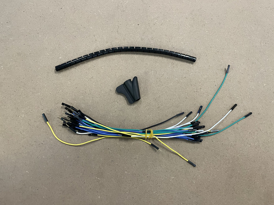
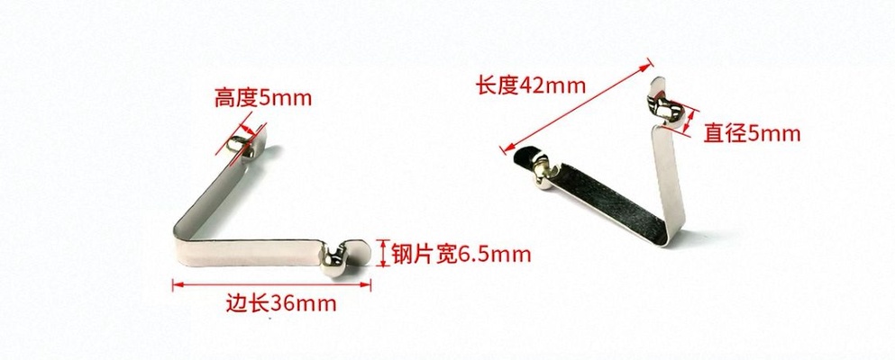
- A spring detent button of the type shown below is planned. The rounded spring heads snap out through holes in the tube to lock a section in place, and are pressed inward to release it and collapse the mast.
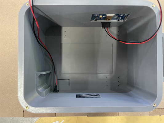
Component mounting strategy
The way each electrical component is held in the control unit depends on whether it provides its own fixing points - parts that already have mounting holes (the PCB, the Raspberry Pi, the servo) get matching drilled/screw holesin the case so they can be bolted down, while parts without mounting holes (such as the battery pack) are instead retained by slot or captive joints designed into the case so they cannot shift.
Heat-set threaded inserts
Most components are expected to be manufactured using FDM 3D printing in either PLA or PETG. The exception is the back panel, which will be laser-cut due to the size limitations of the available 3D printer build plate at the time of writing. Furthermore, brass heat-set threaded inserts will be embedded into the 3D printed parts to improve the grip between the components. Some lessons learned during the assembly process of this particular step is documented at the admonition below.
Heat-Set Threaded Inserts hole parameter and assembly technique
-
Insert vs. screw definition of outer diameter : A heat-set insert is a small brass sleeve with a pre-formed M3 internal thread for the screw and a larger knurled outer body that anchors the insert within the plastic. The insert's outer diameter is typically 4.0–4.6 mm, which is why the printed hole must be significantly larger than the 3 mm screw diameter.
-
Hole size: The printed hole should be slightly smaller than the insert's outer diameter to create an interference fit. As the insert is heated and pressed into place, the surrounding plastic flows into the knurled surface and locks the insert in position. For most M3 heat-set inserts, a hole diameter of approximately 4.0 mm in PLA and 4.1–4.2 mm in PETG is a good starting point. A hole that is too small will displace a large volume of softened plastic that accomulates around the insert and obstruct the threaded bore. It is recommended to make it slightly deeper than the insert length that creates a relief pocket.
-
Installation temperature: PLA and PETG soften at different temperatures, so the soldering iron used for installation should typically be set 10–20 °C above the material's printing temperature. As a general guideline, 220–230 °C works well for PLA, while 240–250 °C is suitable for PETG.
Source: Cursor by Anthropic, May 2026
Wiring and connectors
To keep the sub-systems modular and serviceable, the connections primarily rely on JST connectors together with pin sockets and headers rather than permanently soldered wires. The PCB is expected to be mounted flat at the base of the control unit (see the Mechanical Integration & Packaging section for additional illustrations), and the use of 22 AWG cable throughout the system helps simplify component selection while increasing mechanical robustness.
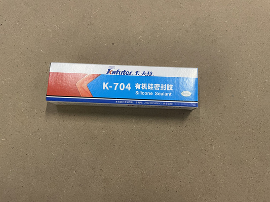
Silicone electronic adhesive is also intended to be applied over non-JST connections to improve their mechanical stability.
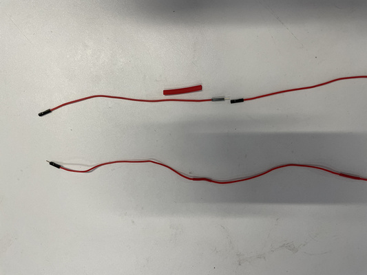
For the longer cable runs — in particular the panel, servo, and sensor wiring that travels up the mast to the tracker head — heat-shrink tubing is used to bundle and insulate the conductors.
The picture below shows the before and after of extending the cable with the heat-tube wrapping.
Other : Logo cast
A logo cast using the the technique explored in Week 14 : Molding & Casting is used to create a glowing fluorescent accent with the hardness of crystal epoxy to eliminate the need to add additional LEDs to the system.
The result can be seen in the night mode section at the beginning of this documentation.