Details : Power supply
Cursor (an AI assistant) was used throughout this log as a research and writing aid — to explain technical concepts, summarise reference material, clarify questions, and help structure and draft the documentation. All explanations were reviewed, tested against the actual build where possible, and verified by the author.
Week 1
-
Week 2
-
Week 3
-
Week 4
-
Week 5
Regulator x 9 V solar panel
The previously purchased buck regulator requires a minimum input voltage of 9 V, while a 9 V Voc solar panel typically delivers a lower voltage under normal operating conditions.
This behaviour was also observed experimentally: the charging indicator LED on the solar regulator rarely illuminated, suggesting that the regulator was seldom operating within its required input voltage range.
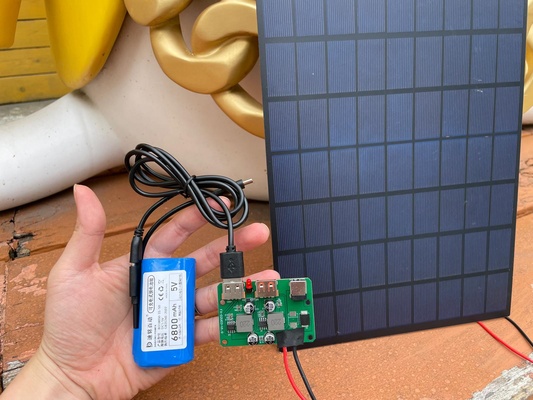
As a result, it must be replaced with the component that supports a wider input range, specifically from 5 V to 36 V.
Low dropout linear regulator (LDO) vs buck
Both produce a lower regulated voltage from a higher input, but they get there in completely different ways
-
LDO (linear) : behaves like a smart variable resistor. It "throws away" the extra voltage by turning it into heat. $$ P_{heat} \approx (V_{in} - V_{out}) \times I $$ Example : with \(V_{in} = 9\ \text{V}\), \(V_{out} = 3.3\ \text{V}\), \(I = 0.2\ \text{A}\) : $$ V_{drop} = 9 - 3.3 = 5.7\ \text{V} \quad\Rightarrow\quad P_{heat} \approx 5.7 \times 0.2 = 1.14\ \text{W} $$ At a smaller load current \(I = 0.02\ \text{A}\) this drops to \(\approx 0.114\ \text{W}\). So 1.14 W is a lot of heat for a tiny chip — the LDO only stays comfortable when the input is close to the output, or the current is small.
-
Buck (switching) : a switching regulator. Instead of burning the excess as heat, it rapidly switches the current through an inductor and capacitors, storing and releasing energy so that almost all the input power reaches the output. Because power in ≈ power out, the "extra" voltage is converted into extra current rather than heat — which is why a buck stays efficient (typically 85–95 %) and runs cool even with a big input-to-output gap. The trade-off is more parts (inductor + switch + caps), switching ripple / EMI, and slightly higher cost and size.
Should efficiency matter, buck is recommended.
Battery pack
It is known that servos can create short spikes which could reach even 4 A. Therefore a pack that is comfotable to reach 5 A class output (i.e. compare to the 2.5 -3A) gives more margin and hopefully for other sensors and devices.
Pass-through and UPS
The previous battery pack appeared to require unplugging and reconnecting the charging input before charging could resume properly. In contrast, the replacement UPS-style (i.e continues seamlessly without physical manual reconnection from the user) battery pack supports pass-through charging (i.e. charge while using) - allowing the system to remain powered while simultaneously charging from the solar regulator. This also helps maintain uninterrupted 5 V output when external input power fluctuates or is temporarily disconnected
Week 6
-
Week 7
MOSFET could be used as an amplifier or electronically controlled switch. In this project, it appears that the latter is more of interest.
- MOSFET is a voltage-controlled switch between drain and source (V_Gs)
- It acts like a small capacitor between gate and source
-
Two channel types of MOSFETs :
-
N-channel
- usually low-side switching (interrupting the low side of a load or source near GND)
- Turns on when VGs is positive (gate is more positive than source)
- At a similar price and package size, N-channel often has lower R_Ds (on) than P-channel. Lower R_DS(on) means less voltage dropped inside the transistor and less heat at the same current
-
P-channel
- usually high-side switching (interrupting the high side of a load or source near +5V)
- Turns on when VGs is negative (gate is more negative than source)
- Packages
- SOT-23 is for small/signal jobs
- TO-220 is for amps and heat, often with a metal tab for heat sinking
-
-
Important parameters at the datasheet :
- V_GS max (gate–source): don’t exceed it ( ±20 V is common)
- R_DS(on) at the real condition V_GS: for ESP32 3.3 V drive, care about R_DS(on) @ V_GS = 4.5 V or 3.3 V lines—not only the 10 V line.
- V_GS(th) threshold: tells when it starts to turn on
P-channel and N-channel MOSFETs can be combined to form high-side switching circuits that provide a strong low-impedance path to either the supply rail or ground, allowing the system to switch on and off cleanly and reliably. In contrast, resistors mainly provide a weak default logic state or “hint” to a signal line rather than actively driving it. It is usually simpler and cheaper and so suitable for pull up and pull down task.
Example :
Its source sits on the +5 V rail, and the P-channel MOSFET turns ON when its gate is pulled below the source:
- To turn it fully ON, the gate must go down to ≈ 0 V (VGS ≈ −5 V).
- To turn it OFF, the gate must sit at the source voltage, +5 V.
The problem is signals from MCUs only swings between 0-3.3V and so it can only keep the P-channel partly conducting. Instead that signal could be combined to drive the N-channel gate that is connected with the P-channel with the following mechanism :
-
N-channel ON (MCU drives 3.3 V) → it pulls the P-gate down to ground → VGS = 0 − 5 = −5 V, which is well past the P-channel's negative threshold → P-channel fully ON, load powered.
-
N-channel OFF (MCU at 0 V) → the pull-up resistor holds the P-gate at +5 V → VGS = 5 − 5 = 0 V, below threshold → P-channel OFF, load cut.
Wiring of the two MOSFETS are shown at the table below.
| Terminal | P-channel (high-side switch) | N-channel (gate driver) |
|---|---|---|
| Source | +5 V rail | GND |
| Drain | user load (load's other side → GND) | P-channel gate node |
| Gate | gate node — tied to the pull-up resistor (→ +5 V) and to the N-channel drain | MCU GPIO (through a series |
Week 8
Capacitor stores energy in an electric field between two conductive plates.
-
Types :
- Ceramic MLCC (X7R/X5R/C0G, etc)
- Non-polarized
- Typically used for smaller capacitance values and high-frequency decoupling applications (i.e. stop fast spikes)
- Usually physically compact
- Typically exhibit lower parasitic resistance (ESR) and parasitic inductance (ESL) compared to aluminum electrolytic capacitors
- ESR (Equivalent Series Resistance) refers to the small internal resistance present inside a real capacitorwhich causes energy loss and heat generation when current flows.
- ESL (Equivalent Series Inductance) represents the small inductive behavior caused by the capacitor’s internal structure and leads, which can limit performance at high frequencies.
- Aluminum electrolytic ("can" caps)
- Polarized (must be connected accordingly)
- Commonly used where larger energy storage or bulk capacitance is required
- Typically larger in physical size
- Series vs parallel
- Parallel :
$$
C_{total}=C_1+C_2+\cdots
$$
- Increasing total capacitance
- Providing more local energy storage
-
Series : $$ \frac{1}{C_{total}}=\frac{1}{C_1}+\frac{1}{C_2}+\cdots $$
- AC coupling / DC blocking applications
- High-voltage capacitor stacks (often requiring balancing resistors or additional protection circuitry)
- Parallel :
$$
C_{total}=C_1+C_2+\cdots
$$
- Ceramic MLCC (X7R/X5R/C0G, etc)
At this stage, the detailed physics governing the differences in capacitor size and construction are not explored further.
Designers often begin with known-good capacitor configurations that repeatedly appear in reference designs and datasheets. For many general-purpose embedded systems, exact capacitor selection is not derived from detailed signal integrity calculations, but instead follows practical and proven design conventions that provide stable operation and a reasonable safety margin.
Unless the system involves sensitive analog signal processing, high-speed communication, or high-power switching where waveform quality becomes critical, these standard recommendations are usually sufficient without requiring detailed frequency-domain analysis.
For example, a common starting configuration for regulators such as the AMS1117 is the use of a 10 µF ceramic capacitor on the output together with a nearby 100 nF bypass capacitor. The larger capacitor helps support regulator stability and transient load response, while the smaller capacitor provides local high-frequency decoupling close to the regulator output node.
Week 9
-
Week 10
-
Week 11
-
Week 12-13
-
Week 14 : Power system architecture
The power system needs to be split into separate regulated rails to match the voltage of the component needs and keep the noisier, heavier load off the logic supply.
| Component | Rail | Interface / notes |
|---|---|---|
| ESP32 DevKit (MCU) | 5 V in → 3.3 V | fed 5 V on its 5V/VIN pin ; onboard regulator makes the 3.3 V logic supply |
| Servo (MG996R) | 5 V | high current, short spikes up to several A |
| User load | 5 V | switched on/off by the high-side MOSFET lock |
| OLED display | 3.3 V | I²C |
| Digital compass (Grove 6-axis) | 3.3 V | I²C |
| RTC (PCF8563) | 3.3 V | I²C |
| GPS (Grove) | 3.3 V | UART |
| LoRa (Grove) | 3.3 V | UART |
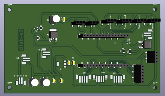
The schematic of the designed PCB is shown below and could be read from left to right. Solar-USB-C1 is the input from battery and the LDO 3.3V is U1 (indicating that the 3.3V rail starts from there).
Week 15
-
Week 16
-
Week 17
-
Week 18
-
Week 19
-
Week 20
-