Week 7 : Computer-Controlled Machining
The advantage of CNC milling over laser cutter (i.e. computer-controlled cutting vs computer-controlled machining) is that thick wood boards could be machined and also more complex three-dimensional shapes could be made. The combination of CAD and Computer-Aided Manufacturing (CAM) - translating design into machine instructions for CNC production - is used to generate toolpaths that substract material to produce the final physical geometry of the part.
Week 7 assignment could be categorized as follows:
-
Group assignment
- Lab safety training
-
Individual assignment
- Design, milling, and assembly (shelve/stackable organizer)
Basics of CNC milling
- Common wood sheet materials
| Material | Description | Pros | Cons | Good CNC Cut Output (chips vs dust) |
|---|---|---|---|---|
| Plywood | Thin sheets of wood stacked with alternating grain (e.g. horizontal vs vertical) and glued together. | Strong, dimensionally stable, good structural strength. | Surface not as smooth as MDF. | Mix of small chips and splinters, slight dust from glue layers. Clean edges if sharp bit is used. |
| MDF (Medium-Density Fiberboard) | Wood fibers and resin pressed into dense sheets with a very smooth surface. | Very smooth finish, great for painting and CNC. | Heavy, produces fine dust when cut. | Mostly fine dust. Very little to no chips (this is normal for MDF). |
| MDO (Medium-Density Overlay) | Plywood with a resin-treated fiber overlay for a smooth, durable face. | Strong like plywood, smoother surface, good for paint. | More expensive than plywood, harder to find. | Chips from plywood core + smoother dust-free top layer cutting. Cleaner face than plywood. |
| OSB (Oriented Strand Board) | Compressed wood strands (a mix of leftover woods) bonded with adhesives. | Very inexpensive, structurally strong. | Rough appearance and not suitable for flexures (not flexible). | Large irregular chips + dust. Very inconsistent chip formation due to strand structure. |
| Lexan (Polycarbonate)/bulletproof glass | Extremely impact-resistant transparent plastic. | Nearly unbreakable, high impact resistance, clear. | Expensive, scratches easier than glass. | Curled plastic shavings or chips. If dust appears, it indicates melting or overheating. |
-
Stock means raw piece of material/workpiece a user starts with before cutting or shaping it.
-
Tooling
Tool Description Pros Cons Typical Uses Drill Bit Cutting tool designed to make round holes by cutting straight down into material. Fast and efficient for holes, simple to use, widely available. Cannot cut sideways well, limited to hole-making. Drilling holes for screws, bolts, dowels. End Mill Milling cutter with cutting edges on the tip and sides that can remove material in multiple directions. Can cut sideways, make slots, pockets, and contours; versatile in CNC and milling machines. More complex to use, slower for simple holes, can break if plunged incorrectly. CNC routing, slot cutting, pocketing, profiling, shaping parts. -
End mills cutting
- The most common end mills have 2 to 4 flutes (cutting edges).
- Fewer flutes are used to remove material quickly. More flutes are used for finishing passes to provide smoother surface.
- Center-cutting vs non-center-cutting
- Center cutting: Cutting edges meet at the middle, allowing the tool to plunge straight down into the material.
- Non-center-cutting: Evacuates chips more efficiently and are commonly used for side cutting.
- Up-cut vs down-cut
- Up-cut: Pull material upward during cut. This produces a clean finish on the bottom of the workpiece but a rough surface on top.
- Down-cut: Push material downward during cut. This produces a clean finish on the top but rough underside. A common strategy is to start with a down-cut pass then follow with an up-cut pass for the bottom finish.
- Chips must be cleared efficiently; otherwise overheating and poor cutting quality may occur.
-
CNC Machining Operations (Types of milling cuts)
Cut Type Description CNC example Laser cutter analogy Slot A long, narrow channel cut into material. Cutting a track for a bolt or sliding part. A through cut Pocket A recessed area that does not go all the way through. Carving a cavity for electronics or magnets. Laser engraving / rastering Contour Cutting along the outline of a shape. Following curved design edges. Vector cutting Profile Cut Cutting the final outer shape of a part. Separating part from stock material. Final laser cut -
Machine Parameters & Cutting Behavior
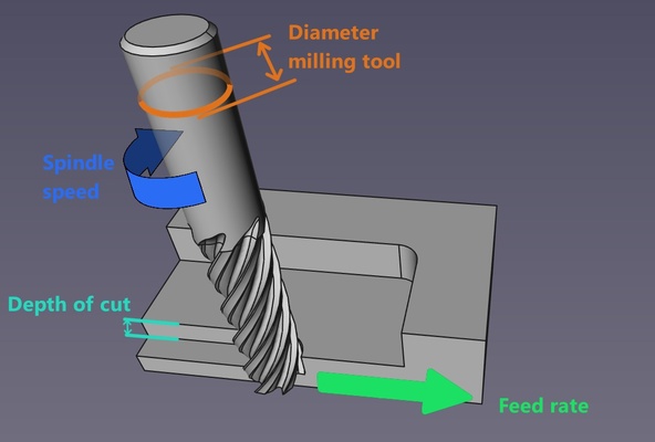
- CNC milling parameters
- Milling diameter (mm): Determines cut width and material removal rate.
- Speed (RPM): Spindle rotation speed.
- Feed rate (mm/min): Tool movement speed across material.
- Depth of cut (mm): Vertical cutting depth per pass.
-
Toolpath behavior
- Kerf
- Runout: Slight deviation in tool rotation due to misalignment or vibration.
- Conventional vs climb milling : Please refer to available online resources
-
Part stability methods
- Tabs vs onion skinning
- Tabs: Small bridges that keep parts attached to stock.
- Onion skinning: Thin remaining layer at bottom to hold parts in place.
- Tabs vs onion skinning
- CNC milling parameters
-
Workholding method
- Vises
- Bar clamps
- Sacrificial nails: Nails used to fix workpiece into sacrificial layer.
- Sacrificial layer: Base layer protecting machine bed during full-depth cuts.
Source: ChatGPT by OpenAI, March 2026, cncyangsen
Lab safety training
Wood dust is highly flammable and the combination of high spindle speeds, friction, and heat could potentially ignite the accummulated dust and chips
CNC wood milling were highlighted during the start of the week as a powerful tool that can easily catch fire if not used safely. A code of practice is in place at the makerspace and its content is summarised below ; similar to Week 3 : Computer-controlled cutting, but with additional information mainly due to difference in scale compared to the laser cutter:
- Training and qualifications : Only authorized users may operate the laser cutter; new users must be supervised
- Personal protective equipment : Wear safe clothing, safety glasses (protect against flying particles and sparks), heat-resistant glove, respirator P2/P3, ear protection in environments with high noise levels.
- Preparations and operating rules : Never leave the machine unattended while running and ensure everything is working properly before starting the work at the laser cutter. This includes simulating the toolpath prior the actual job, rigid clamping of the workpiece on the machine bed, proper toolbit installation, etc.
- Emergencies : Familiarise with the emergency stop button. Use fire extinguisher if condition is deemed safe, else evacuate
- Cleaning up after operation : Everything should be switched off and cleaned for the next work
- Reporting and maintenance : Report any unsual behaviours to the makerspace's administrator
- Do not leave the cut unattended : Always remain present while a cut is in progress to ensure safe operation and to respond immediately if any issues arise.
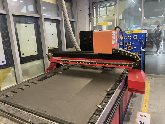
In relation to the above, the technical specification of the machine used are as follows :
Further details on the CNC machine including original manual (as perhaps there are more references in mandarin), please refer to Chaihuo's 2025 and Chaihuo's 2026 Week 7 group assignment.
| Specification | Details |
|---|---|
| Manufacturer | Tiancheng Xinli CNC |
| Model | 3STC-1325A |
| Workbench Size | 1450mm × 2900mm |
| Processing Range | 1300mm × 2500mm |
| Z-axis Travel (i.e. spindle vertical distance range ) | 180mm |
| Feed Height (i.e. clearance between gantry vs. all below it) | 200mm |
| Positioning Accuracy | ±0.15/300 mm |
| Spindle Speed | 0 – 24000 rpm |
| Tool Diameter | 3.175mm, 4mm, 6mm, 8mm, 10mm, 12.7mm |
| Spindle Power | 3 kW water-cooled |
| Cooling System | Water pump |
This machine uses a pressure plate system (i.e. uses mechanical force like clamps, screws, bolts) to fix the workpiece using physical force rather than suction (i.e. not vacuum-based) to prevent the material from shifting. In this case bolts and fastener
Design, milling, and assembly
The material available at the makerspace is grey High-Density Fiberboard (HDF) with dimensions of 1220 mm × 2440 mm × 18 mm. HDF is a denser, harder, and smoother variant of MDF. The design is therefore adjusted based on the material's properties and the operational parameter of the previously mentioned CNC. An image of the material could be seen further below.
Design
The design is inspired by users that live in short-term accommodation with the need of shelve/stackable organizer that can be easily assembled and disassembled - so joints are interlocked with each other without permanent fasteners or glue. This modular concept then also means users can add or remove layers depending on their storage needs.
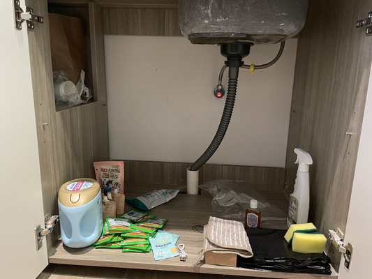
Look at that messy and free space!
Onshape is used as the design software and so this section focuses on its features that were used to develop the final parameteric design.
Dogbones were incorporated to allow square internal corners to be accurately machined using rounded cutting bits. The use of standard fillets (without dogbones) should be perhapsexplored in future iterations that perhaps would increase the aesthetic of the final product.
Based on previous machining tests in 2024 and 2025, the kerf for this material was determined to be approximately 0.2mm. This means that for a target dimension of 18 mm, an offset must be applied by adding 0.2 mm on each side, resulting in a total compensation of +0.4 mm to achieve a proper fit. This value is added to the base dimension of all the slots. See the assembly section to see the results.
Several techniques using Onshape were already documented in previous weeks. Additional methods that were not yet explored before that was used to complete the final design are outlined below.
Linear pattern
Using the linear pattern tool in Onshape, multiple slots can be created efficiently in a single operation by duplicating a base slot feature along a defined direction and spacing. This allows for consistent geometry, improved modelling speed, and greater accuracy compared to manually sketching each slot individually. Useful for multiple creation of slots and joints.
Dogbones add-on
Rather than manually making/sketching the dogbones, the CNC Overcuts add-on that is compatible with Onshape was explored.
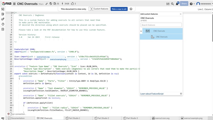
To add this add-on (or in Onshape it's called Custom Feature), user can locate the "+" button at the top of the interface and add the the desired feature. This feature should then appear in the user's project interface and then could be applied directly by selecting the relevant edges or faces where dogbones are needed.

3D to 2D sketch for DXF export
The CNC milling machine requires DXF file and so the 3D model that already incorporates the features from above must be first converted into a clean 2D. This is done using the Use feature that projects edges of the 3D geometries in Onshape. The steps are as follows :
- Use the “Use” tool to project edges from the respective parts into the sketch
- Create a single master sketch on one consistent plane for export. It is recommended to sketch the border of the actual material dimensions that allows user to better visualize and position the parts within the available area.
- Right click the part sketches and select "copy sketch", select the (blank) master sketch and then paste
- Repeat for the other part sketches. Then export the final master sketch as DXF file.
Milling
The milling process is further divided into three steps :
- G-code creation with Mastercam Mill X6 software
- G-code conversion for HCarve 3A software compatibility
- CNC execution via HCarve 3A software based on generated G-code.
USB Compatibility for CNC Milling Software
The CNC milling setup may require a USB drive formatted as FAT32, as some systems do not recognize NTFS-formatted drives.
-
Steps to check USB format :
- Insert your USB drive.
- Open File Explorer.
- Right-click the USB drive → select Properties.
- Look for the File system field (e.g., FAT32 or NTFS).
-
Steps to format a USB drive to FAT32 :
- Insert the USB drive.
- Open File Explorer.
- Right-click the USB → select Format.
- Choose FAT32 under File system.
- Click Start.
G-code creation
Please refer to resources online for instruction details on the Mastercam Mill X6 software.
The G-code creation is also divided into several steps :
-
Toolpath selection + depth of cut e.g. whether the tool cut inside or outside of a geometry
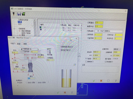
The direction of cut and the depth of cut can be configured directly in the software settings after selecting the contour milling option, as shown in the window below.
Remember to cut inside (or within) the feature first, and only then proceed to outside/profile cuts. This helps maintain material stability during machining - just like laser cutting
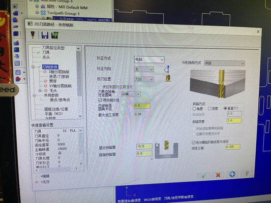
The setting is configured to Left (左) with a 3 mm depth of cut per pass, as indicated in the figure. In this context, “Left (左)” refers to the toolpath being offset to the left side of the reference line. For comparison, the figures are added below for context.
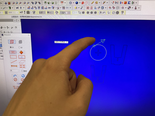
Left from reference line 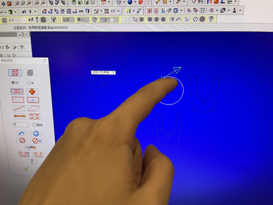
Right from reference line The result of selecting left and right from the reference line will affect the path of the cut.
It can be seen from the video above that the bottom slot and the bottom-right slot are cut on the outside, resulting in unintended or “weird” geometries.
The depth of cut determines the number of passes required based on the total cutting depth (e.g. 18.3 mm would require approximately 6–7 passes).
Depth of cut/pass depth should not exceed the milling bit's diameter. Cutting deeper than the tool diameter increases the material removed per pass (one complete movement of the tool along the material for a cut) which puts excessive stress on the tool and spindle**
-
Cutting parameter setup
The milling operation is governed by the following formula :
\[ \text{Feed Rate} = \text{Spindle speed} \times \text{Number of Flutes} \times \text{Chip Load} \]Where :
- Spindle speed (RPM) : Adjust in combination with feed rate to achieve the desired chip load
-
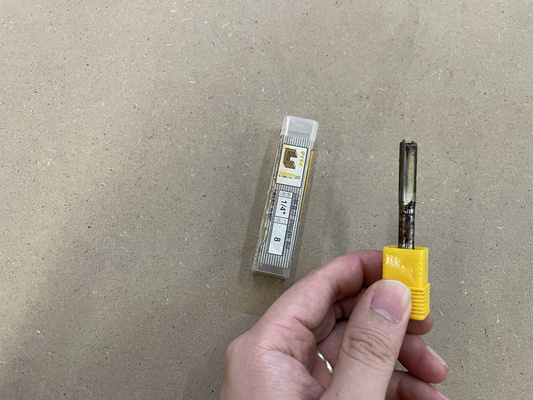
Number of flutes : The end milling tool available in the makerspace is an 8 mm diameter, 2-flute, center-cutting end mill. Therefore, the number of flutes used for calculations is 2.
-
Chip load/Feed per tooth (FPM) : Although the material used is HDF, the reference chip load value is taken from MDF guidelines as a baseline. A typical value of 0.1 mm/tooth is used, based on the recommendations from the Mekanika CNC feeds and speeds guide
Chip load and cutting behavior
Chip load is not directly defined in most CNC software. Instead, the user sets the feed rate and spindle speed (RPM), and the resulting chip load is derived from these values and the tool geometry.
-
Chip load too low:
- The tool rubs against the material instead of cutting efficiently
- Generates excess heat and may cause burning
- Physical indicators: very fine dust (instead of chips), burn marks, darkened edges
-
Chip load too high:
- Cutting forces become excessive
- Can lead to tool overload, chatter, and unstable cutting
- Physical indicators: chipped or broken end mill, visible tool deflection, rough or torn surface finish
Previous experience used the following machining parameter and is used as a baseline standard for the test:
- Feed rate : 5000 mm/min
- Spindle speed : 15000 RPM
These settings could be adjusted at another tab of the same window as the depth of cut section.
It is important to note though that the software assumes a 4-flute tool, resulting in a calculated chip load of 0.0833 mm/tooth. However, the actual cutting tool is a 2-flute tool, which means the real chip load is 0.1667 mm/tooth. This is significantly higher than the software assumption and exceeds the reference value for HDF (i.e. 0.1 mm/tooth).
Result and observation : the machining process produced fine dust as expected for HDF material. No burn marks or darkened edges could be seen on the workpiece surface. This indicates that the current cutting parameters remain acceptable despite the higher chip load. Future tests though may benefit from a lower FPT/Chip load in order to potentially minimize tool wear.
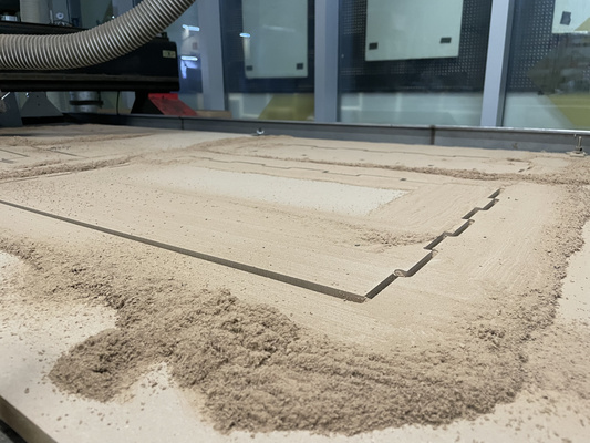
The design was originally intended to include pocket features (partial-depth cuts) rather than fully cutting through the material. However, after several attempts, it appears that the software does not correctly recognize or apply these pocketing operations - this should be explored in the future. As a result, all toolpaths are currently executed as through-cuts, removing material completely instead of maintaining specified depths
G-code conversion
The old CNC machine does not support an automatic return-to-origin function; therefore, any return-to-origin commands must be removed from the G-code before execution. This process can be supported by AI by comparing previously edited and successfully executed files from past years with the original user-generated G-code.
CNC execution
The zero point needs to be set correctly before starting the machining operation and this could be done manually at HCarve 3A software. The user then could double check the toolpath if it behaves as expected by clicking F8 to generate the CAM path.
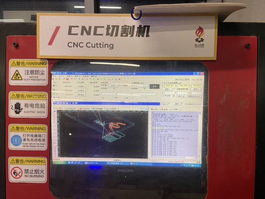
In this example, there are 5 rectangular-like items that are outside of the boundaries.
Other hotkeys to be aware of that could be useful during the execution :
- F9 : Start cutting (execute G-code program)
- F10 : Pause operation
- F11 : Stop operation completely
During machining, the operator should remain attentive at all times. If any abnormal behavior is observed, press F10 immediately to pause the machine and prevent potential damage or safety hazards.
Assembly
Overall, the components are able to hold themselves in place without additional force, as demonstrated in the videos above. The designed joint gap could potentially be reduced to around 0.3 mm to achieve a tighter fit compared to the current 0.4 mm design. However, this may increase the difficulty of assembly by requiring more force to fit the parts together.

Given that the difference between the two tolerances is relatively small and could potentially also be due to the runout of the tool, the current fit is considered satisfactory. The assembly process is straightforward and can be completed in under 10 minutes without the need for specialized tools or excessive effort.