Week 3: Computer-controlled cutting
Computer-controlled cutting week. For my individual assignment I built a parametric hex snowflake construction kit in Onshape, exported DXF, laser-cut the pieces on plywood, and assembled them into a 3D snowflake. On the lab’s Cricut Explore vinyl cutter I cut one hex puzzle piece from the same DXF in blue heat-transfer vinyl — steps, machine specs, and materials are under vinyl cutter. The group section covers Chaihuo laser characterization (kerf, clearance, safety). My earlier violin bracket laser work stays on Week 2.
Individual assignment: parametric hex snowflake kit
Task and why a snowflake kit
The individual brief asks for a parametric construction kit that accounts for laser kerf and can be assembled in more than one way without glue. I wanted something small enough to iterate on one sheet of plywood but still teach me the same lesson as a big press-fit project: if board thickness or kerf changes, I should change one variable, not redraw every slot by hand.
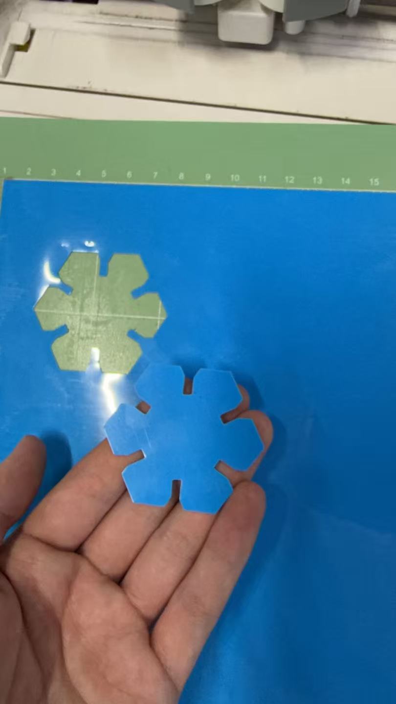
I chose a six-fold snowflake: an inscribed hexagon hub with six rectangular spokes that slot into matching partners. Chamfers on the tabs make the first push-fit less brutal. After the cut I could stack the pieces flat, fan them into a star, or build the full 3D snowflake shown in the hero photo—it is the same kit, different assemblies.
How this page meets the assignment
Mapped to the Fab Academy computer-controlled cutting checklist:
| Requirement | Evidence on this page |
|---|---|
| Linked group assignment / kerf learning | Group section; kerf variable in Onshape |
| Parametric 2D design documented | Onshape workflow (variables and constraints) |
| Laser-cut construction kit | Laser cut video; assembly |
| Original design files + hero shots | DXF download; finished snowflake |
| Vinyl cutter | Cricut Explore workflow (Design Space, heat-transfer vinyl, cut video, puzzle piece) |
Parametric design in Onshape
I modeled entirely in Onshape as a single sketch driven by variables. The
screenshots follow the order I actually built it: hex hub first, then spokes sized with kerf,
then chamfers, then export. The feature tree names I kept are diameter (inscribed
hex hub, I started at 40 mm), kerf (spoke tab width tied to group comb
results), length (overall spoke arm), and chamfer_distance1 /
chamfer_distance2 (joint edge chamfers so press-fit assembly is less brutal than
square corners).
Step 1 — inscribed hexagon hub
I sketched a regular hexagon from an inscribed circle and bound its size to
diameter so the whole hub scales together.
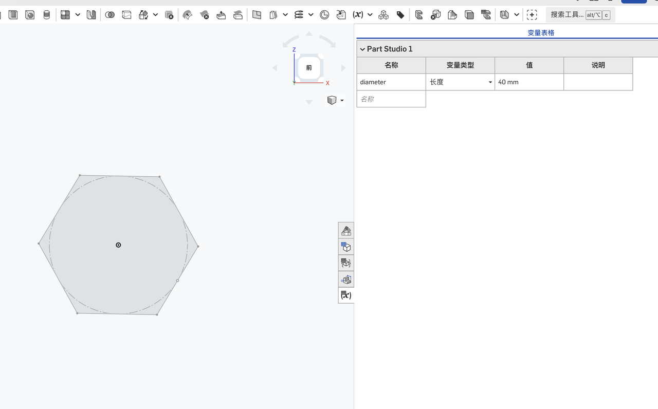
diameter drives the hub (40 mm in this capture).
Step 2 — six spokes with kerf and length
I added six rectangles for the snowflake arms, set width = kerf and
length = length, then constrained each rectangle to the hex hub with
coincident and center constraints so the pattern stays symmetric when
I nudge parameters.
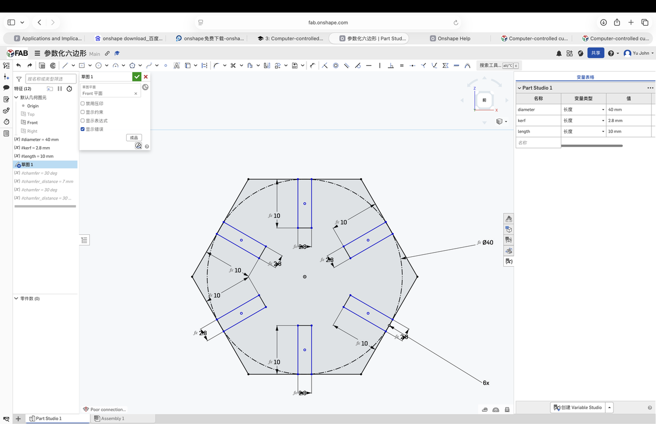
kerf and length, constrained to the hub.
Step 3 — chamfer variables and geometry
Square slot corners fought me on the first dry fit, so I introduced
chamfer_distance1 and chamfer_distance2 and applied chamfers to the joint
edges instead of redrawing the slots.
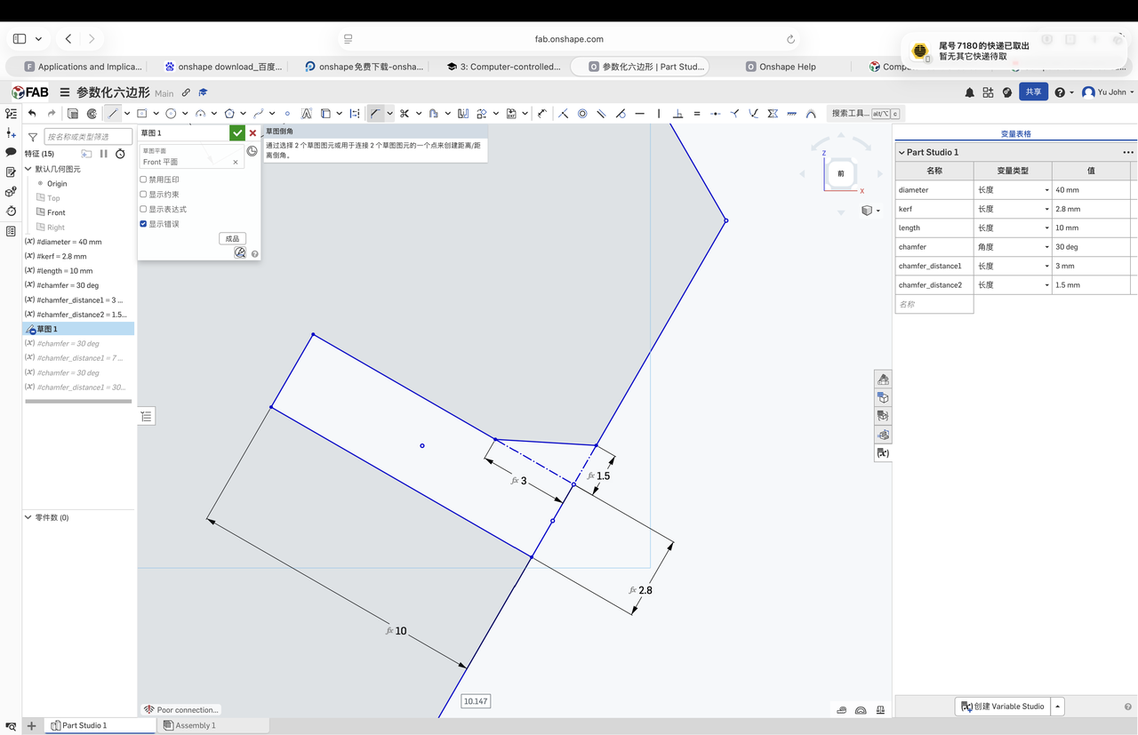
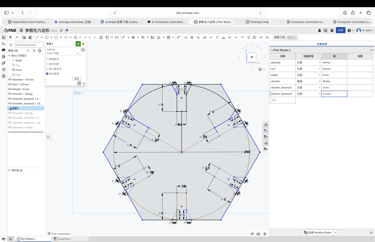
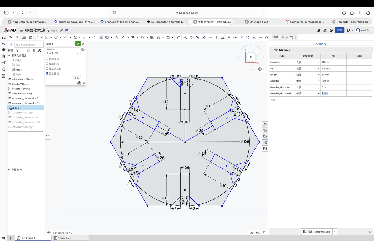
chamfer_distance2 to balance fit vs. ease of assembly.
Step 4 — DXF export for the laser
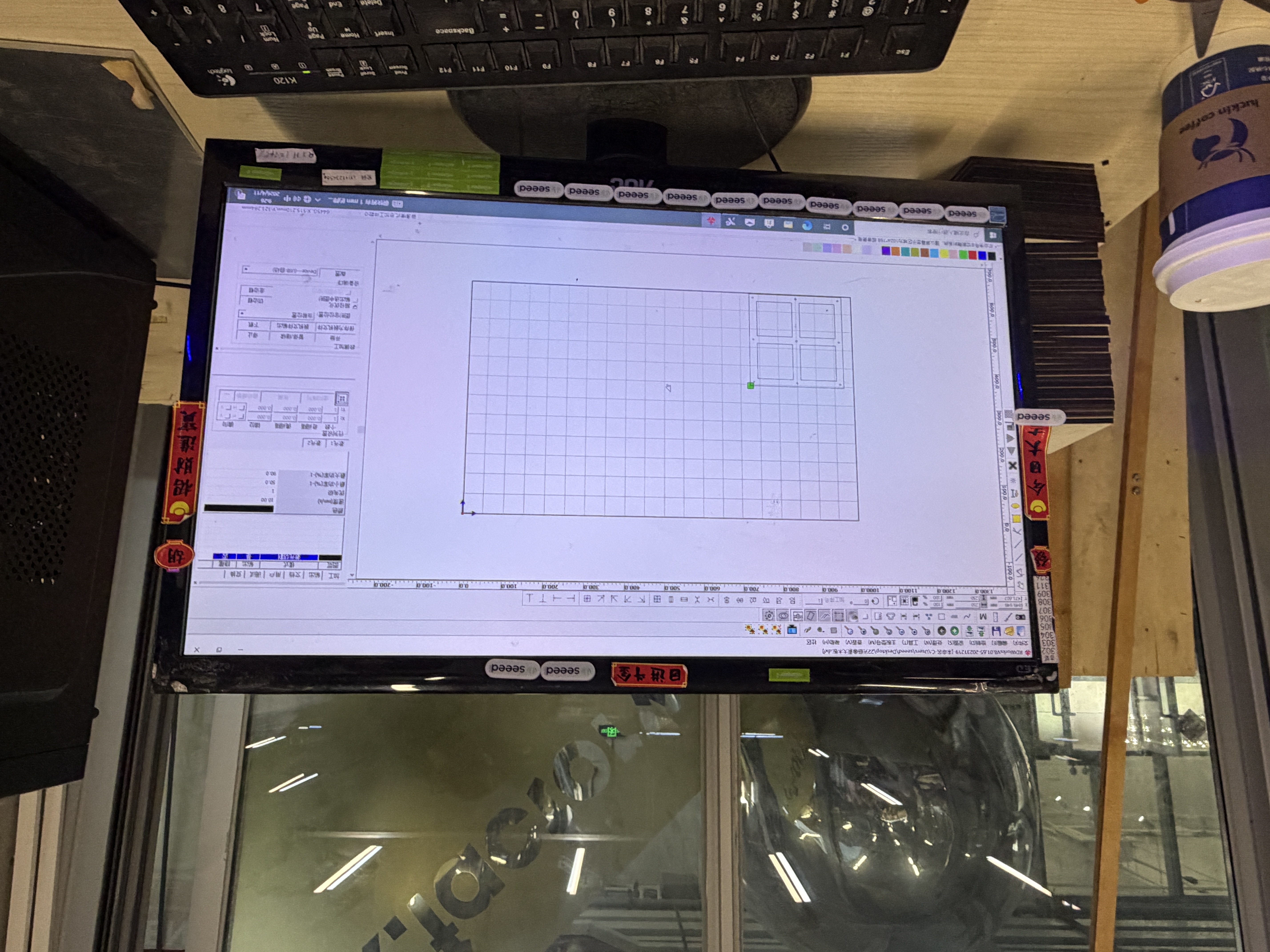
From the finished sketch I exported a flat DXF for the lab laser workflow (same file linked under Design files). I checked scale and units in the export dialog before walking the file to the cutter PC.
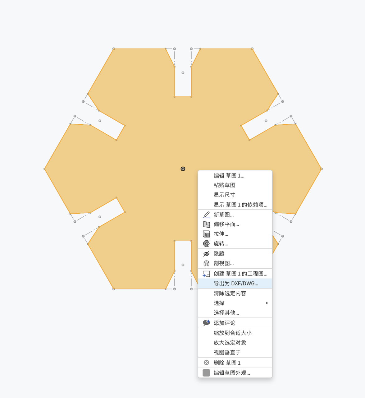
hex-snowflake-kit.dxf on disk.
Laser cutting
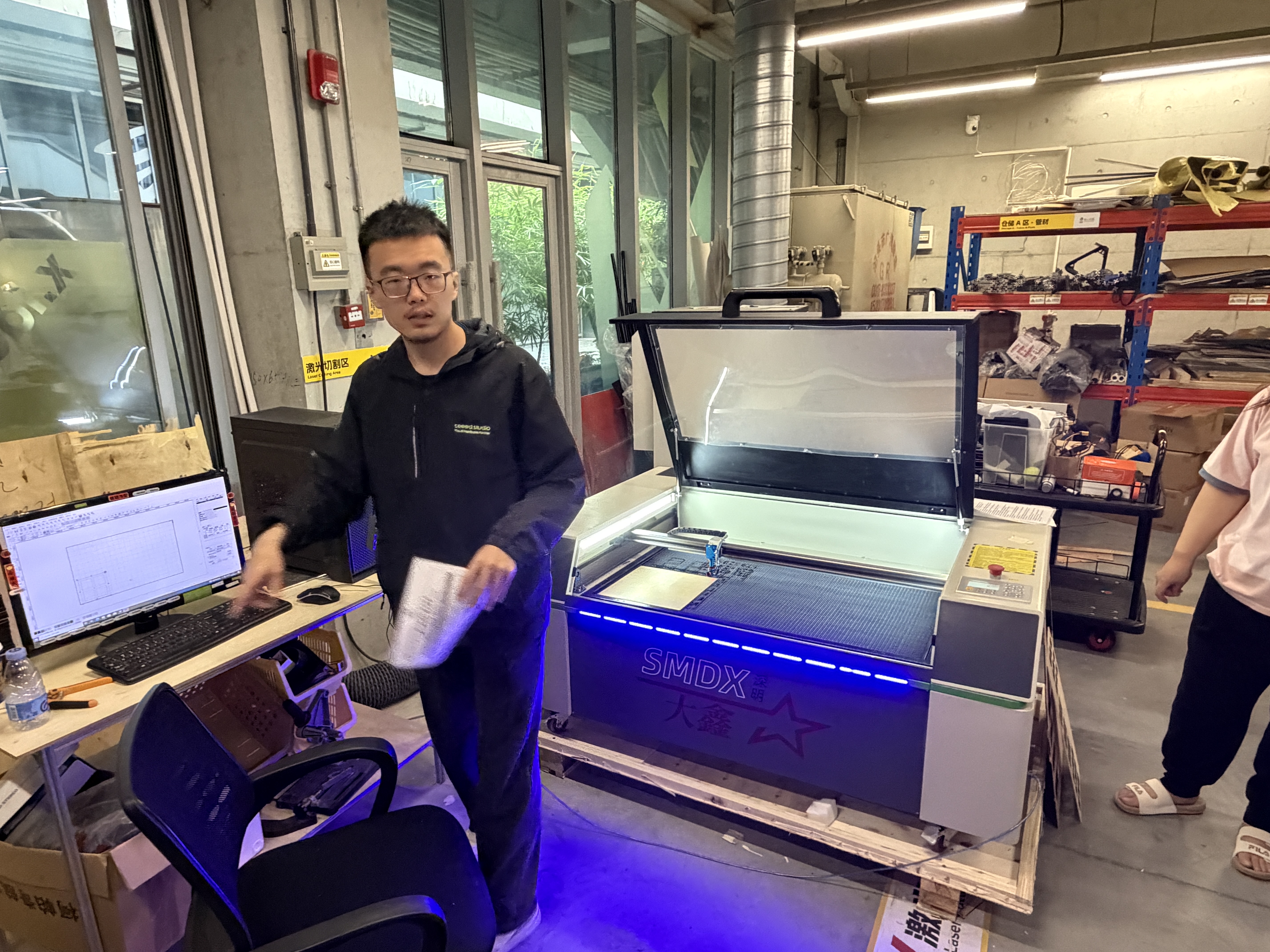
I transferred the DXF to the laser workstation, picked cut settings for our approved plywood (power/speed from lab notes and the group characterization table), and ran the job. The clip below is the cut on the machine. Useful when I need to remember engrave-vs-cut order and how long six duplicate spokes take on one sheet.
week03-laser-cutting.mp4: transferring the file and cutting the snowflake kit.
Assembly and finished snowflake
Off the bed I deburred tabs with a knife, then pressed pairs together starting from the hub. Chamfers helped more than I expected. The square-edged trial in CAD felt fine until real kerf tightened the slots. The assembled star and the final 3D snowflake are different views of the same kit.
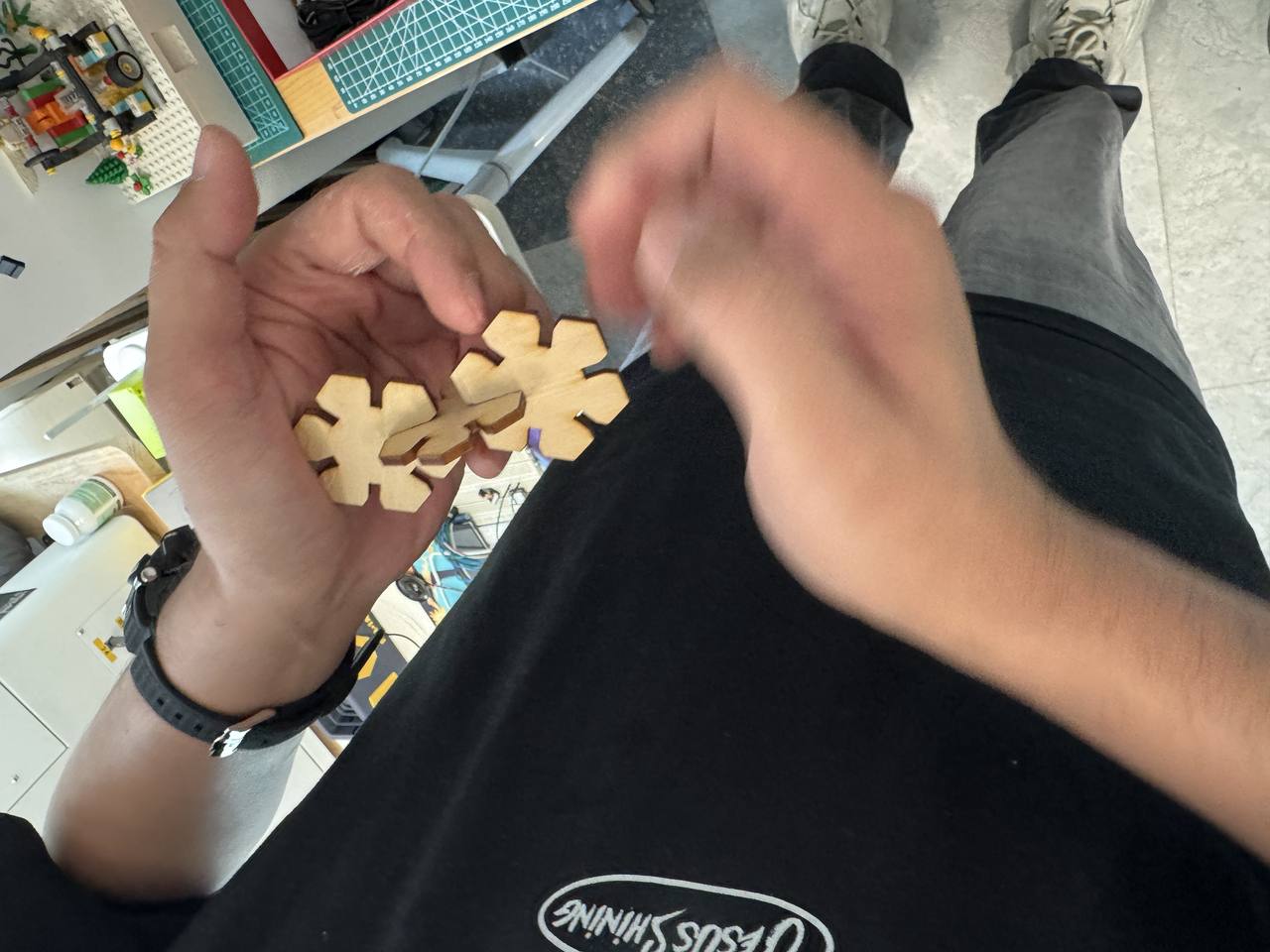
Finished 3D snowflake

Vinyl cutter: one hex puzzle piece on Cricut Explore
The individual brief also asks me to cut something on the vinyl cutter. I reused
the same parametric hex kit rather than downloading a sticker file. From the flat
hex-snowflake-kit.dxf I isolated one hex interlocking puzzle piece,
a single hub-and-tab unit from the snowflake layout — and cut only that piece on
blue heat-transfer vinyl (iron-on stock). I did not run a separate paper or cardstock
cut; this job is my vinyl-cutter deliverable for the week.
Machine and software
The bench unit is a Cricut Explore with a physical Smart Set material dial and front-panel Load/Unload and Go buttons. I drive it from Cricut Design Space. I downloaded and install from that page, sign in, pair the Explore over USB or Bluetooth, then send jobs from the Make It screen. Design Space is the CAM layer: it turns my uploaded vector into mat layout, blade passes, and the on-machine prompts.
| Item | What I used / observed |
|---|---|
| Machine | Cricut Explore at Chaihuo — Smart Set dial, Load/Unload and Go on the front panel |
| Software | Cricut Design Space (desktop); project synced to the paired Explore |
| Cutting mat | StandardGrip, 30.5 cm × 61 cm (12 in × 24 in) |
| Blade / clamp | Fine-Point Blade in clamp B; clamp A empty for this job |
| Operation type | Basic cut (through-cut), single mat, mirror off, one puzzle piece per job |
| Design size on mat | About 9.87 cm × 8.55 cm after scaling in Design Space |
| Stock material | Blue heat-transfer vinyl (iron-on / 热转印乙烯基) on the carrier sheet |
Materials
I cut blue heat-transfer vinyl (iron-on sheet on its carrier) face-up on a StandardGrip green mat, using the Explore’s Fine-Point Blade for the through-cut. The vector came from the same Onshape export as the laser kit: hex-snowflake-kit.dxf; I isolated one puzzle piece from the full snowflake layout.
Operation steps (Design Space → machine)
Screenshots follow the order I actually walked through: import the DXF, scale on the canvas, pick mat loading, lay out on the virtual mat, confirm material and blade, then run the physical cut.
Step 1 — Upload the DXF
In Design Space I used Upload → Upload image/file and selected
hex-snowflake-kit.dxf. The importer brought in the full snowflake layout; I kept only
the geometry I needed for one puzzle piece in the next step.
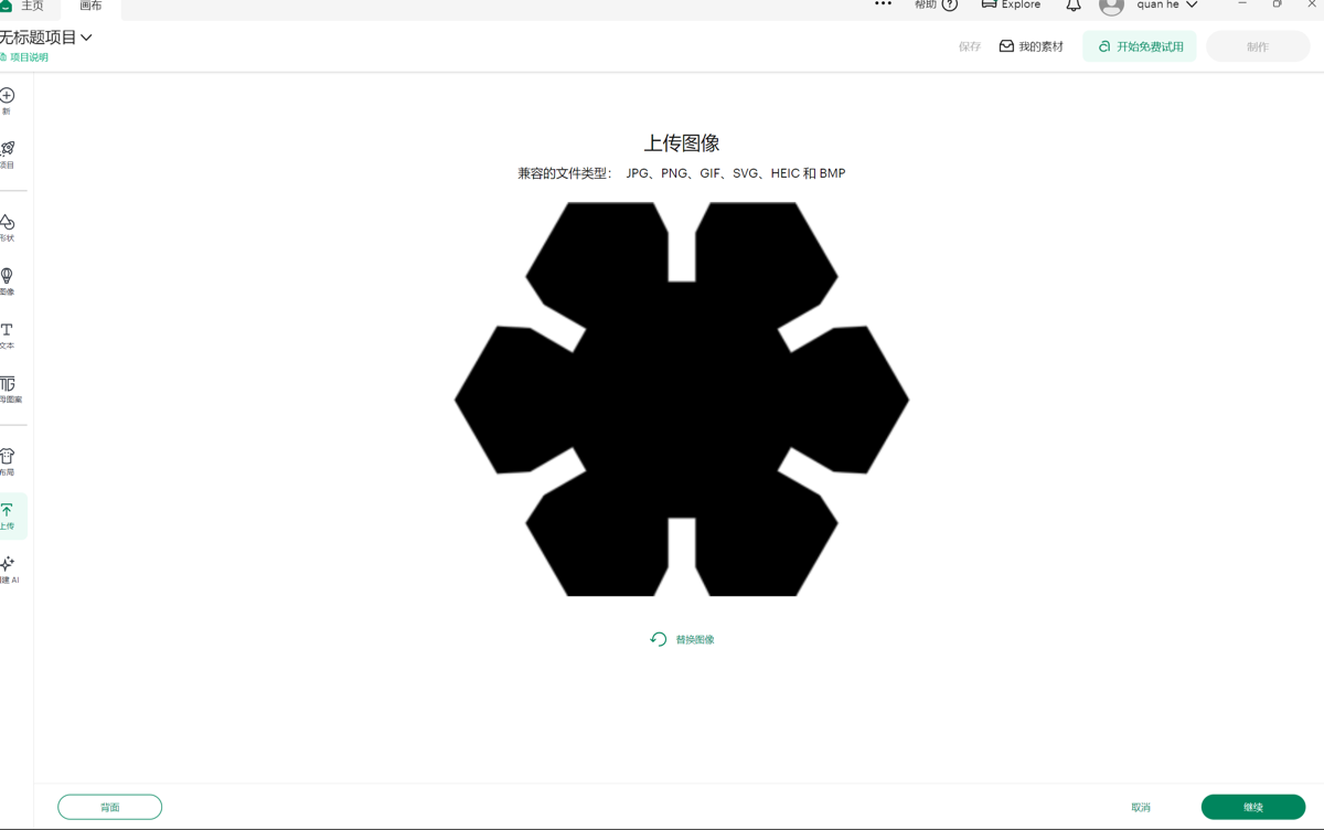
hex-snowflake-kit.dxf in Design Space before sizing.
Step 2 — Isolate one puzzle piece and scale
I deleted the extra snowflake arms and kept a single hex puzzle piece in the top-left of the grid, then set dimensions to about 9.87 cm × 8.55 cm so it fit inside the 12 in mat width with room for the rollers to grip the edges. Layer operation stayed Basic cut.
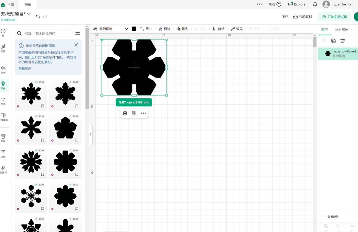
hex-snowflake-ki… layer set to basic cut.
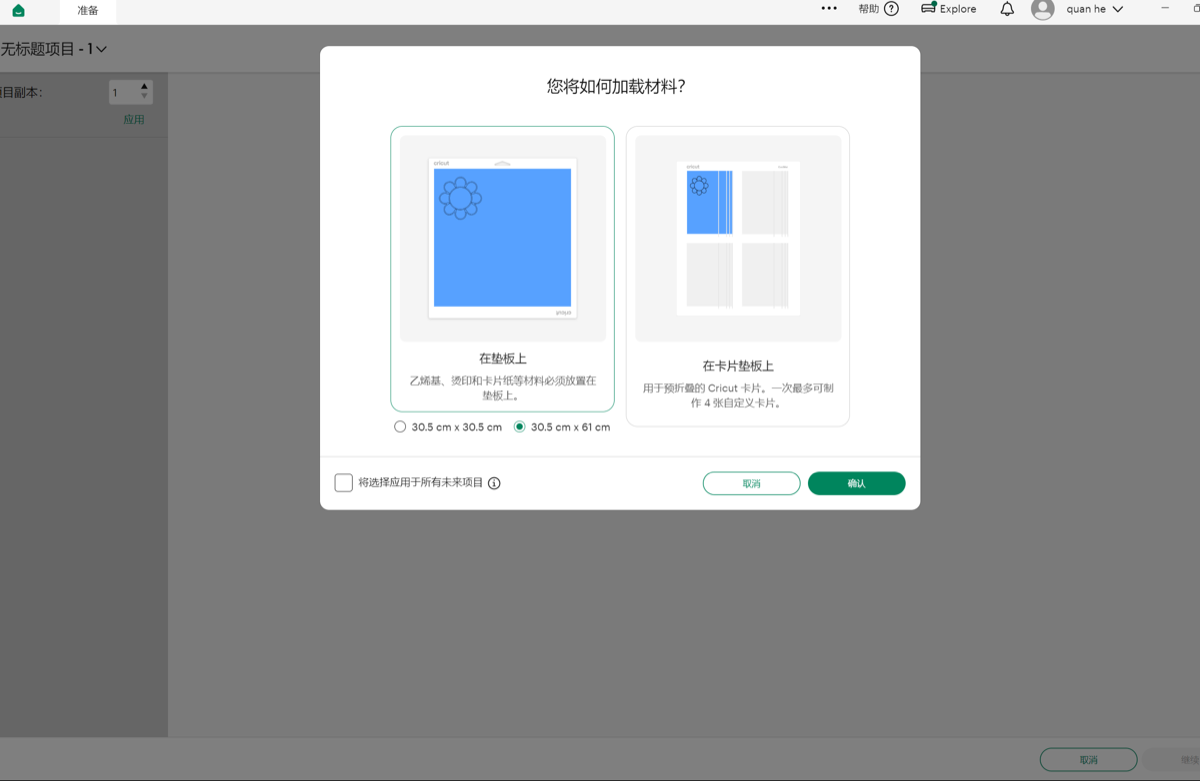
Step 3 — Choose “on mat” loading
On Make It I chose On mat (vinyl / iron-on workflow), not the card mat, and confirmed the 30.5 cm × 61 cm mat size.
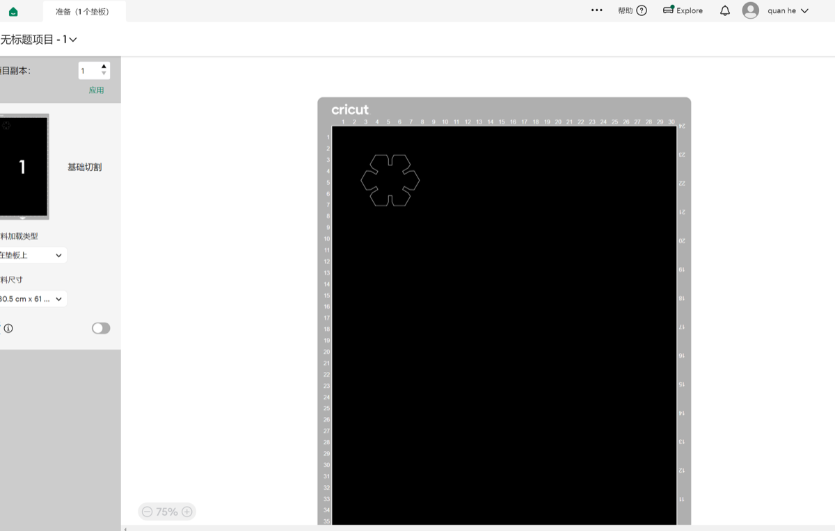
Step 4 — Prepare mat layout
The prepare screen shows the single puzzle piece nested in the top-left of the virtual mat (black cut area on the mat preview). One copy, mirror off.
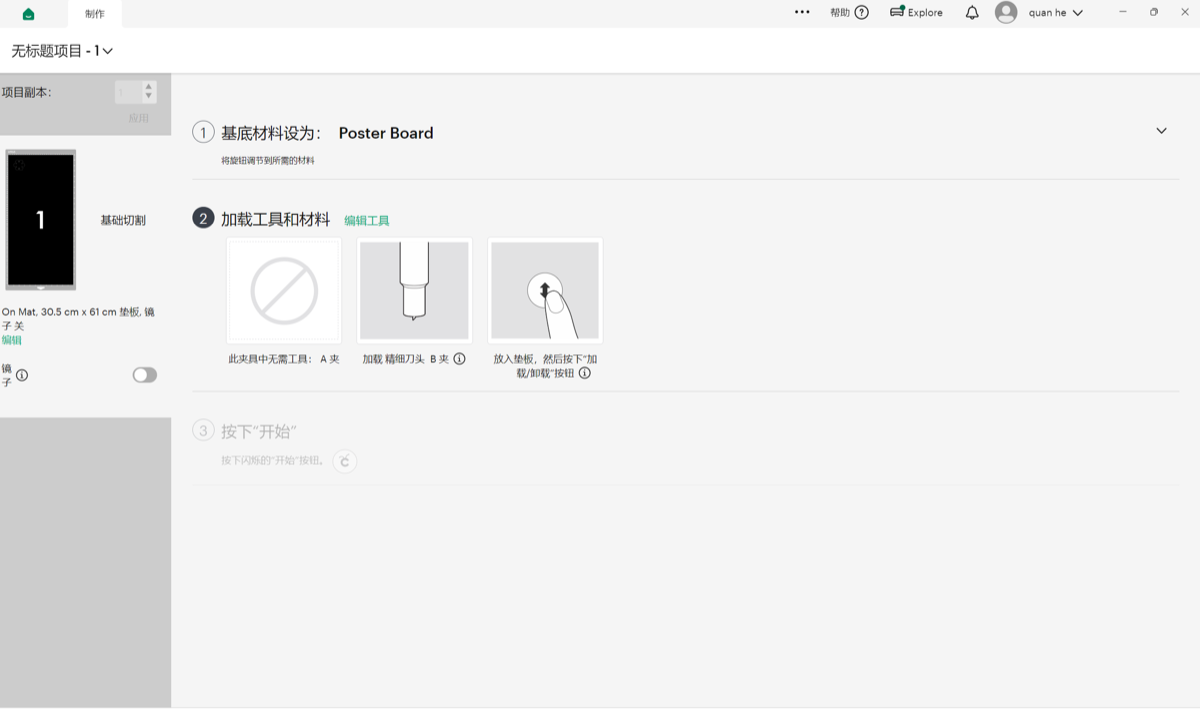
Step 5 — Material preset and blade prompts
With blue heat-transfer vinyl on the StandardGrip mat, Design Space walked me through the Explore checklist: set the Smart Set dial to the iron-on / vinyl preset, load the Fine-Point Blade in clamp B, insert the mat until the rollers catch, press Load/Unload, then the flashing Go button when the prompt unlocked.
Step 6 — Cut on the machine
The clip is the Explore during the through-cut: rollers advance the mat, the blade traces the hex tab outline and slot notches in the heat-transfer vinyl. I watched the first corner before walking away. Thin iron-on can lift if the mat is dusty or grip is weak.
week03-cricut-cutting.mp4, Cricut Explore cutting the hex puzzle piece in heat-transfer vinyl.
Step 7 — Final output
After the cut I lifted the blue hex interlocking puzzle piece off the mat on its carrier sheet. The rectangular slots match the kerf-aware tabs from the same parametric sketch — a quick check that my DXF export survived a second cutter even when I only cut one piece from the layout.
Design files (download)
Flat layout exported from Onshape: hex-snowflake-kit.dxf. If the browser opens the DXF instead of downloading, use Save As.
Reflection
Building the kit in Onshape forced me to treat kerf as a real dimension, not a
note on the group page. Linking slot width to kerf meant when the group comb test
nudged my value, I could regenerate the DXF instead of hand-editing six slots. Chamfers were
the other lesson: parametric sketches only stay pleasant to assemble if you plan for
entry angles, not just nominal width.
Running one puzzle piece on the Cricut Explore taught me that “vinyl cutter” in the syllabus really means knife plotter + CAM software, not a different geometry language. Design Space handled the import, but I still had to isolate a single piece from the full snowflake DXF and watch mat margins before sending the job. Tighter numeric rows in the group laser table (power/speed/kerf for this plywood lot) are still on my list. For the final project I may reuse the hub-and-spoke pattern for decorative iron-on panels once both cutters’ kerfs are logged side by side.
Group assignment
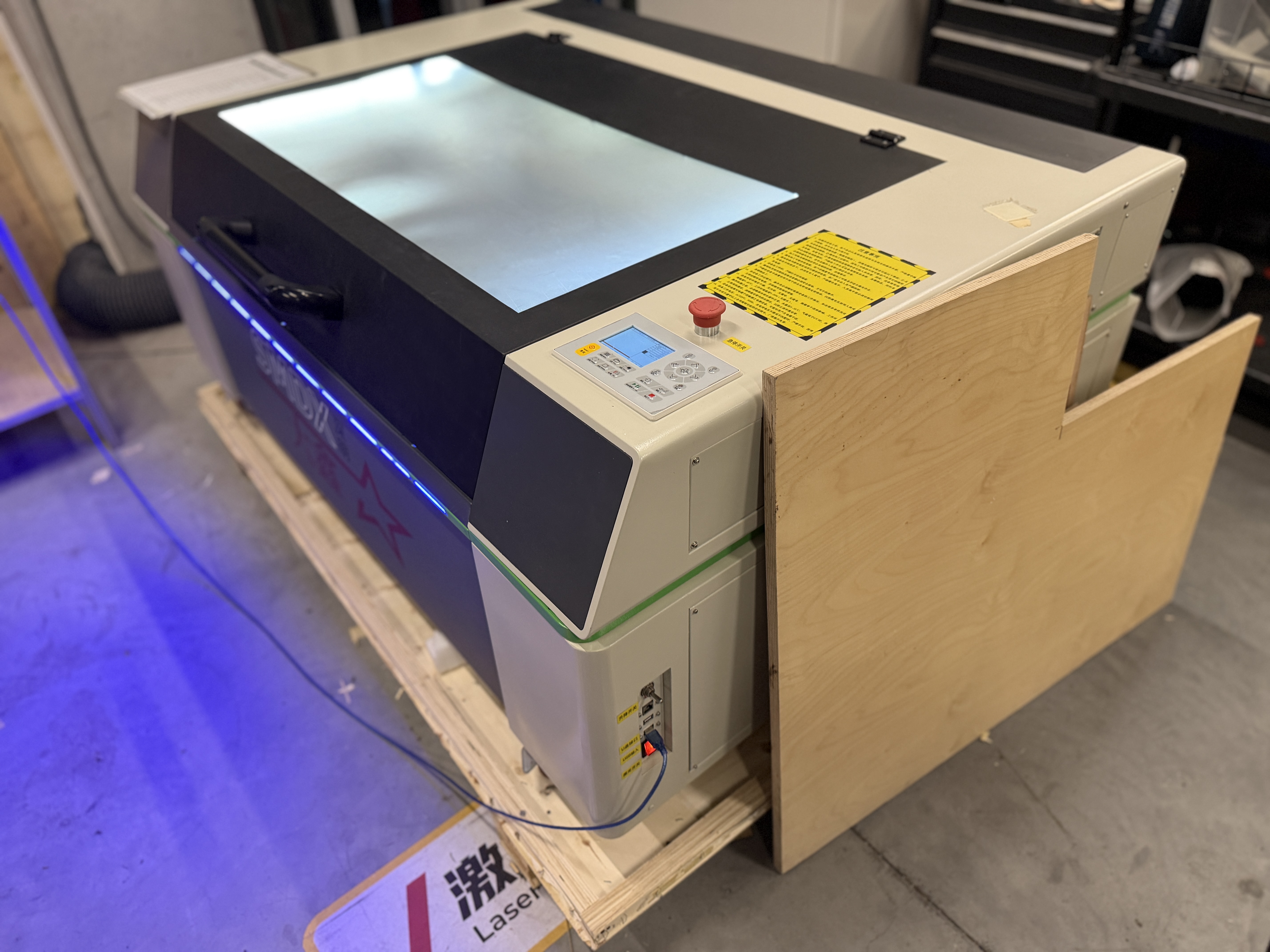
Guangzhou (Chaihuo) — group documentation: laser-cutter characterization, joint tolerance tests, and GitLab-based collaboration.
Abstract
At Chaihuo we documented how our local laser cutter behaves in practice: focus versus cut quality, usable power levels, speed for cut versus mark, pulse frequency or effective scan rate (as the machine exposes it), measured kerf, joint clearance for press-fit or slot joints, and material types the site approves. We also ran a laser tolerance study (comb test and spacing sweep) to find reliable gaps for finger joints and inlays. Photos and short clips from the runs are in the repo via our usual GitLab workflow (fork → branch → merge request).
1. Safety training and approved use
We completed the lab’s laser safety training before cutting. In my notes I kept the Chaihuo-specific rules that affected the job directly: ventilation on, no banned plastics, fire watch during the run, and supervision while the lid was closed.
2. Machine characterization
We recorded focus, power, speed, frequency/rate, kerf, joint clearance, and materials in a table. Calipers, comb coupons, and close-up photos were enough to connect the settings to real fit.
| Parameter | Notes / method |
|---|---|
| Focus | Relate focus setting to edge quality; record nominal vs. best visual cut. |
| Power / speed / rate | Ranges used for cut vs. mark; align with control UI labels for your machine. |
| Kerf | Measured from test cuts or comb coupons (calipers / photo overlay). |
| Joint clearance | Press-fit or slot joints: gap that fits reliably on this cutter. |
| Approved materials | List materials allowed at Chaihuo for laser processing. |
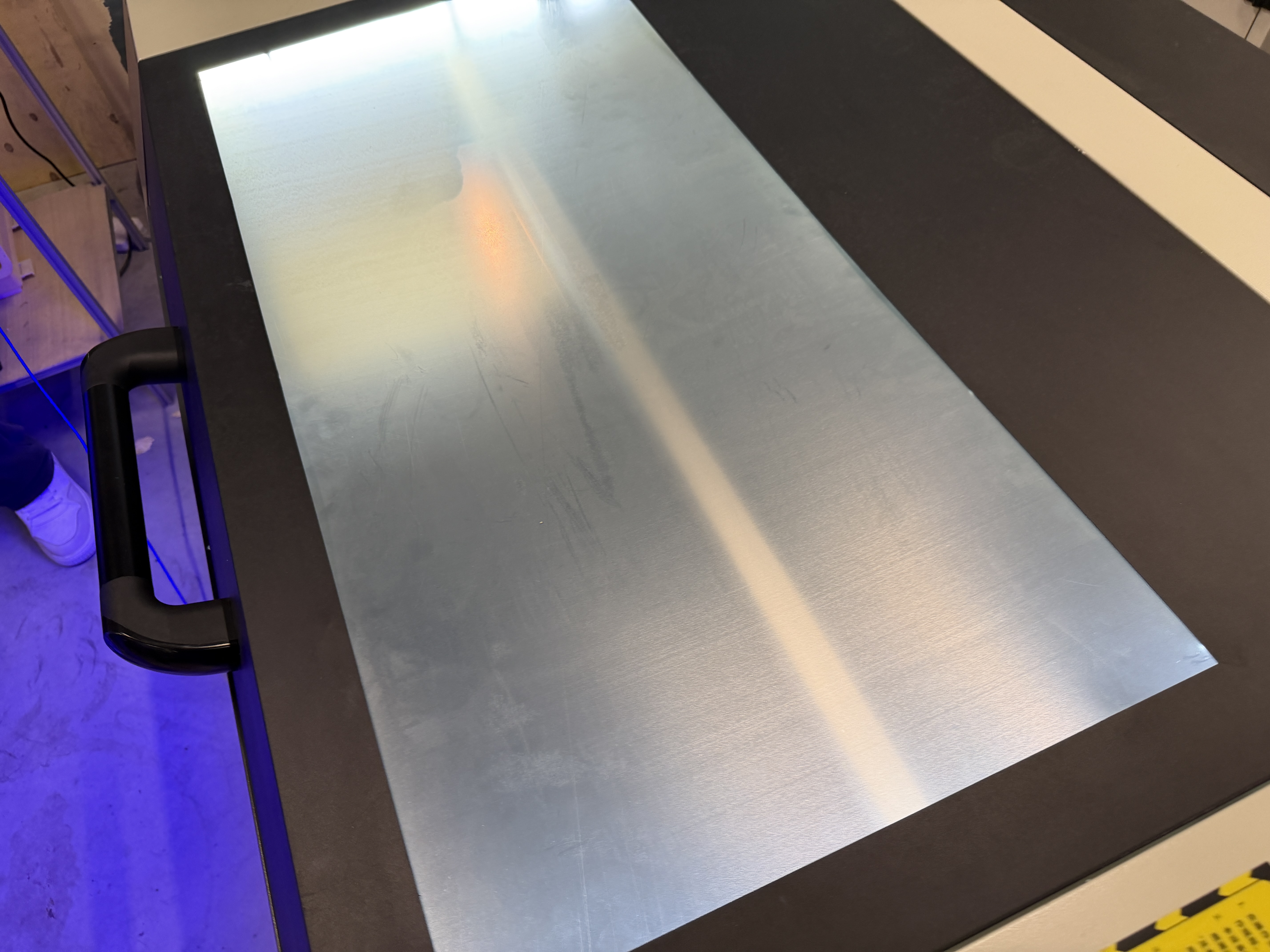
Lab photos (cutting workflow)
3. Tolerance testing (e.g. comb test)
We cut comb coupons and swept slot spacing to see which gaps press-fit cleanly on this machine. The photos below show kerf, joint clearance, and the coupons we kept for the group table.
4. Collaboration: GitLab and the Chaihuo site
We used the usual fork and merge request flow so photos and tables could be reviewed before they landed on the Chaihuo group site.