Week 4: Embedded programming
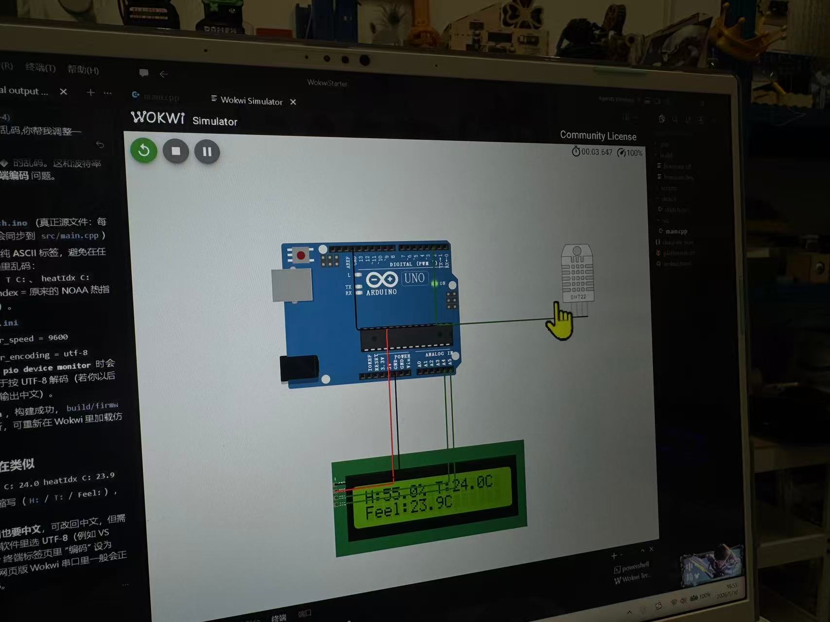
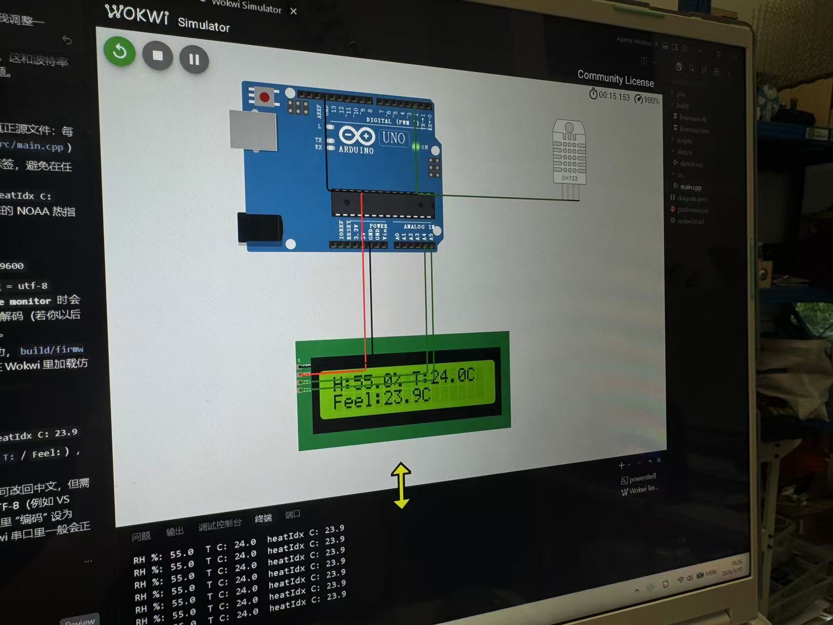
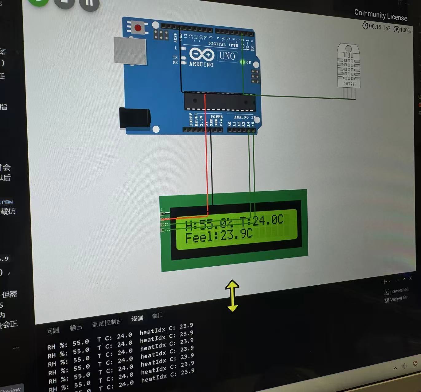
This week was embedded programming. For my individual assignment I first built a Wokwi simulation in Cursor Desktop:
an Arduino Uno reads a DHT22 temperature and humidity sensor, shows the values on a
1602 LCD with an I2C backpack at address 0x27, and prints the same
readings to the serial monitor. After the simulation worked, I built the same type of
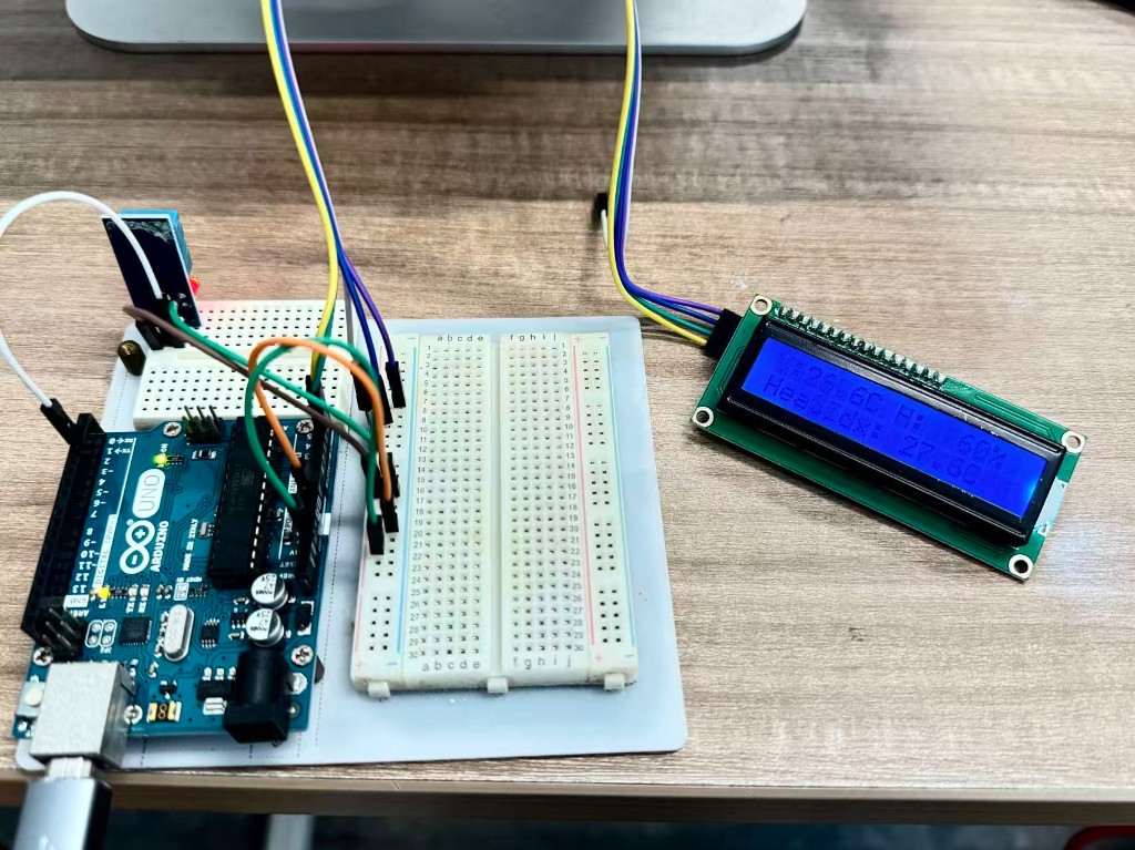
circuit on the bench with a real Arduino Uno, DHT11, and LCD1602 I2C module to verify
that the program also worked on physical hardware.
Individual assignment: Wokwi simulation and physical verification
Assignment checklist
The Fab Academy individual assignment asks us to browse a microcontroller datasheet, write and
test a program for an embedded system, interact with local I/O devices, communicate over a
wired or wireless connection, include source code, and document the programming process. I used
an Arduino Uno R3 (ATmega328P) and checked the pinout before
wiring: D2 for DHT data, hardware I2C on SDA=A4 and
SCL=A5. The DHT22 in Wokwi and the DHT11 on the bench are the inputs; the
LCD1602 and serial monitor are the outputs. The LCD talks over I2C; the Uno
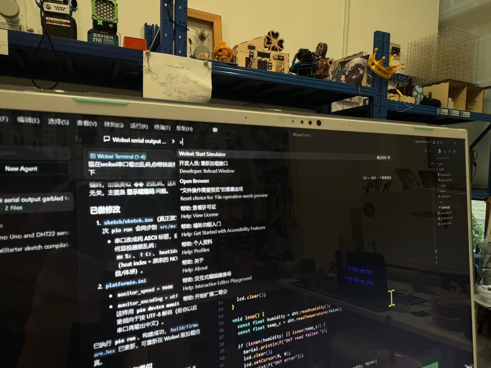
reports readings over Serial. I edited the sketch in Cursor Desktop, ran the
Wokwi extension, and checked both LCD and serial while debugging. Source lives at
code/week04/wokwi/sketch.ino (simulation)
and
code/week04/platformio-uno-dht11-lcd/src/main.cpp
(physical test); screenshots on this page cover both paths. Group work is in the
group section below.
1. Task and motivation
My final project will rely on temperature and humidity sensors to watch the plant’s growing environment, so I wanted to prove the circuit and code before I solder anything. I used Wokwi simulation so I could iterate on wiring and software without blocking on lab bench time.
Within that goal, I wanted to test the basic sensing path before working with physical wiring: environment → sensor → microcontroller → readable output. The DHT22 gives temperature and humidity readings, and the LCD makes the result visible without depending only on the serial monitor.
I chose a DHT22 in Wokwi because it is a common classroom sensor, has better resolution than a DHT11, and works fine for indoor temperature and humidity readings. On the bench I used a DHT11 because that was the real module I had available, and it uses the same DHT library pattern. I used a 1602 LCD with an I2C backpack because it needs only two signal wires instead of many parallel LCD pins.
My workflow was: install the Wokwi extension in Cursor Desktop, create the
circuit in diagram.json, write the Arduino sketch, start the
simulator, check the LCD and serial monitor, then rebuild the circuit with real
parts and document both results with photos and source code.
2. Learning
I pushed myself to learn beyond the simulator: I wanted to see what a real
character LCD actually looks like on the bench, so I hunted around the lab and
found an LCD2004 with an I2C backpack (my Wokwi build still
uses a 1602 because that part is easy to fit in the diagram, but
the hardware idea is the same). On the back I noticed
three small address pads and no obvious label telling me the I2C
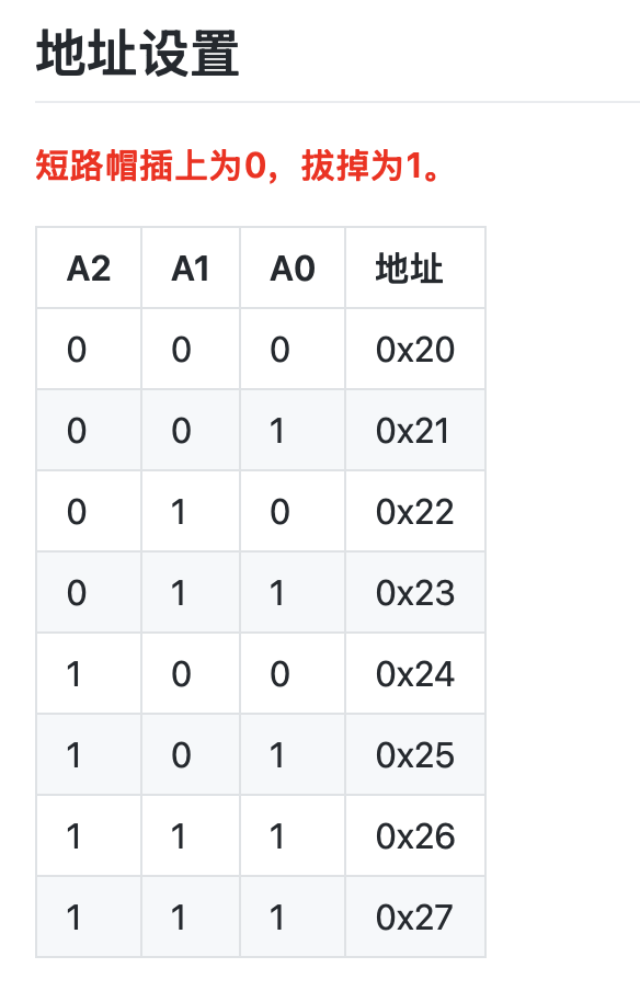
address out of the box. I looked up
DFRobot’s Chinese wiki for the classic backpack style (
A0/A1/A2 as the low address
bits). There I learned how jumper soldering maps to the
0x20–0x27 range, and how to match a real module to the right
LiquidCrystal_I2C address, then I confirmed that against the pads on
the board I had in hand.
The DHT22 uses a single-wire digital protocol. In the Arduino environment I used the DHT library, which also recommends waiting about 2 s between readings. The LCD backpack uses I2C. Many boards in the lab use a backpack based on an I/O expander such as the PCF8574, where those three address lines pick one of eight addresses in the 0x20–0x27 range (other chip families sometimes default to 0x3F instead). In my Wokwi project and in code I used address 0x27, consistent with what I inferred from the wiki and from inspecting the solder bridges on the backpack.
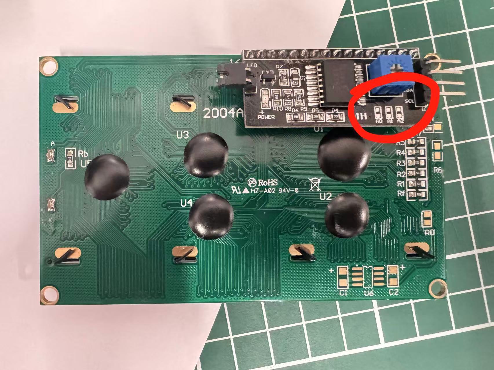
How the I2C address is set on the backpack
On the DFRobot DFR0063-style I2C LCD module, the wiki documents that the last
three address bits are controlled by small solder jumpers (or bridges) on the
back of the backpack: each of A0, A1, and
A2 can be read as 0 or 1
depending on how that pad is connected, and the combination picks the
7‑bit I2C address. Below is the lab module (LCD2004) from the back. The three pads
that set the address are circled; then the manufacturer table I pulled from the
wiki to interpret them and lock in 0x27 for
LiquidCrystal_I2C.
0x27 versus another
value in code. (Simulation still uses a 1602 for convenience.)
Reference: DFRobot — I2C LCD1602 module DFR0063 (documentation and address setup).
The Wokwi DHT22 data pin is labelled SDA, but it is not the same SDA line as I2C. In this circuit, the DHT22 data pin goes to D2. The LCD is the part that uses real I2C, with SDA → A4 and SCL → A5 on the Arduino Uno.
For the microcontroller reference, I checked the ATmega328P documentation and the Arduino Uno pinout. This confirmed the digital pin and I2C pin choices before I finished the Wokwi wiring.
I also kept one earlier ESP32-S3 draft in the repository as a reference for a
possible future board change:
code/week04/esp32-s3-dht-lcd-main.cpp.txt. This week’s documented circuit and screenshots use the Arduino Uno project
in diagram.json.
3. Plan
I planned the week as a straight line: install Wokwi in Cursor, build an Uno + DHT22 + LCD1602 diagram, wire power/ground/DHT data/I2C, add the DHT and LCD libraries, write a sketch that reads every 2 s and updates LCD plus Serial, capture screenshots and commit source, then rebuild on the bench with a real Uno, DHT11, and LCD1602 I2C module to confirm the same logic on hardware.
4. Process
Step A: Installing Wokwi in Cursor Desktop
I opened Cursor Desktop, hit ⌘+Shift+X for Extensions, searched
for Wokwi Simulator, and installed it. The
Wokwi extension setup guide
covers activation. I opened code/week04/wokwi/ because that folder already holds
diagram.json, sketch.ino, and project settings. From the Command Palette
I ran Wokwi: Start Simulator and watched the serial monitor while values updated.
If the simulator does not start, I first check whether the opened folder contains
diagram.json, whether sketch.ino sits beside it, and whether the
libraries listed in
libraries.txt are available.
Step B: Building the simulation circuit
The wiring in my diagram.json is:
| Signal | Component pin | Arduino Uno pin |
|---|---|---|
| 5 V | DHT22 VCC, LCD VCC |
5V |
| GND | DHT22 GND, LCD GND |
GND |
| DHT22 data | DHT22 pin labelled SDA |
D2 |
| I2C | LCD SDA / SCL |
A4 / A5 |
I set the LCD to I2C mode and used address 0x27. On real hardware, if the LCD stays blank, I would first check the I2C address and the contrast setting on the backpack.
Step C: Code and libraries
The project uses the Arduino framework. The dependency list is saved as
libraries.txt.
The sketch initializes the LCD, reads the DHT22 every two seconds, calculates
heat index in Celsius, updates both LCD rows, and prints the same values to the
serial monitor. If the DHT read fails, the LCD shows a short error message.
Downloadable source: code/week04/wokwi/sketch.ino.
/**
 * Fab Week 4 — Wokwi: Arduino Uno + DHT22 + LCD1602 (I2C)
 * See diagram.json in this folder for wiring.
 */

#include <Arduino.h>
#include <Wire.h>
#include <LiquidCrystal_I2C.h>
#include <DHT.h>

#define DHT_PIN 2
#define DHTTYPE DHT22

#define LCD_I2C_ADDR 0x27
#define LCD_COLS 16
#define LCD_ROWS 2

DHT dht(DHT_PIN, DHTTYPE);
LiquidCrystal_I2C lcd(LCD_I2C_ADDR, LCD_COLS, LCD_ROWS);

static void showSensorError(void) {
  lcd.clear();
  lcd.setCursor(0, 0);
  lcd.print("DHT read error");
  lcd.setCursor(0, 1);
  lcd.print("chk D2 / DHT22");
}

void setup() {
  Serial.begin(9600);
  lcd.init();
  lcd.backlight();
  lcd.clear();
  lcd.setCursor(0, 0);
  lcd.print("Uno + DHT22");
  lcd.setCursor(0, 1);
  lcd.print("LCD I2C 0x27");
  delay(800);
  dht.begin();
  Serial.println(F("Arduino Uno — DHT22 @ D2, LCD1602 I2C SDA=A4 SCL=A5 addr=0x27"));
}

void loop() {
  delay(2000);

  float rh = dht.readHumidity();
  float tC = dht.readTemperature();

  if (isnan(rh) || isnan(tC)) {
    Serial.println(F("[err] DHT read failed — wiring / type / 2s sample"));
    showSensorError();
    return;
  }

  float hiC = dht.computeHeatIndex(tC, rh, false);

  char line0[17];
  char line1[17];
  (void)snprintf(line0, sizeof(line0), "T:%4.1fC H:%4.0f%%", tC, rh);
  (void)snprintf(line1, sizeof(line1), "HeatIdx:%5.1fC", hiC);

  lcd.clear();
  lcd.setCursor(0, 0);
  lcd.print(line0);
  lcd.setCursor(0, 1);
  lcd.print(line1);

  Serial.print(F("RH: "));
  Serial.print(rh, 1);
  Serial.print(F("%  T: "));
  Serial.print(tC, 1);
  Serial.print(F(" C  HI: "));
  Serial.print(hiC, 1);
  Serial.println(F(" C"));
}
Step D: Running the simulator and serial monitor
Step E: Building the physical circuit after simulation
After the Wokwi result was stable, I still needed to prove the idea with real
parts. I used the lab Arduino Uno, a DHT11 module, a breadboard, jumper wires, and
an LCD1602 with an I2C backpack. The physical sensor was a DHT11 rather than the
DHT22 from the simulation, so I changed DHTTYPE to
DHT11 in the practical PlatformIO sketch. The wiring stayed the same
in principle: DHT data to D2, LCD SDA to
A4, and LCD SCL to A5.
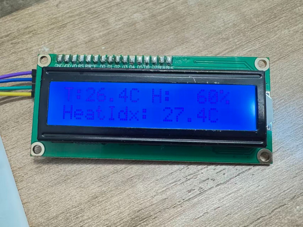
One detail I changed for the real Uno code was the LCD text formatting. On AVR
boards, normal snprintf() float formatting is not always enabled, so
I converted the float readings with dtostrf() first and then placed
those short strings into the two 16-character LCD lines. This made the display
stable and kept each line within the LCD1602 width.
Downloadable physical test source: code/week04/platformio-uno-dht11-lcd/src/main.cpp.
/**
 * Fab Week 4 - PlatformIO: Arduino Uno + DHT11 + LCD1602 (I2C)
 * Wiring: DHT11 data -> D2, LCD SDA -> A4, LCD SCL -> A5.
 */

#include <Arduino.h>
#include <Wire.h>
#include <LiquidCrystal_I2C.h>
#include <DHT.h>

#define DHT_PIN 2
#define DHTTYPE DHT11

#define LCD_I2C_ADDR 0x27
#define LCD_COLS 16
#define LCD_ROWS 2

DHT dht(DHT_PIN, DHTTYPE);
LiquidCrystal_I2C lcd(LCD_I2C_ADDR, LCD_COLS, LCD_ROWS);

static void showSensorError(void) {
  lcd.clear();
  lcd.setCursor(0, 0);
  lcd.print("DHT read error");
  lcd.setCursor(0, 1);
  lcd.print("chk D2 / DHT11");
}

void setup() {
  Serial.begin(9600);
  lcd.init();
  lcd.backlight();
  lcd.clear();
  lcd.setCursor(0, 0);
  lcd.print("Uno + DHT11");
  lcd.setCursor(0, 1);
  lcd.print("LCD I2C 0x27");
  delay(800);
  dht.begin();
  Serial.println(F("Arduino Uno - DHT11 @ D2, LCD1602 I2C SDA=A4 SCL=A5 addr=0x27"));
}

void loop() {
  delay(2000);

  float rh = dht.readHumidity();
  float tC = dht.readTemperature();

  if (isnan(rh) || isnan(tC)) {
    Serial.println(F("[err] DHT read failed - wiring / type / 2s sample"));
    showSensorError();
    return;
  }

  float hiC = dht.computeHeatIndex(tC, rh, false);

  char tempText[6];
  char humText[5];
  char hiText[7];
  char line0[17];
  char line1[17];
  dtostrf(tC, 4, 1, tempText);
  dtostrf(rh, 4, 0, humText);
  dtostrf(hiC, 5, 1, hiText);
  (void)snprintf(line0, sizeof(line0), "T:%sC H:%s%%", tempText, humText);
  (void)snprintf(line1, sizeof(line1), "HeatIdx:%sC", hiText);

  lcd.clear();
  lcd.setCursor(0, 0);
  lcd.print(line0);
  lcd.setCursor(0, 1);
  lcd.print(line1);

  Serial.print(F("RH: "));
  Serial.print(rh, 1);
  Serial.print(F("%  T: "));
  Serial.print(tC, 1);
  Serial.print(F(" C  HI: "));
  Serial.print(hiC, 1);
  Serial.println(F(" C"));
}
Step F: Reproducing the simulation and hardware test
To rerun the simulation, open code/week04/wokwi/ in Cursor Desktop, install the
Wokwi Simulator extension if needed, and run Wokwi: Start Simulator. Confirm
the libraries in libraries.txt, then watch the LCD and serial monitor while the
simulated DHT22 updates. Click the DHT22 part in Wokwi and change simulated temperature or
humidity to stress-test the sketch. For hardware, open
code/week04/platformio-uno-dht11-lcd/ in PlatformIO, upload to Arduino Uno, and
open the serial monitor at 9600 baud. Before powering the breadboard circuit,
check DHT pull-up, LCD I2C address, contrast trimmer, and 5 V/GND wiring.
5. Conclusion
I now have a working path from sensor to screen in both simulation and hardware. In Wokwi, the DHT22 feeds temperature and humidity into the sketch; on the bench, the DHT11 produced real room readings that appeared on the LCD1602. In both cases the LCD shows the numbers locally, and Serial logs the same readings on the computer. The wiring trap I hit in Wokwi is the DHT22 pin label: it says SDA, but in this circuit that pin goes to D2, not the LCD's I2C bus on A4/A5.
Files: the Wokwi project is stored in
code/week04/wokwi/ (sketch.ino,
diagram.json, and libraries.txt). The physical
PlatformIO test is stored in code/week04/platformio-uno-dht11-lcd/.
Screenshots and photos are in images/week04/, including the Wokwi
captures, the combined
result frame, the LCD
backpack address figures, and the two physical verification photos.
This physical check changed my confidence in the assignment: the simulator helped me design the circuit quickly, but the real LCD and DHT11 forced me to check the address, pin wiring, and AVR text formatting. For the final project, this gives me a reusable small pattern: read an environmental sensor, convert the data into a compact display string, and show it locally before using it for more complex behavior.
Group assignment
Guangzhou (Chaihuo) group documentation: comparing toolchains and development workflows across embedded architectures.
Abstract
Our Guangzhou (Chaihuo) group compared the embedded boards we actually use in the lab. We wrote down the compiler, build system, flashing method, debugger options, and the normal edit → build → flash → serial-monitor loop for each board. The useful part for me was seeing where board choice changes the daily workflow, not just the processor name.
Case study: RP2040 vs ESP32-C3 (Seeed XIAO)
The group uses Raspberry Pi RP2040 and Espressif ESP32-C3 as two common Fab-lab paths: RP2040 highlights PIO, dual-core MCU, USB device capability, and an “MCU + external flash” model without on-chip radio; ESP32-C3 adds 2.4 GHz Wi‑Fi and Bluetooth 5 LE on a single-core RISC-V for connected / low-power IoT. The thumb-sized Seeed XIAO RP2040 and XIAO ESP32C3 share a similar footprint, so they are a fair pair for a toolchain comparison.
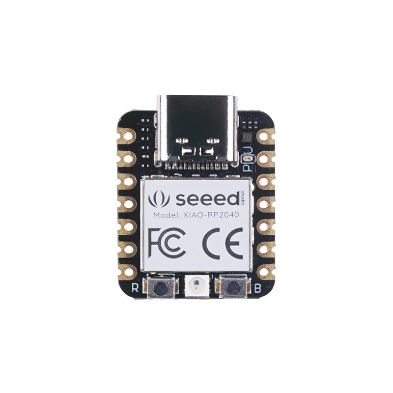
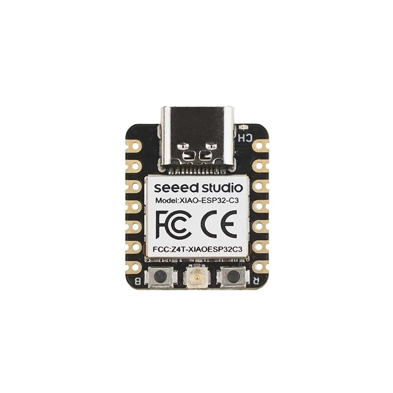
References: Seeed Studio — XIAO series introduction (online) · offline copy in this repo: xiao-series-introduction-seeed-wiki.html.
Chip capabilities (check datasheets for your revision)
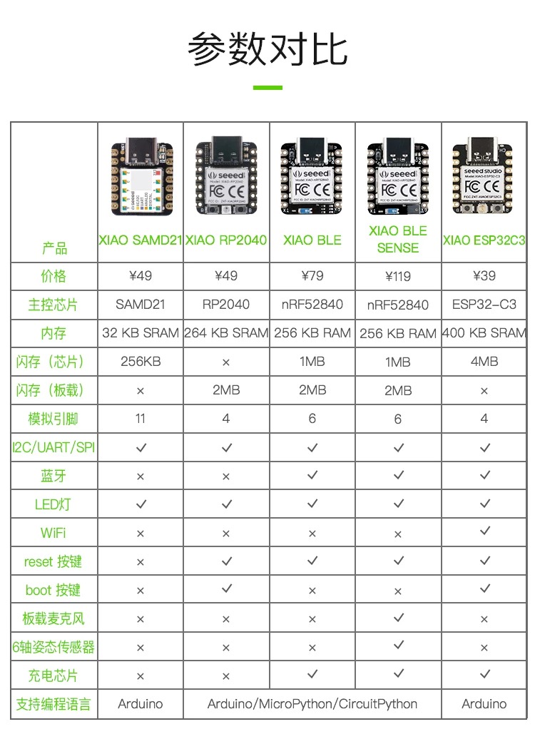
| Topic | RP2040 | ESP32-C3 |
|---|---|---|
| CPU | Dual ARM Cortex-M0+, typically 133 MHz (overclocking depends on board and firmware) | Single-core 32-bit RISC-V, up to about 160 MHz |
| On-chip SRAM | 264 KB (multi-bank) | About 400 KB (partitioning per Espressif datasheet) |
| Program storage | No in-package flash; external QSPI serial flash (often 2–16 MB) | In-package or on-board flash common (~4 MB class for many modules) |
| Wireless | No built-in Wi‑Fi / Bluetooth | 2.4 GHz Wi‑Fi (802.11 b/g/n) + Bluetooth 5 LE |
| USB | USB 1.1 controller + PHY (device or host roles depend on SDK and hardware) | USB serial / JTAG paths for flash and debug (exact options depend on chip revision and board) |
| Notable peripherals | PIO (eight state machines) for custom fast I/O protocols | Rich connectivity: wireless stacks, GDMA, multiple SPI / I2C / UART, PWM, ADC, etc. |
| ADC | On-chip ADC (channels and resolution per RP2040 datasheet) | 12-bit SAR ADC (available GPIO count depends on package / module) |
| GPIO (chip) | Up to about 30 multifunction GPIO | About 22 programmable GPIO (XIAO exposes a subset) |
| Security | Typical MCU features (no integrated wireless security stack) | Optional secure boot, flash encryption, hardware crypto accelerators (series / config dependent) |
| Typical supply | Often about 1.8–5.5 V (confirm on Pico / XIAO schematic) | Often 3.0–3.6 V at the module (USB 5 V via LDO) |
XIAO boards break out far fewer pins than the chip maximum; routing, antenna, and USB front-end affect which GPIO and RF performance you actually get.
Toolchains and workflows (typical class paths)
| Stage | RP2040 (e.g. XIAO RP2040) | ESP32-C3 (e.g. XIAO ESP32C3) |
|---|---|---|
| Official SDK | Pico SDK (CMake + GCC); verify pin map and clocks for XIAO |
ESP-IDF (FreeRTOS components);
idf.py build flash monitor
|
| Arduino | Arduino-Pico core | arduino-esp32 — select ESP32-C3 board target |
| Scripting | MicroPython / CircuitPython (mature on RP2040) | MicroPython and other scripting options; many Wi‑Fi examples |
| Debug | SWD (Pico Probe, DAPLink, etc.); printf-style trace in some setups | OpenOCD + GDB, USB-JTAG paths depending on silicon and board |
| Flash | UF2 drag-and-drop (BOOTSEL) or SWD to external flash | UART download, USB flash; ESP-IDF integration |
| Pre-flash tooling |
clangd, PIO tooling ideas from Raspberry Pi docs, optional static analysis
|
idf.py menuconfig, partition table, Wi‑Fi
provisioning, log levels
|
| Ecosystem strengths | USB gadgets, LED / display drivers, PIO for odd protocols | MQTT / HTTP, BLE, provisioning, OTA (with security care) |
How to choose (for coursework)
For sensor-heavy, real-time GPIO, or custom protocols with no network, RP2040 is often simpler; PIO can implement timing without saturating the CPU. When cloud, phone BLE, or always-on connectivity matters, ESP32-C3 ships wireless stacks and large Arduino / ESP-IDF example sets. For documentation we agreed each board deserves one command sequence from new project through build, flash, serial monitor, and optional step debug, plus one real failure logged (wrong COM port, boot mode, CMake version mismatch, and so on).
1. Architectures and boards
We focused on two boards that show up often in our lab work: RP2040 boards for USB, deterministic GPIO, and PIO experiments, and ESP32-C3 boards when wireless networking or BLE matters more than custom timing.
2. Toolchain inventory per target
For each target we recorded the compiler/toolchain, flash method, debugger path, and default board package or SDK. That gave us a practical checklist for starting a fresh firmware project without guessing which installer or board core was missing.
3. Workflow comparison
We compared project creation, build, flash, serial monitor, and debugging side by side. The failure modes were different enough to matter: RP2040 often turns into BOOTSEL/UF2 confusion, while ESP32-C3 failures more often start with port selection, boot mode, or USB-JTAG support.
4. Languages and pre-deployment tools
We also noted which languages are realistic for class work on each board. C/C++ remains the default for Arduino, Pico SDK, and ESP-IDF examples; MicroPython is useful for quick checks; formatting, static checks, and simulation help most before the first flash.