3d-printed-fu
Download OLED Holder STL (final version)
Week 5: 3D Printing and Scanning
This week felt like a small journey. I wanted to turn a traditional "Fu" (福) pattern into a real 3D object, and at the same time test scanning tools with real objects in daily lab conditions.
My long-term goal is still my final-project idea, a "smart Fu", so every test this week became useful practice. I was not only trying to "get a print," but also trying to understand where and why each step succeeds or fails.
Tools and materials
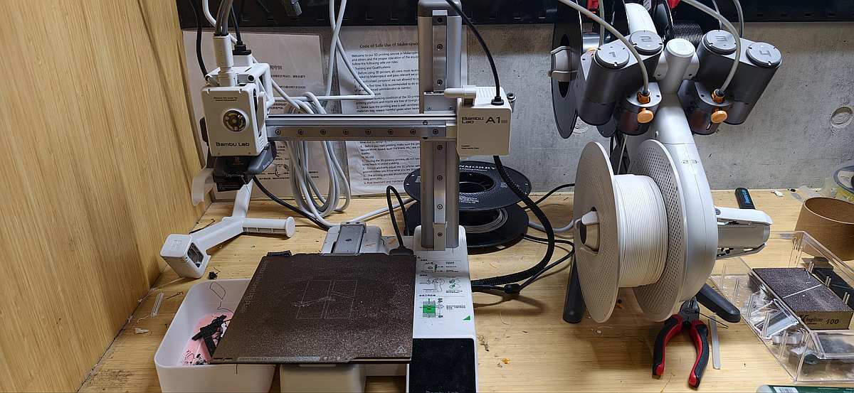
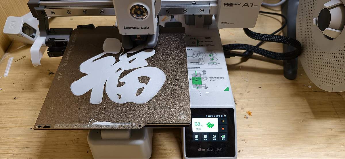
- Printer: Bambu Lab A1 mini
- Material: PLA filament
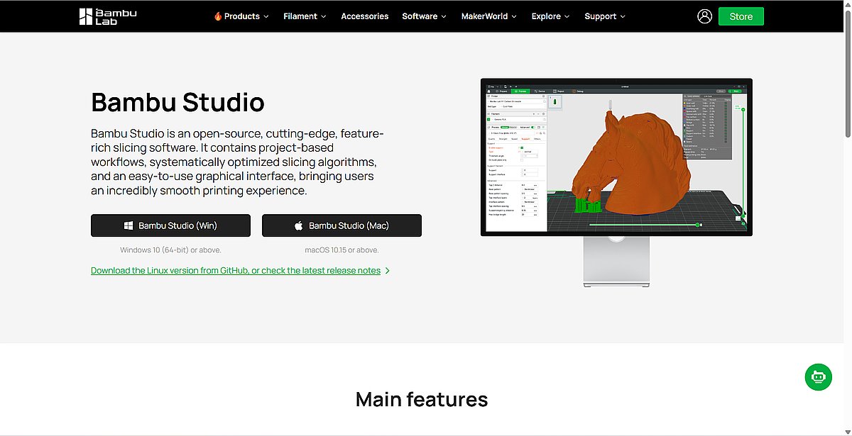
- Slicer: Bambu Studio
- 2D vector editing: Inkscape
- 3D CAD: Onshape
- Quick image conversion: ImageToSTL
- 3D scanning apps: Polycam, Luma AI
Files
- FU-Character-1.png
- Round Fu character (PNG)
- Round Fu (STL)
- Fu decoration (STL)
- Fu panel (STL)
- OLED Holder (STL, final version)
Group assignment
For group work, we tested our printer design rules: overhangs, clearances, and wall thickness. This helped me understand where the machine is reliable and where designs start to fail.
Detailed group documentation: Week 5 group assignment
Testing and recording
The printing process went smoothly:
Angle test showed some stringing and uneven surfaces at angles below 30 degrees. The 20, 10, and 0 degree overhang surfaces collapsed and could not maintain flatness.
Thickness test had three thin sections completely missing from the print, all the slots were present, but the thinnest walls simply did not appear.
Overhang test generally looks great, but the last one overhangs 10mm looks very rough.
Overhang and bridging
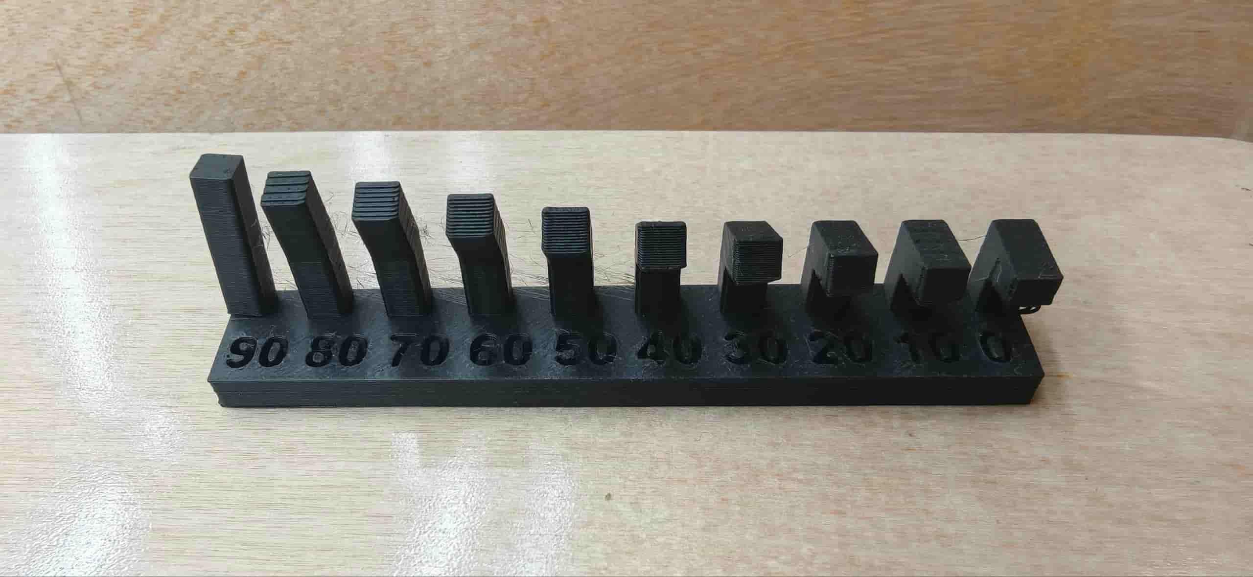
We checked the quality of different overhang angles on Angle test.
| Overhang Angle (degrees) | Overhang Surface Quality |
|---|---|
| 90 | Perfect |
| 80 | Perfect |
| 70 | Perfect |
| 60 | Perfect |
| 50 | Perfect |
| 30 | Good, slight protrusion at edges |
| 20 | Good, slight protrusion at edges |
| 10 | Noticeable stringing |
| 0 | Accumulation and uneven surface |
Wall thickness
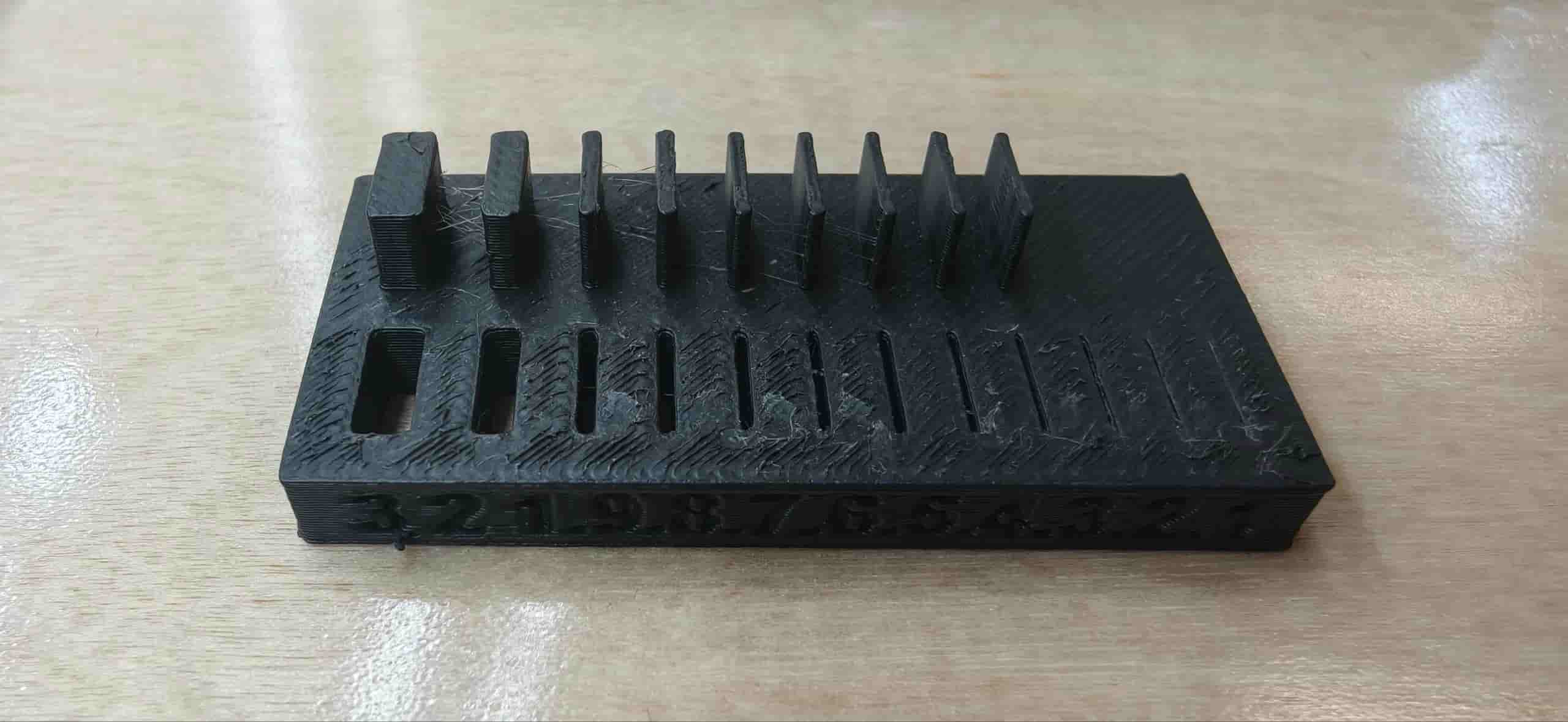
We checked the completeness of different wall thicknesses:
| Design Thickness (mm) | Actual Thickness (mm) | Deviation (mm) |
|---|---|---|
| 0.1 | Not printed | — |
| 0.2 | Not printed | — |
| 0.3 | Not printed | — |
| 0.4 | 0.5 | 0 |
| 0.5 | 0.5 | 0 |
| 0.6 | 0.6 | 0 |
| 0.7 | 0.7 | 0 |
| 0.8 | 0.8 | 0 |
| 0.9 | 0.9 | 0 |
| 1 | 1 | 0 |
| 2 | 2 | 0 |
| 3 | 3 | 0 |
The 0.1–0.3 mm walls were ignored entirely during slicing and never appeared on the print. From 0.4 mm upward, the results were very close to the design, with only a small 0.1 mm deviation at 0.4 mm.
Overhang distance test
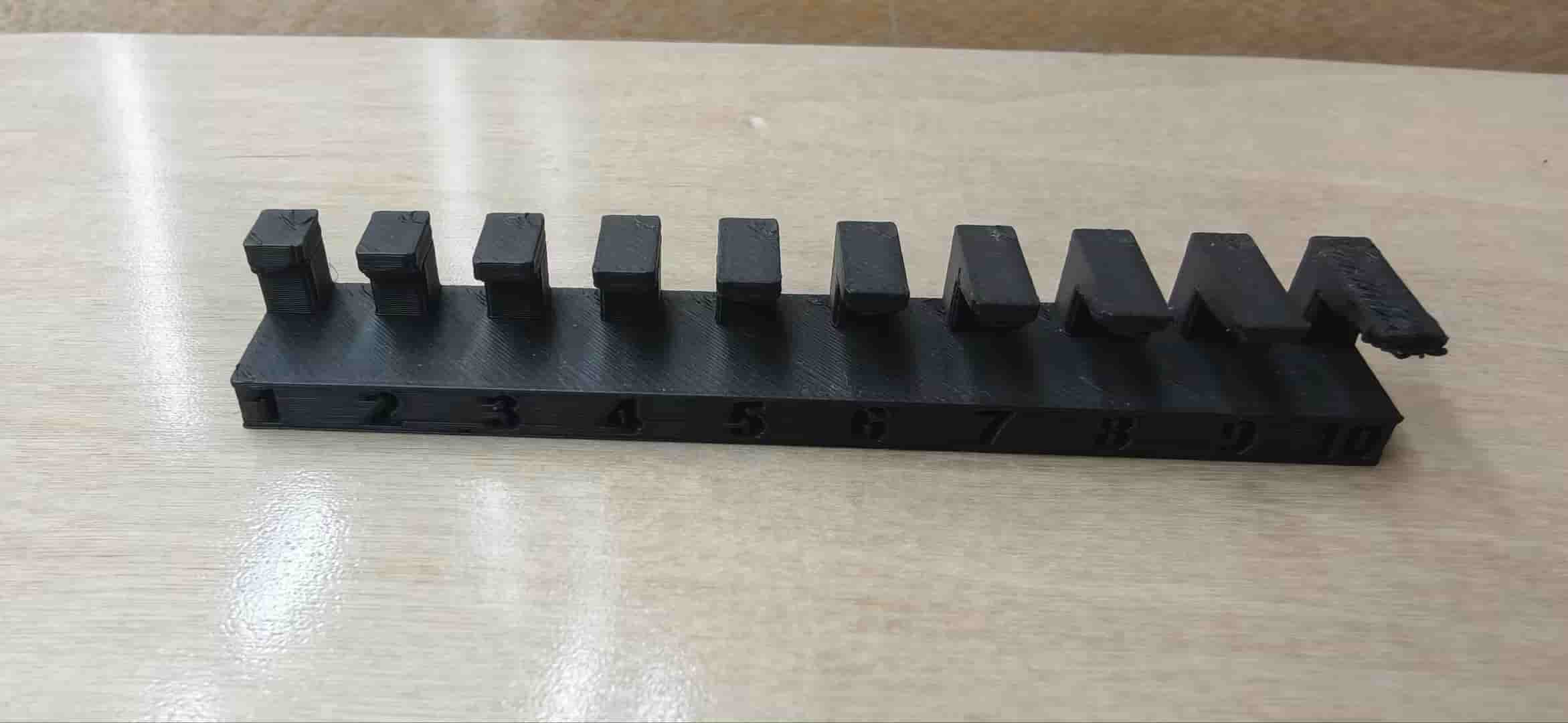
We checked how the printer handles increasing overhang distances — how far a section can extend horizontally without support before the quality breaks down.
| Overhang Distance (mm) | Surface Quality |
|---|---|
| 1 | Fine |
| 2 | Fine |
| 3 | Fine |
| 4 | Fine |
| 5 | Fine |
| 6 | Fine |
| 7 | Slightly rough |
| 8 | Slightly rough |
| 9 | Very rough |
| 10 | Very rough |
Up to 1 mm, the overhang still looked clean. From 2–5 mm, the surface got a bit rough but held its shape. From 6 mm onward, the print couldn't bridge the gap properly, lots of drooping and stringing.
What we learned
Through this test, we got a clearer picture of the Bambu Lab A1 mini's real-world limits with PLA:
- Overhang angles of 30° and above print reliably. Below 30°, expect stringing or surface collapse.
- Wall thicknesses below 0.4 mm are too thin to print — the slicer skips them entirely.
- Overhang distances up to 1 mm print cleanly. From 2–5 mm, expect some surface roughness. Beyond 6 mm, stringing and spaghetti become a real problem without supports.
- First layer adhesion was solid for both test models.
These numbers give me a practical reference for my own designs. If I'm designing something with fine details, I now know to keep walls above 0.4 mm and avoid unsupported overhangs longer than 5 mm.
Individual Assignment: from 2D Fu to 3D print
I decided to try two workflows and three print iterations:
- A quick "just print it first" workflow.
- A more controlled workflow with vector cleanup and CAD modeling.
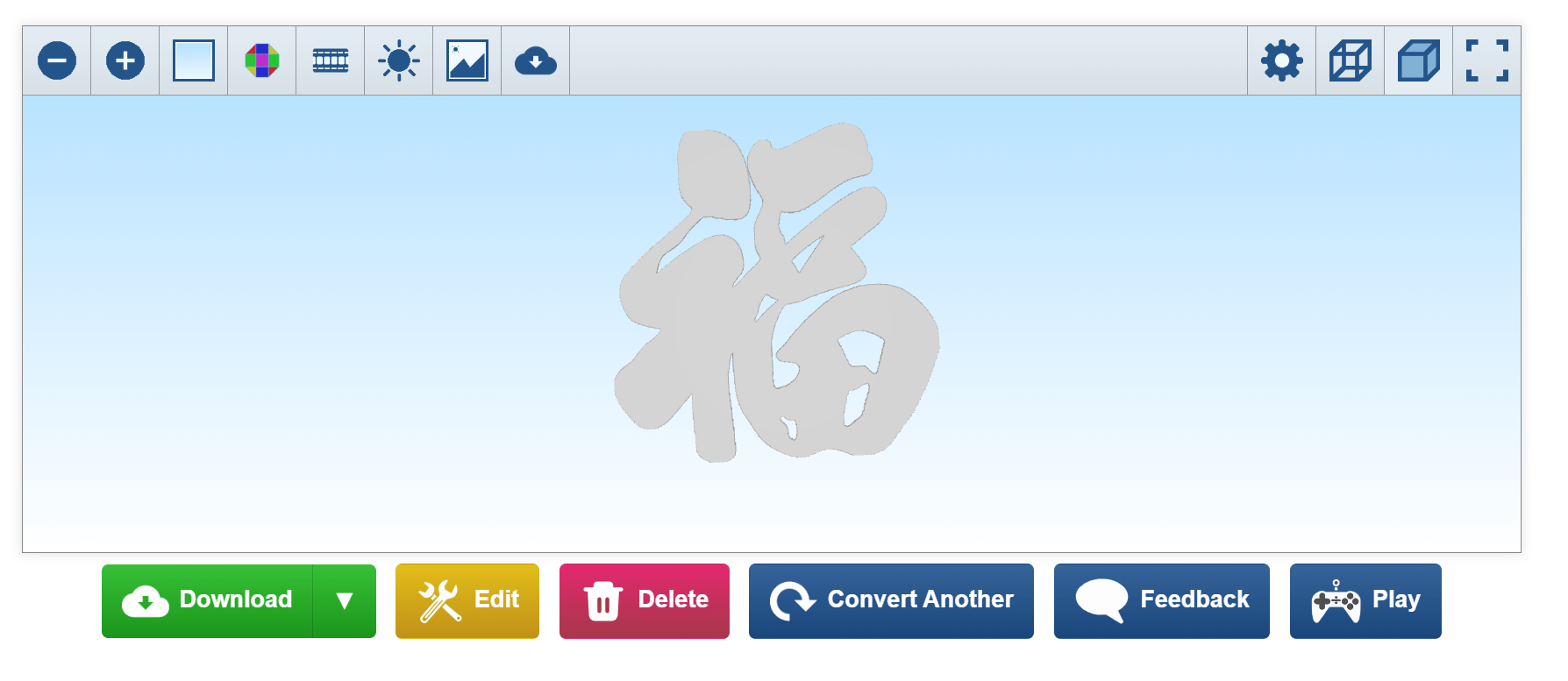
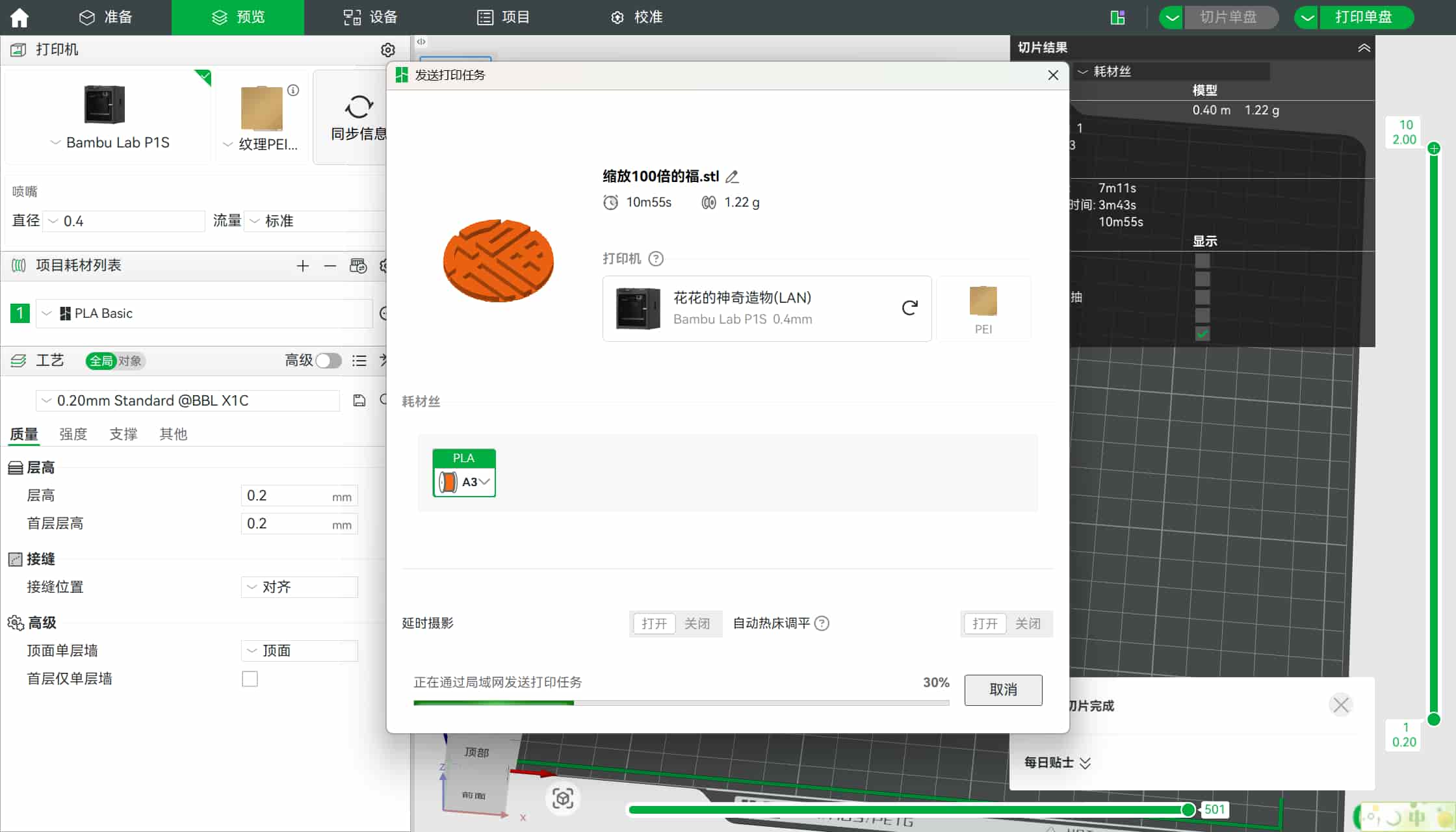
First attempt: quick test with ImageToSTL
I began with a high-contrast Fu image from the web and uploaded it to ImageToSTL.
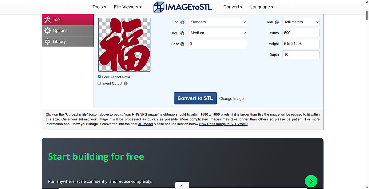
- The platform generated an STL automatically from image contrast.
- In the converter, I set the thickness around 20 mm in the Z direction, but this first run was still a practical thin test after slicing and scaling.
- I registered and prepared the file in Bambu Studio.
- The initial scale was too large for the machine, so I resized it to fit the A1 mini's build area.
- I connected to the A1 mini over Wi-Fi (IP + pairing code) and sent the sliced file wirelessly.
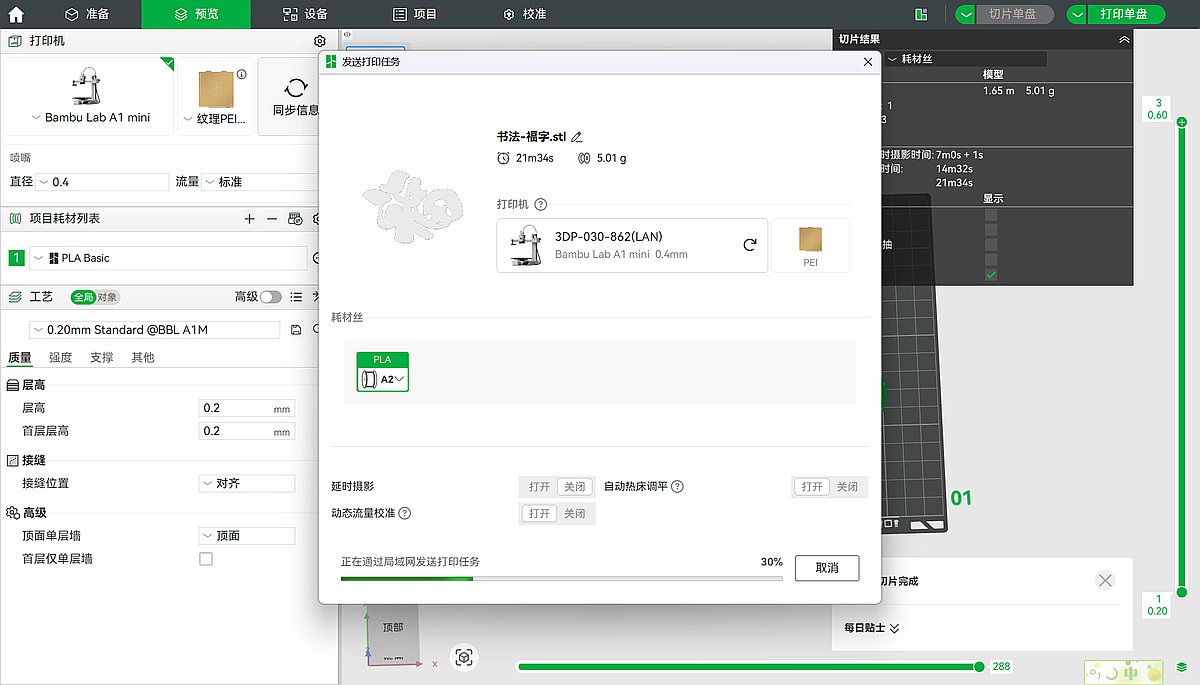
- I kept this run simple with basic PLA settings, no advanced supports, and no multi-color features, because my goal was to test behavior quickly.
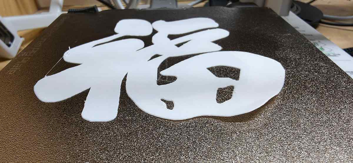
I am not suppose to design a sticker, but it looks good, thin and flexible and light, almost feel like a paper.
That first print still helped a lot: it quickly told me the visual direction works, and it looks very smooth, the material looks good.
Second attempt: Inkscape + Onshape for full control
After that, I switched to a cleaner workflow so I could control the structure.
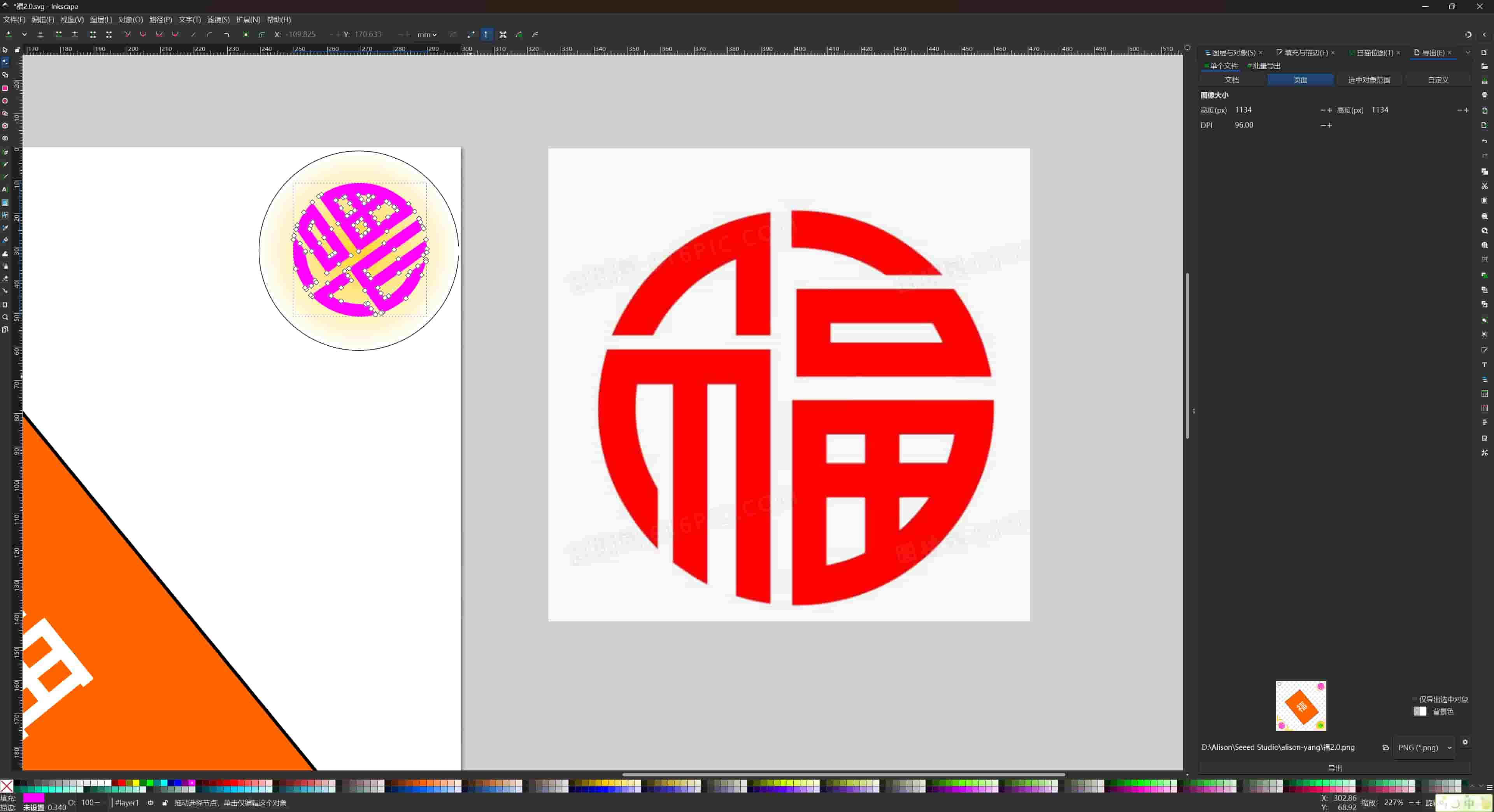
Step 1: prepare vector in Inkscape
- I imported the Fu image and used Trace Bitmap.
- I cleaned the nodes and connected anchor points.
- I used Union to make sure the design became one closed path.
- Then I exported the vector for CAD use (SVG/DXF workflow).
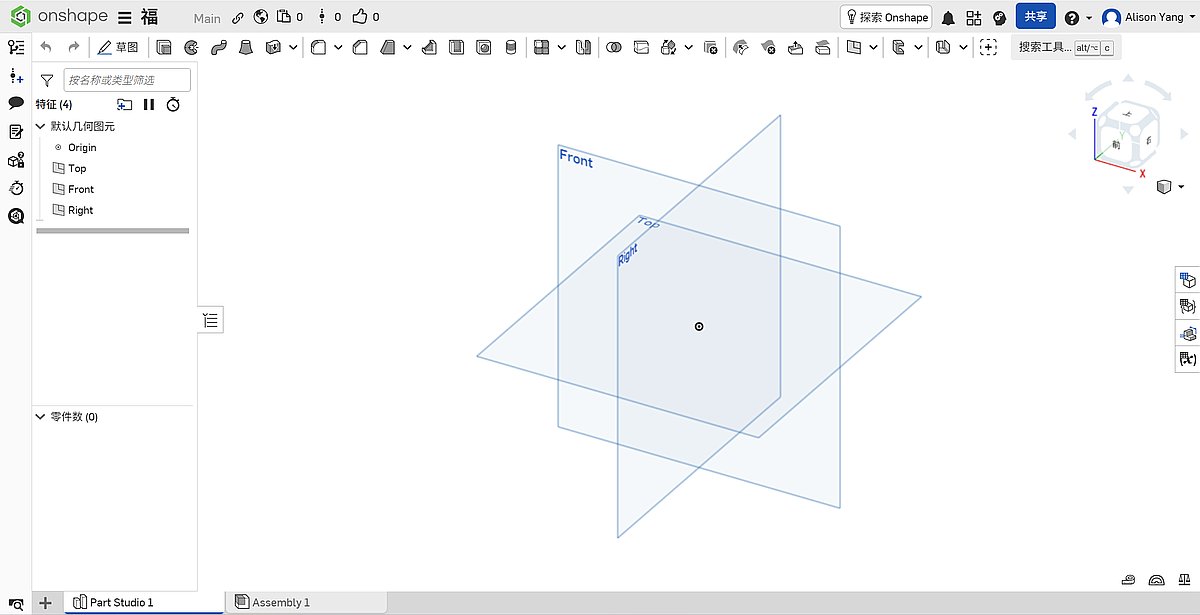
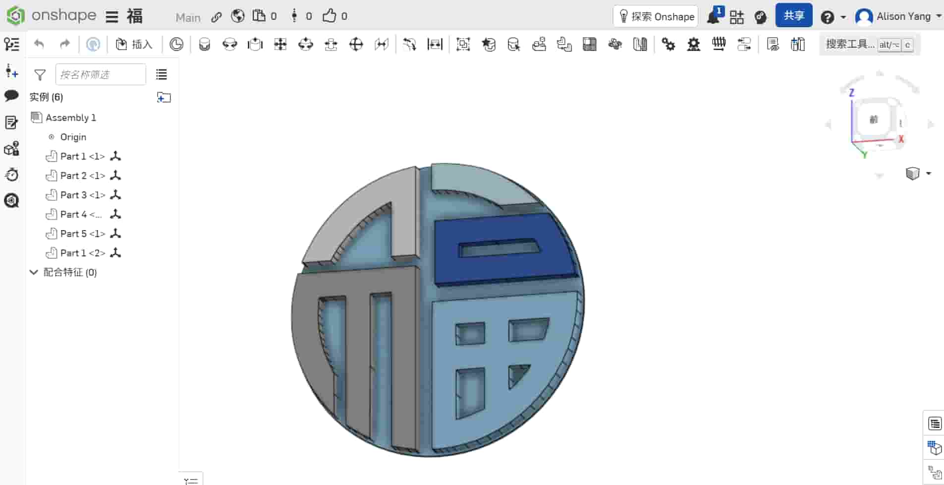
Step 2: build 3D model in Onshape
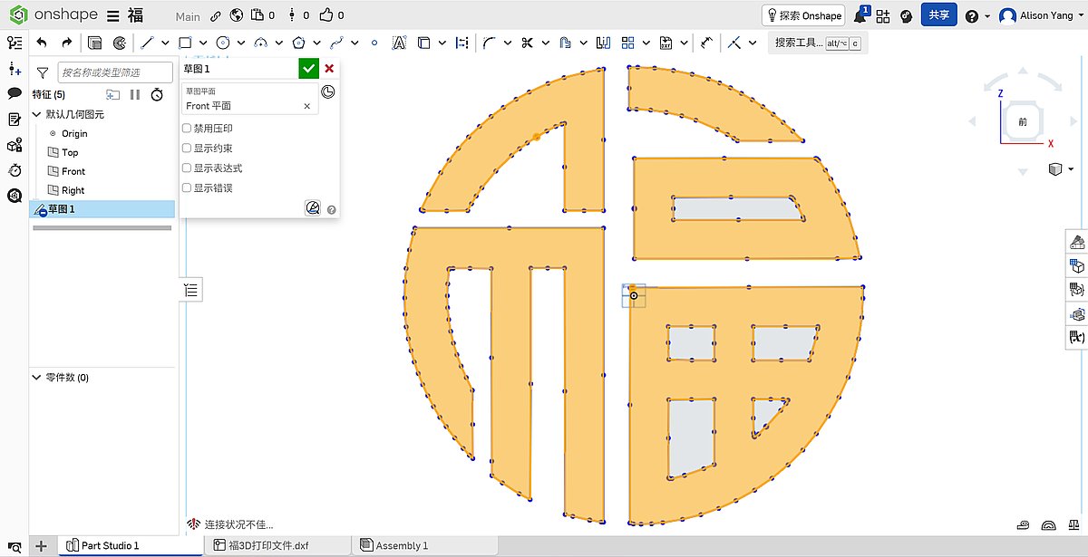
- I imported the vector onto a sketch plane in Onshape.
- I scaled and positioned the shape.
- I extruded 3mm to give it thickness and generate a solid body.
- I chose this method because a parametric model is easier to adjust later for my "smart Fu" version (for example: thickness updates, back plate, electronics-related structure).
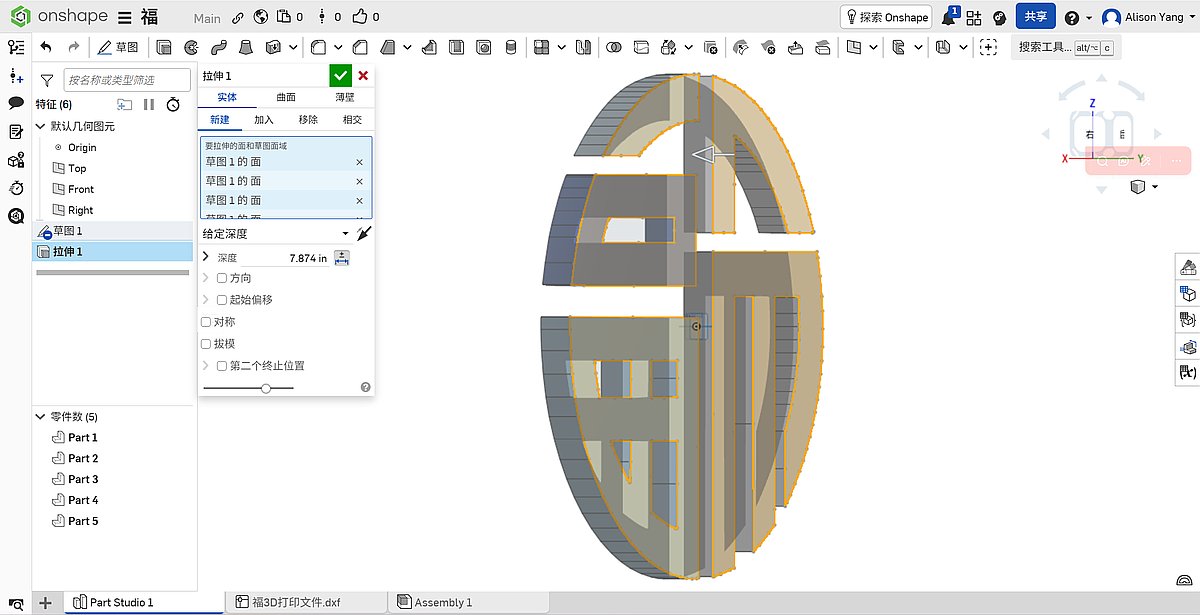
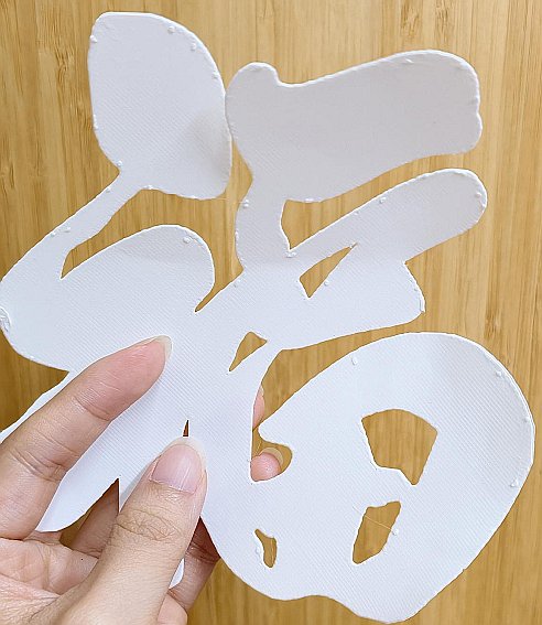
Step 3: the failure I almost missed
In this version, I increased thickness but forgot to create one continuous backing layer behind the strokes.
The print came out as separated parts, not one integrated decoration.
When I looked back, the issue was already visible in preview, but I did not catch it before printing.
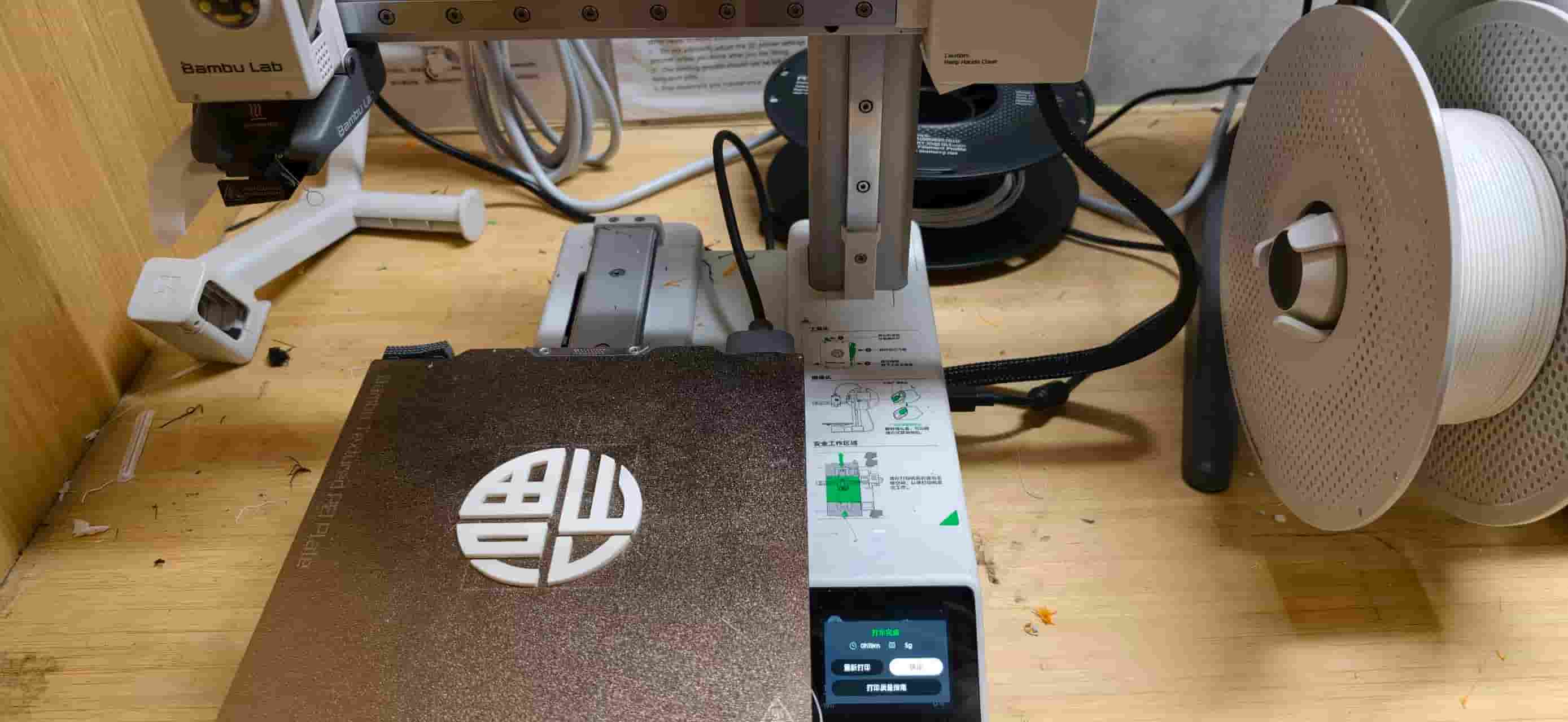
Step 4: redesign and final successful print
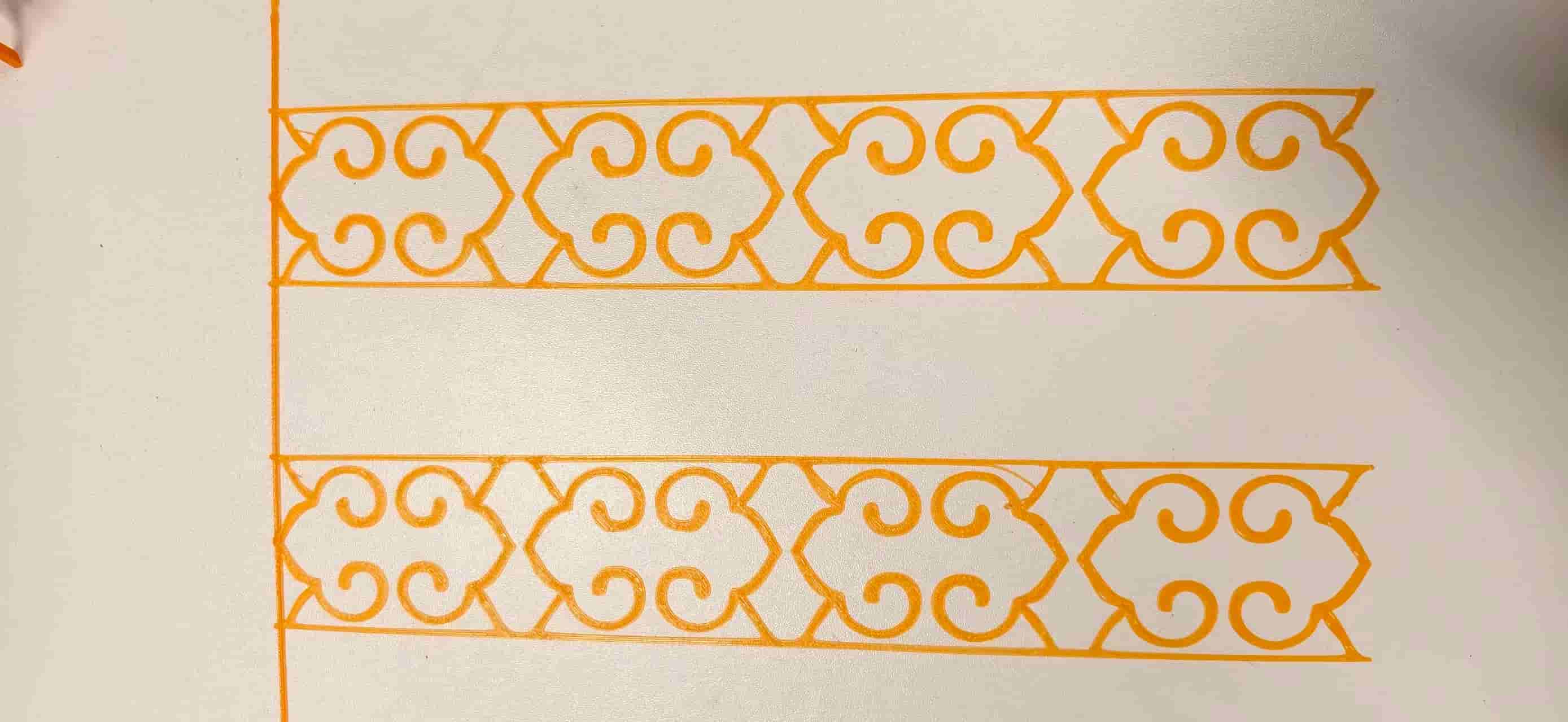
I redesigned the pattern again and added a solid base plate under the Fu character.
I also tested orange filament to make the pattern more vivid and easier to read visually.
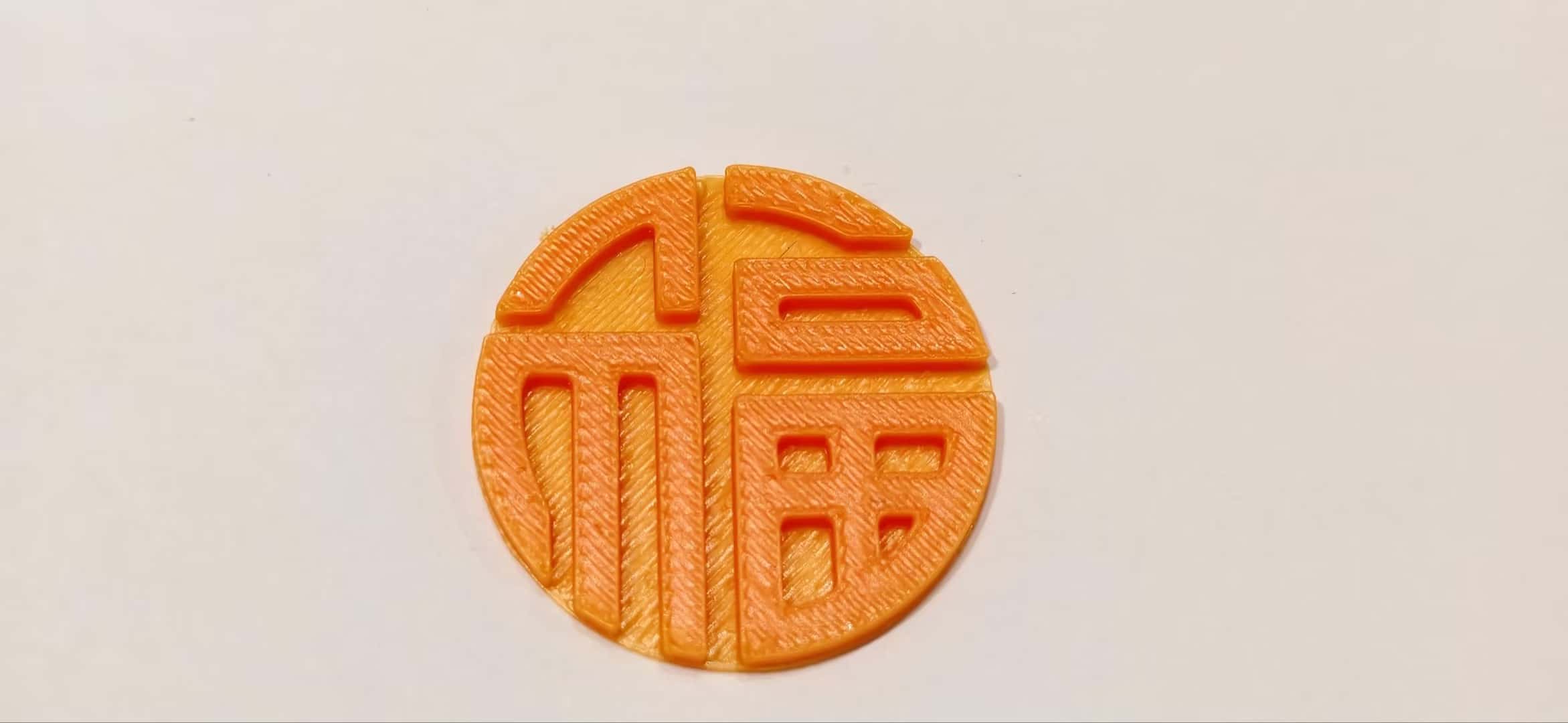
This time, the print came out as one complete piece, with much better strength and a cleaner finish. Looks very nice:D
What changed between attempts
- Attempt 1 (quick STL conversion): visually clear, but too thin and flexible.
- Attempt 2 (parametric model without full backing): thicker, but disconnected geometry and failed as a single rigid object.
- Attempt 3 (parametric model + solid base layer): structurally connected, successful one-piece print.
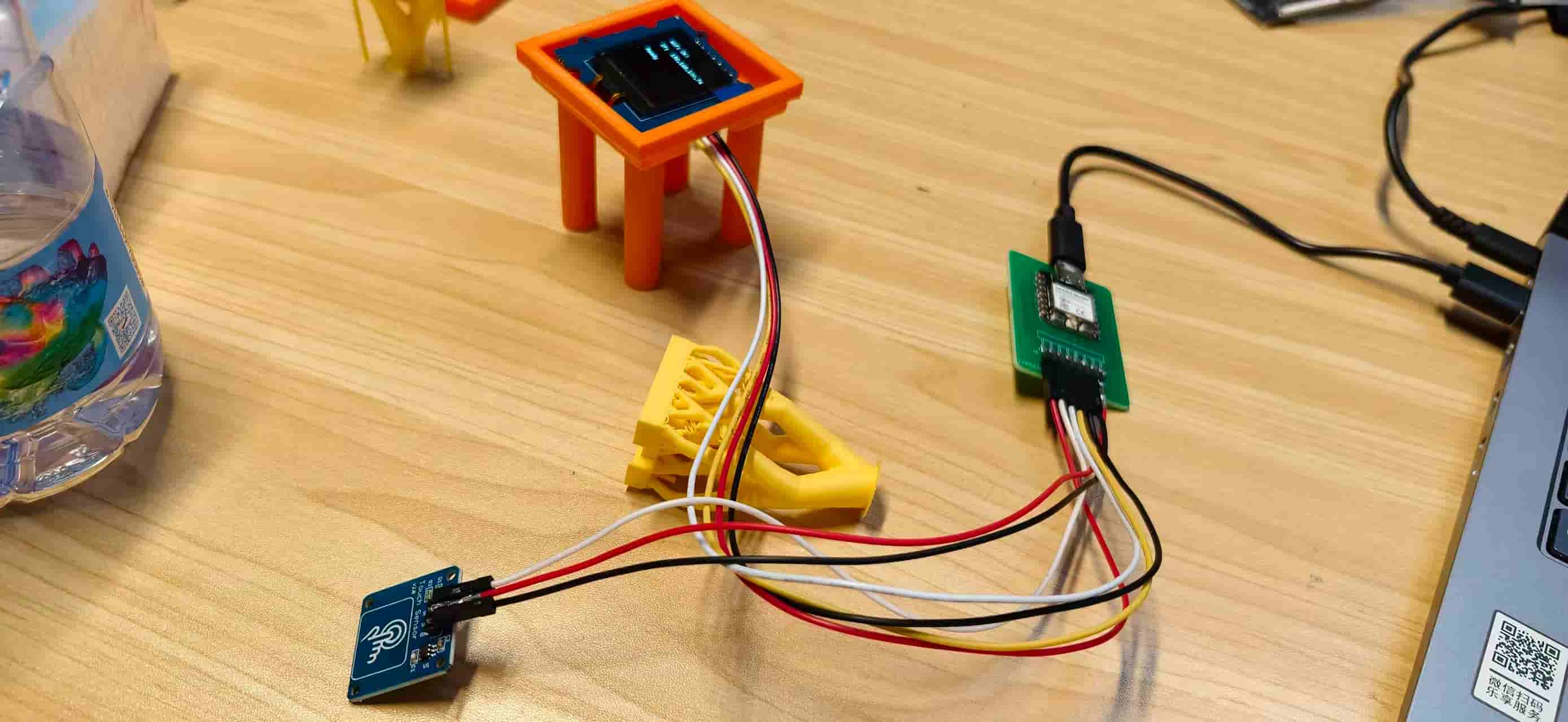
OLED Holder
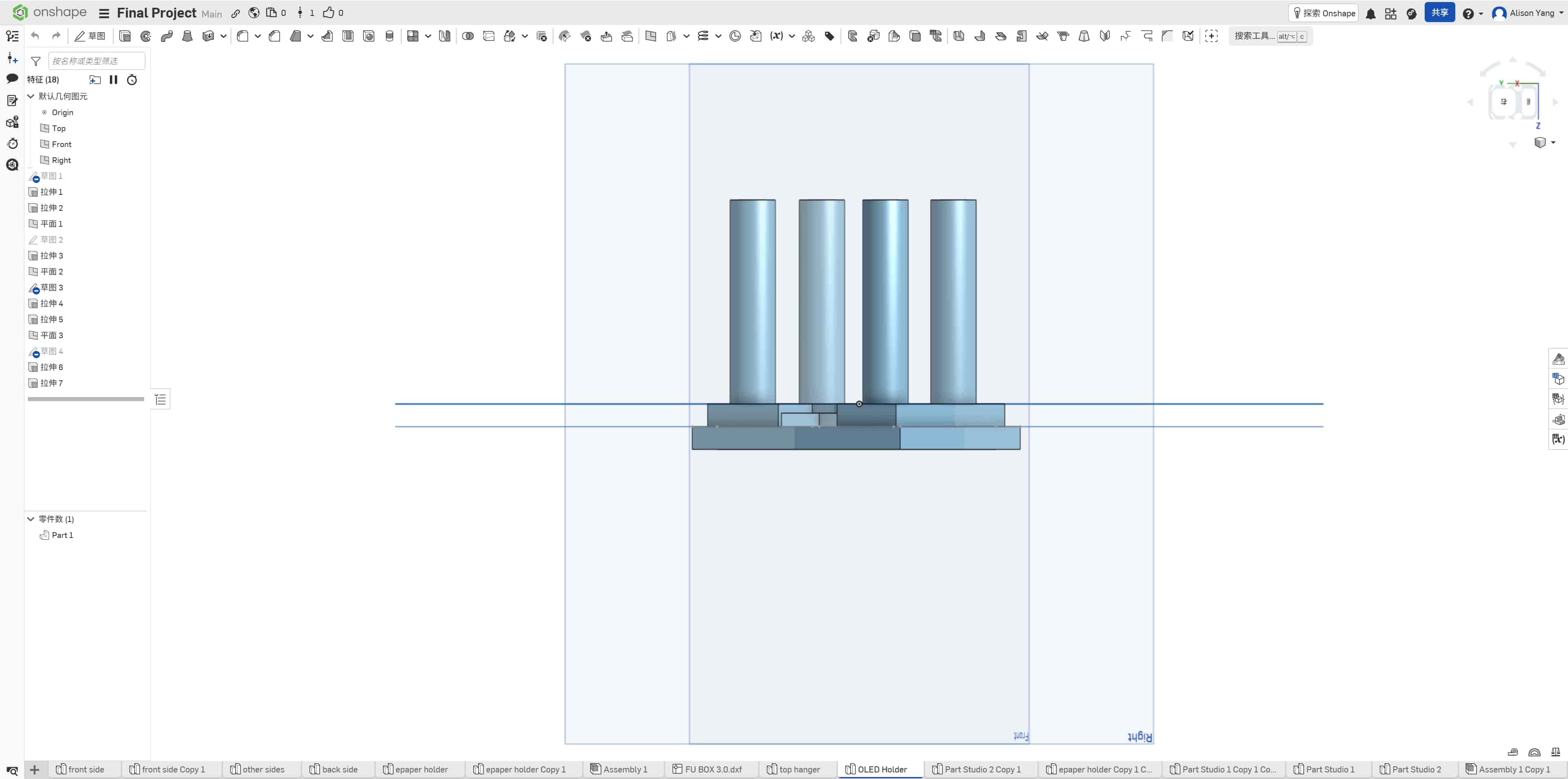
I modeled an OLED holder in Onshape for my Smart Fu final project. The part mounts a Grove 128×128 OLED display inside a laser-cut wooden enclosure while routing its fragile ribbon cable safely through the structure.
Unlike the Fu decoration (essentially a 2D extrusion), this holder combines two stepped frame layers, a center base with a wiring cutout, and four long vertical pillars in one monolithic print. That geometry is what makes it a stronger answer to the assignment brief.
Design Specifications
The holder uses a stepped frame structure designed to snap into a laser-cut wooden board. All geometry is defined parametrically in Onshape.
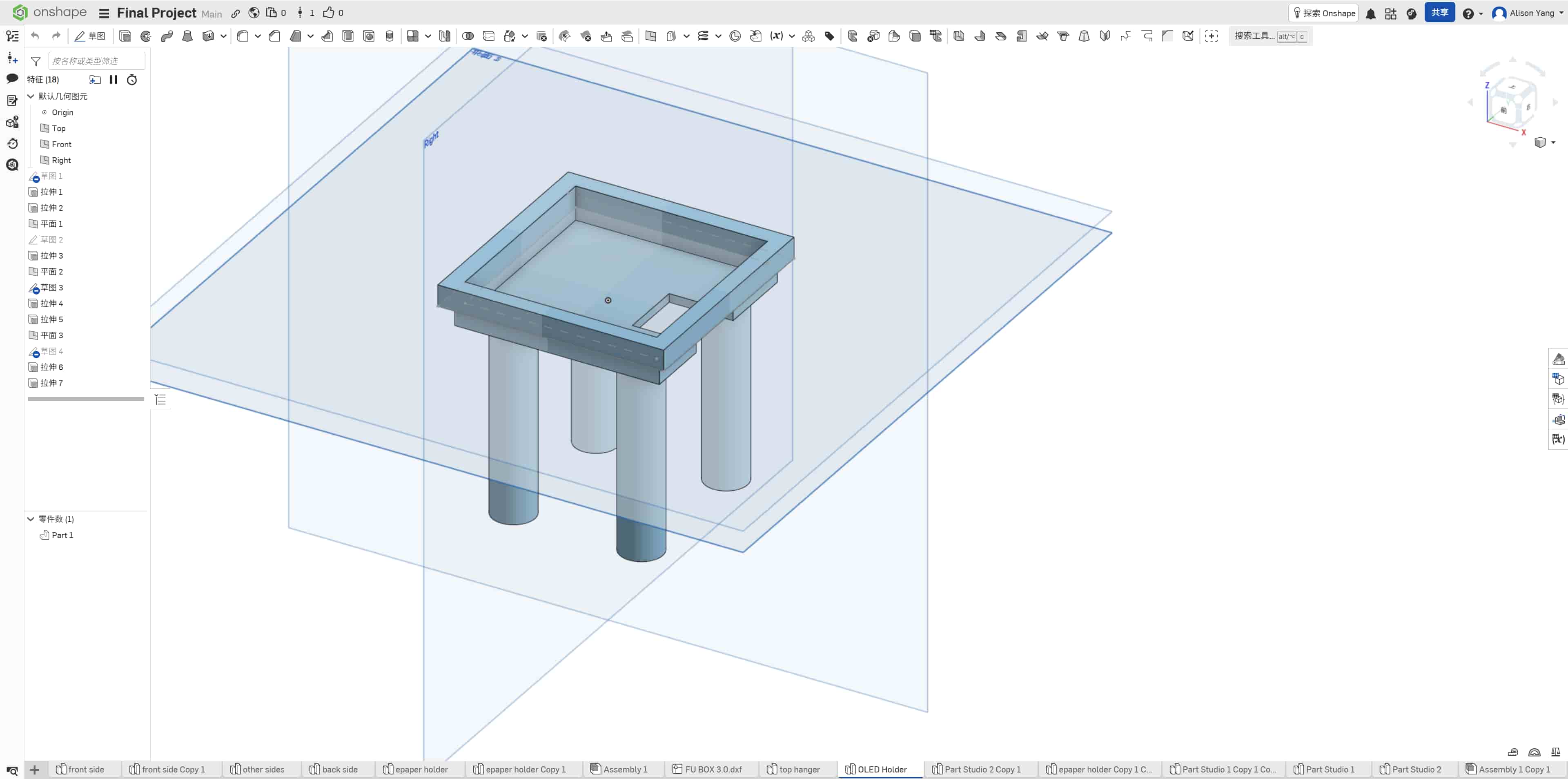
Stepped frame structure
Two square frame layers stack to form the snap-fit interface with the enclosure panel. Each frame is 5 mm thick, matching the thickness of the laser-cut plywood so the holder sits flush with the wooden surface.
| Layer | Type | Inner size | Outer size | Thickness | Role |
|---|---|---|---|---|---|
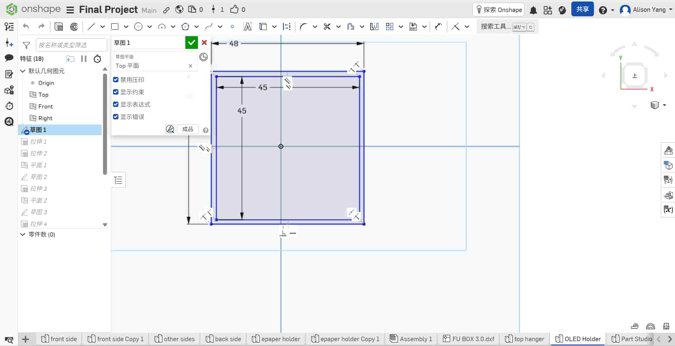
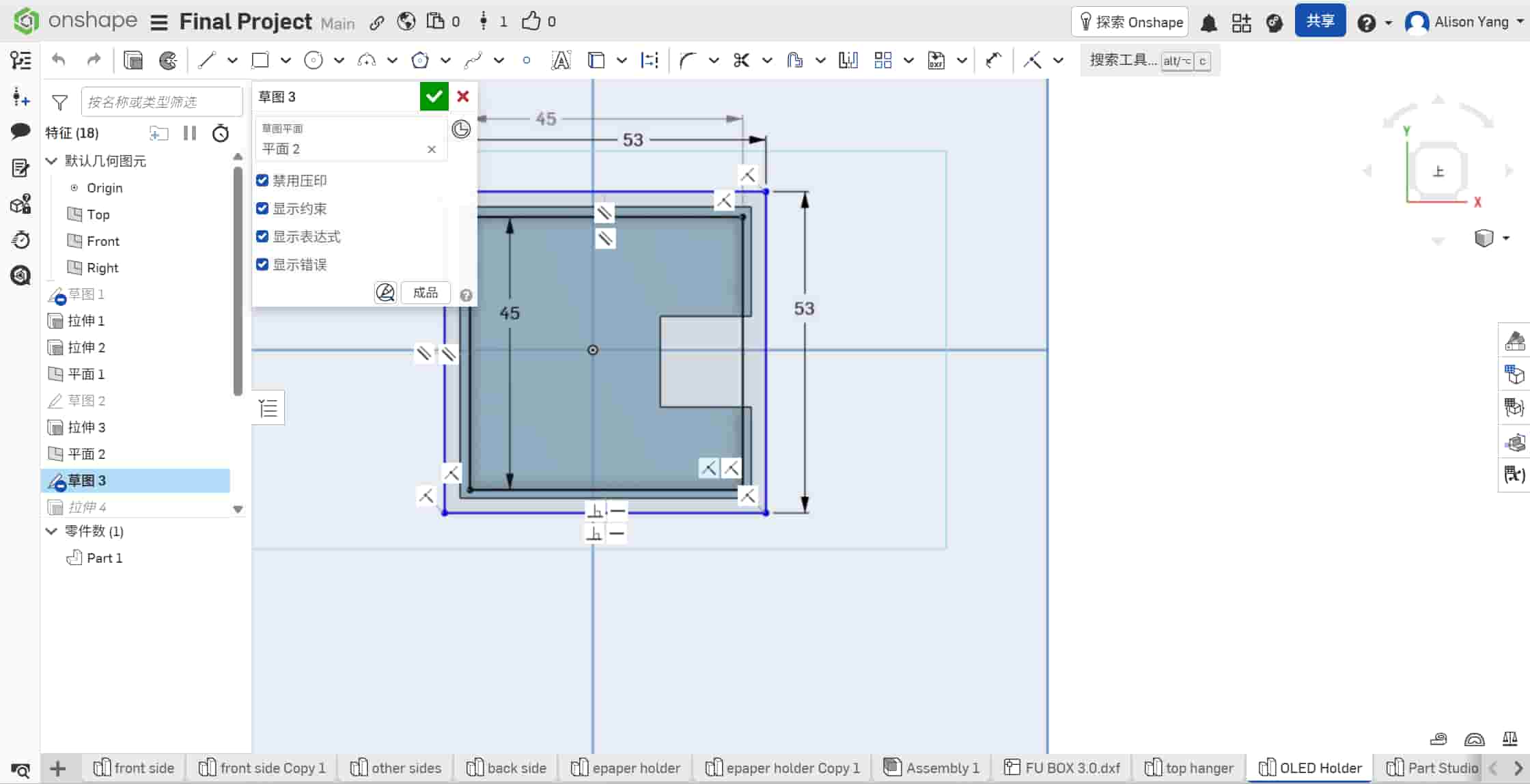
| Layer 1 | Top flange | 48 mm × 48 mm | 53 mm × 53 mm | 5 mm | Rests on the panel surface; retains the holder in the opening |
| Layer 2 | Alignment step | 45 mm × 45 mm | 48 mm × 48 mm | 5 mm | Drops into the laser-cut slot; aligns the holder vertically |
The dimensioned sketches in Onshape confirm the 45 mm / 48 mm and 53 mm / 48 mm frame sizes:
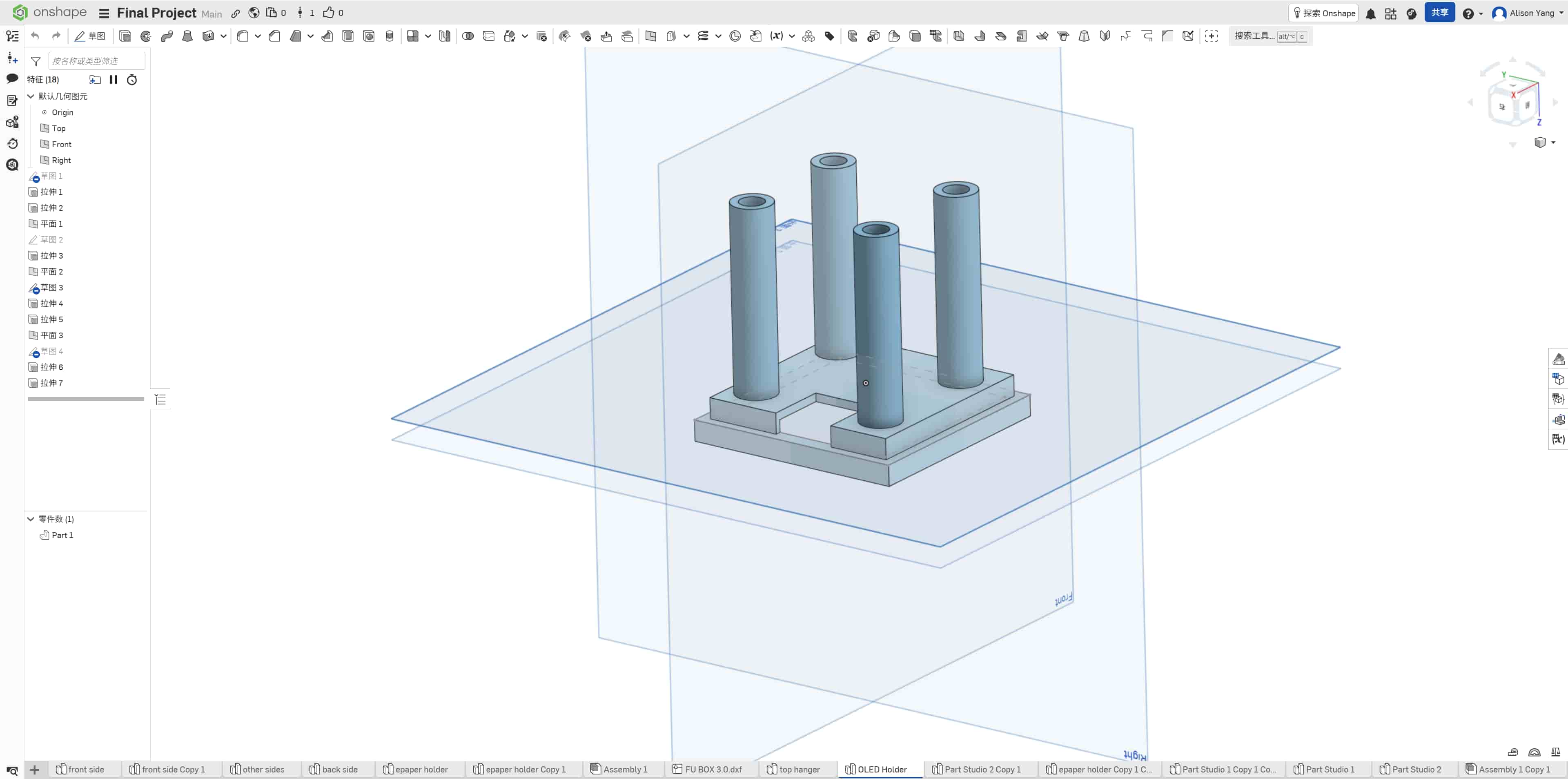
Center base
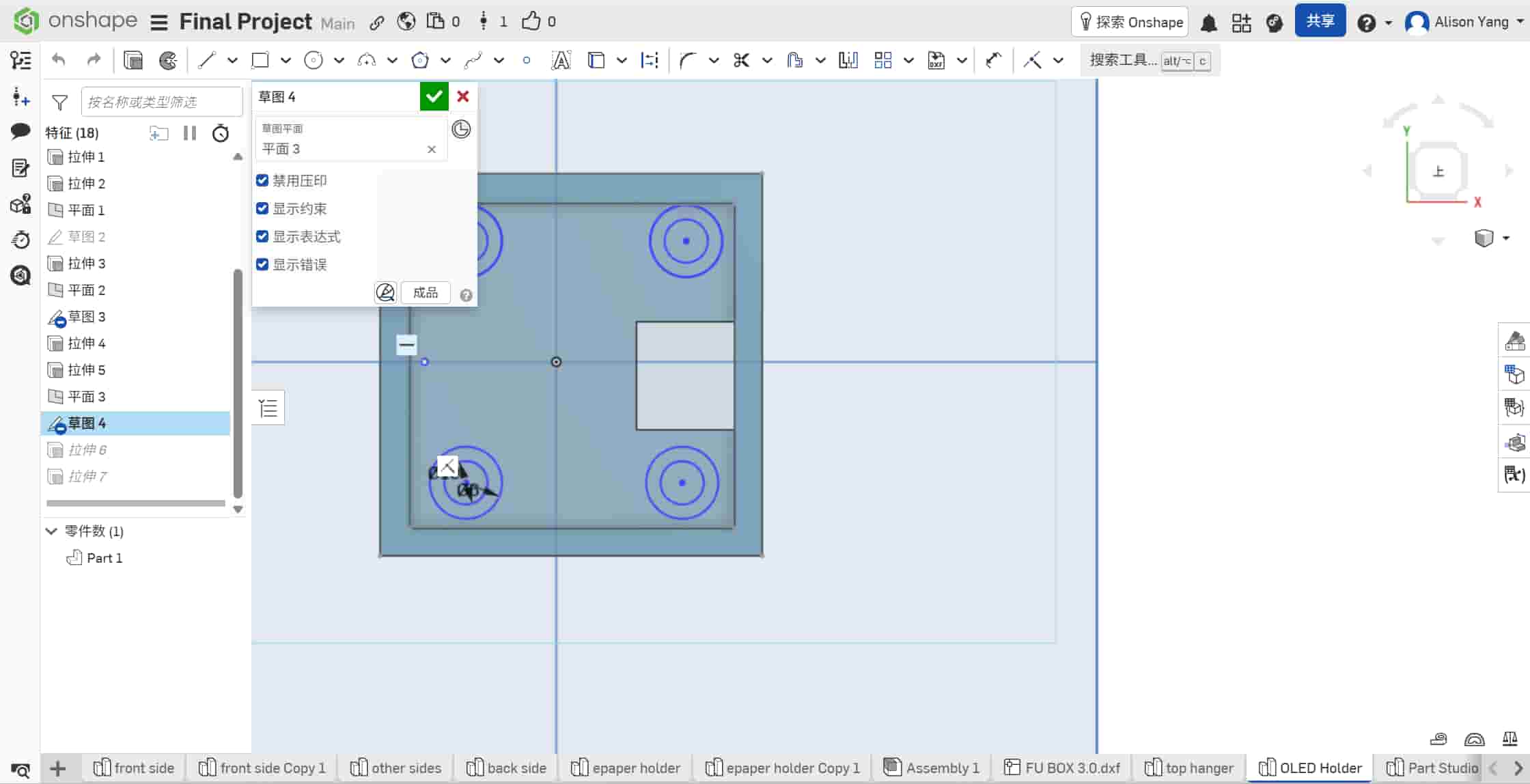
A 45 mm × 45 mm central platform sits inside the stepped frames. A 15 mm × 15 mm square cutout in the middle of this platform routes the fragile OLED ribbon cable and connector through the holder without sharp bends against the wood edge.
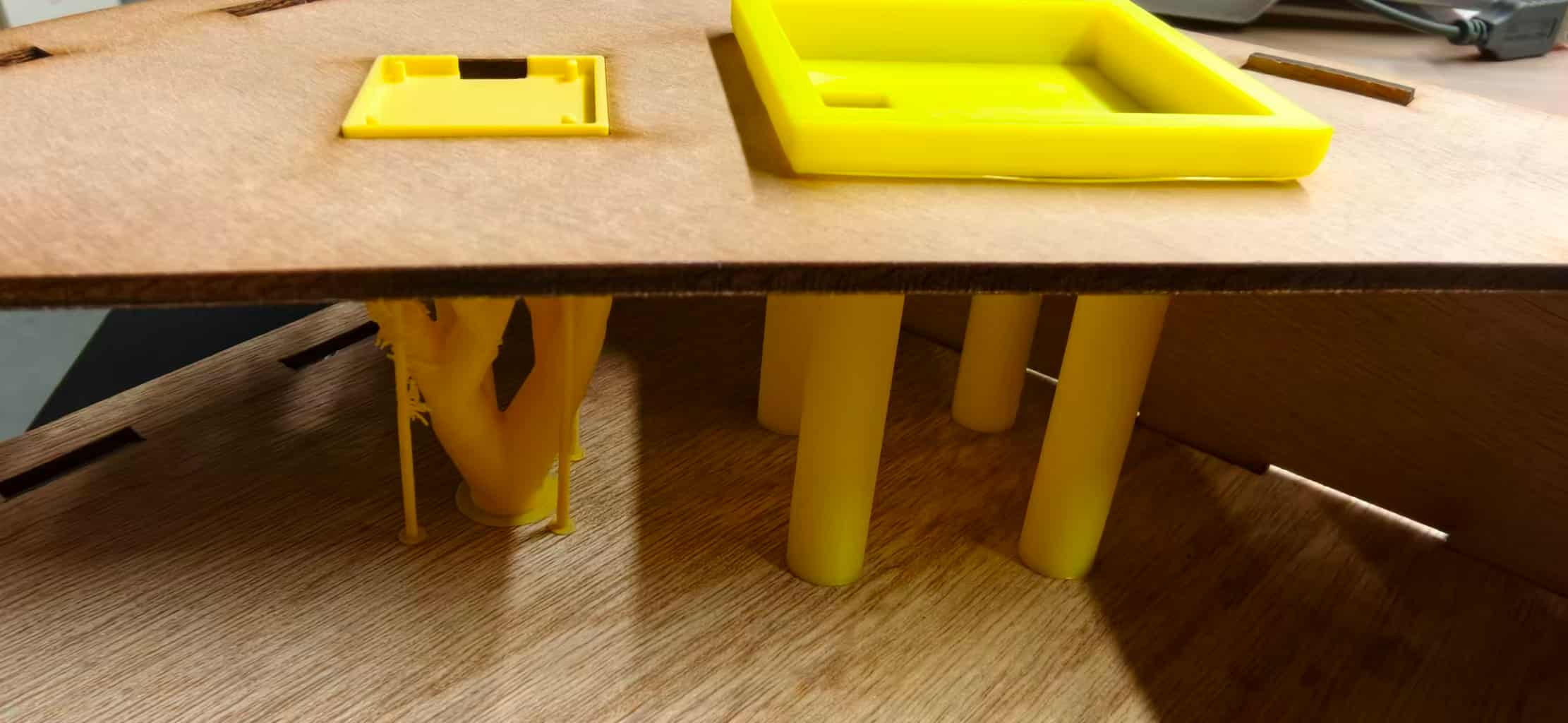
Support pillars
Four cylindrical pillars, each 45 mm in height, are extruded downward from the corners of the center base. They act as the mounting legs inside the enclosure,lifting the display platform to the correct height while leaving open space below for cable routing and the ESP32 board.
| Feature | Dimension |
|---|---|
| Layer 1 — top flange | 48 mm × 48 mm (inner) → 53 mm × 53 mm (outer), 5 mm thick |
| Layer 2 — alignment step | 45 mm × 45 mm (inner) → 48 mm × 48 mm (outer), 5 mm thick |
| Center base | 45 mm × 45 mm platform |
| Wiring cutout | 15 mm × 15 mm (through center base) |
| Support pillars | 4 × cylinders, 45 mm height |
| Total frame stack height | 10 mm (2 × 5 mm stepped frames) |
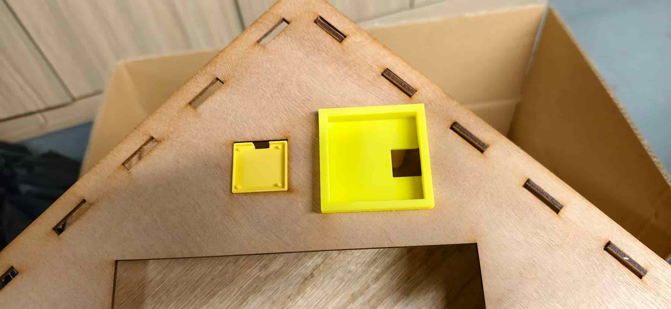
Integration with Enclosure
The holder is designed to mate with a 5 mm thick laser-cut wooden panel. The two stepped frames work together as a mechanical socket:
- A 48 mm × 48 mm square opening is cut in the wood panel.
- Layer 2 (alignment step) drops into that opening,its 48 mm outer edge matches the slot, and its 5 mm thickness fills the panel depth.
- Layer 1 (top flange) rests flush on the panel surface. Its 53 mm outer edge overhangs the opening and prevents the holder from falling through.
- The 45 mm × 45 mm center base and 15 mm wiring cutout sit above the panel, ready to receive the OLED module.
- The four 45 mm pillars extend below the panel into the enclosure interior, providing vertical support without glue.
Because each frame layer is exactly 5 mm thick, the alignment step fills the full thickness of a standard 5 mm plywood slot. The top flange then sits level with the wooden surface, the OLED bezel is flush rather than floating above or sinking below the panel.
This snap-fit approach also keeps the enclosure serviceable. The holder can be removed for debugging without destroying the wooden frame,an important constraint for a project that still needed firmware iteration.
3D Printing Justification
The holder combines a wide overhanging top flange (53 mm outer span) with four long, thin vertical pillars (45 mm tall) in a single monolithic piece. Machining this from a solid block would require removing a massive amount of empty space,the volume between the four pillars, beneath the stepped frame pockets, and inside the 15 mm wiring cutout would all become waste chips.
It would also require multi-axis flipping: one setup to machine the top stepped pocket and center cutout from above, and a separate setup to reach the underside and form the four pillars. A 5-axis machine could reduce the number of flips, but that adds cost and complexity far beyond what this small functional bracket needs.
With FDM 3D printing, the part builds bottom-up — pillars first, then the center base, then the stepped frames — depositing material only where the structure exists. The slicer adds tree supports under the overhanging top flange, but the overall material use stays far lower than starting from a solid stock block.
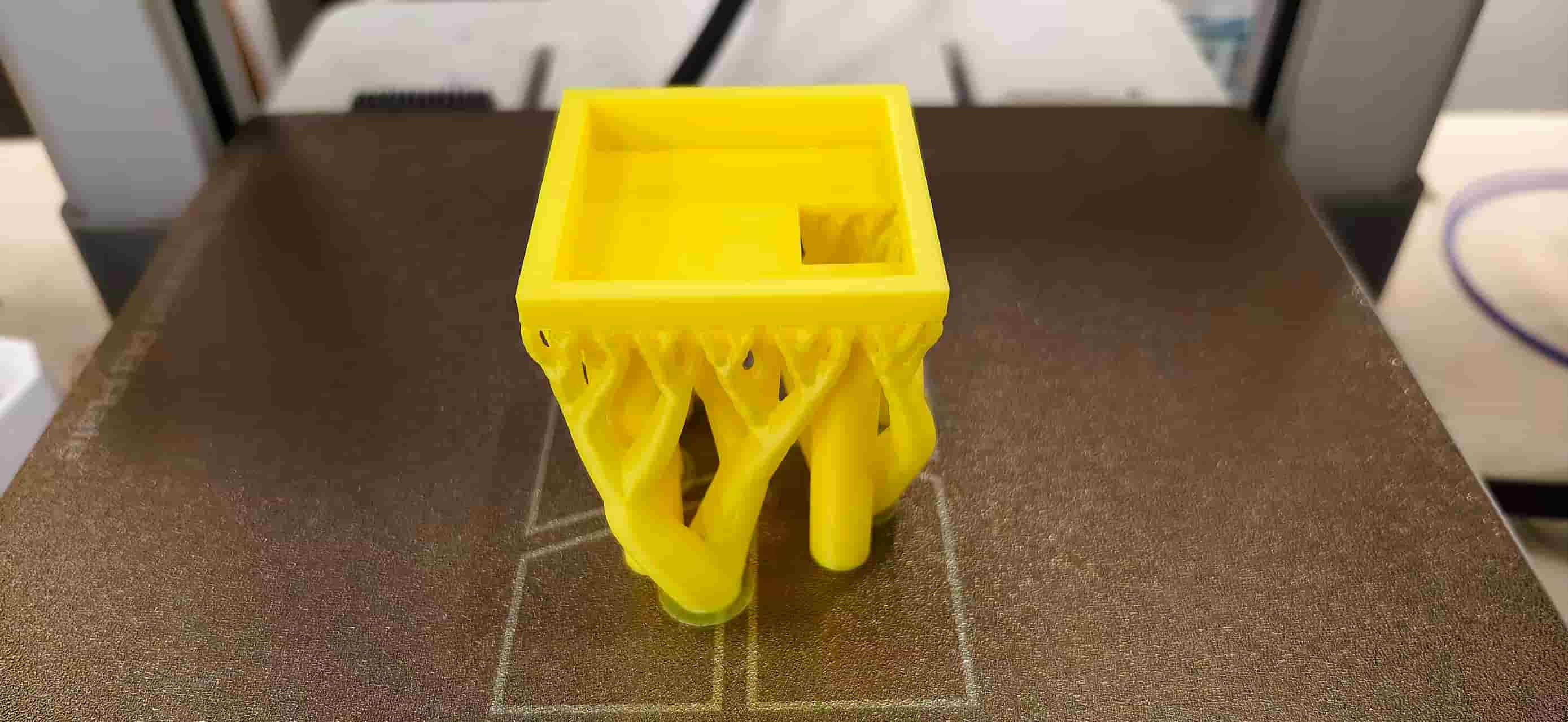
In short: the OLED holder is not just a bracket — it is a structural interface between a 2D laser-cut panel and a 3D electronics stack. Additive manufacturing builds this complex monolithic geometry layer by layer; subtractive manufacturing would fight against it at every step.
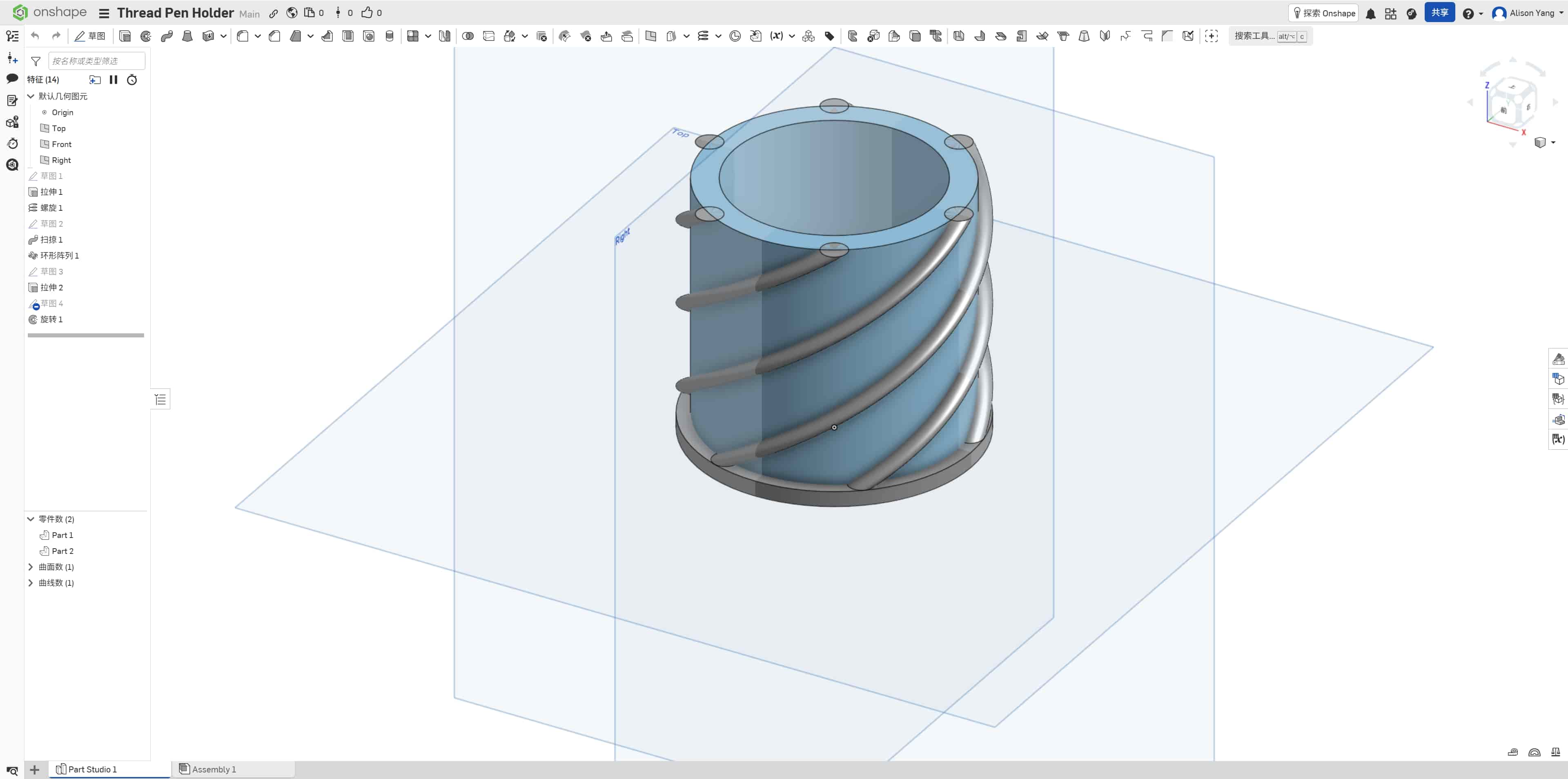
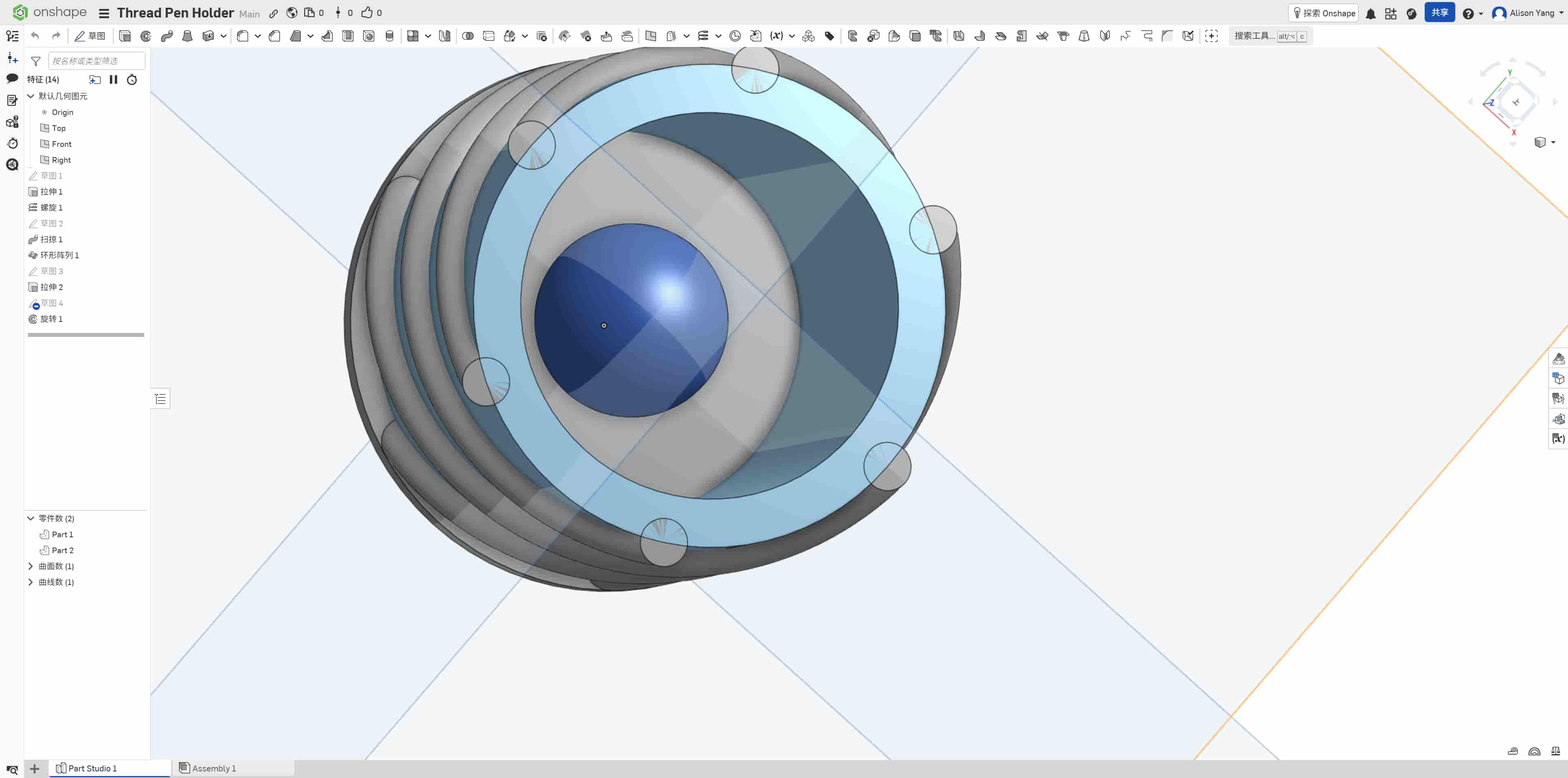
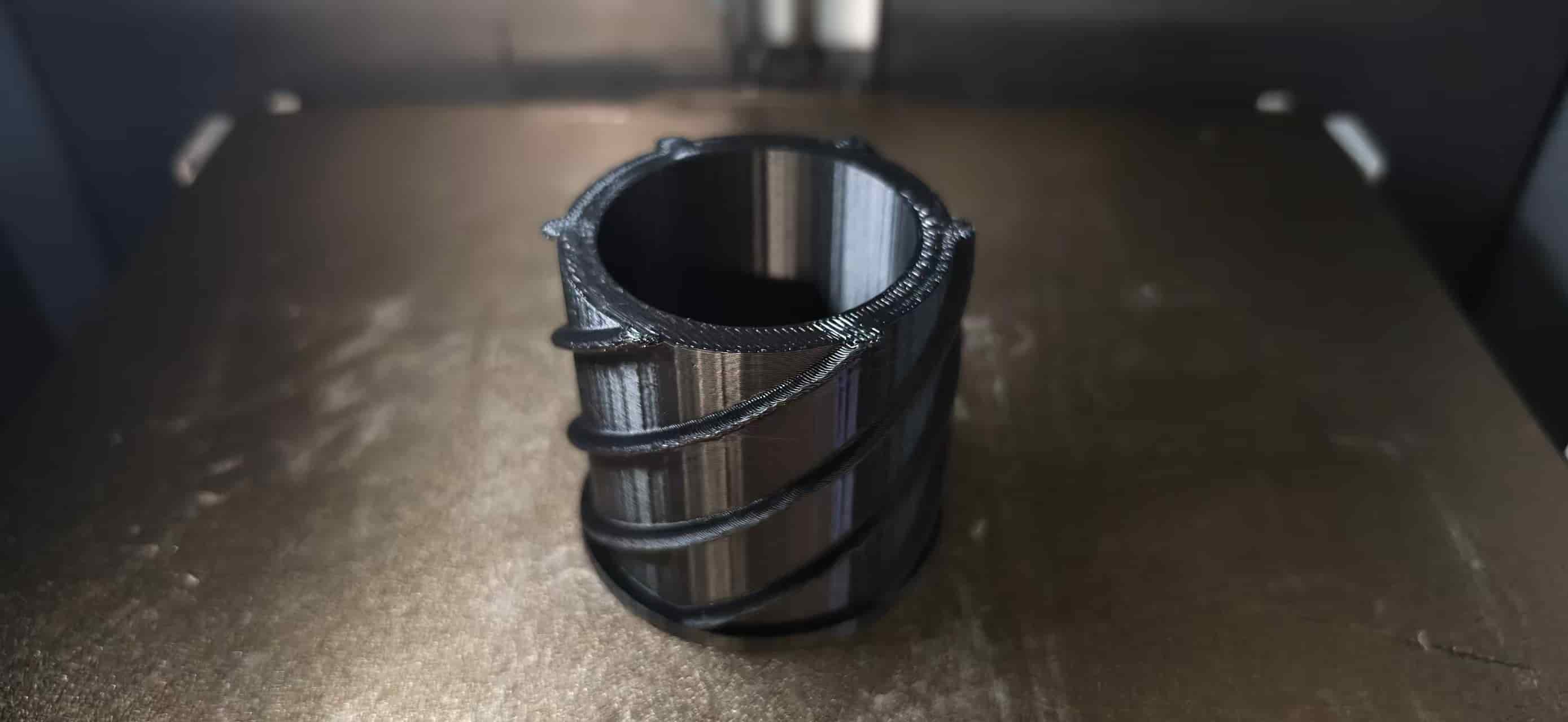
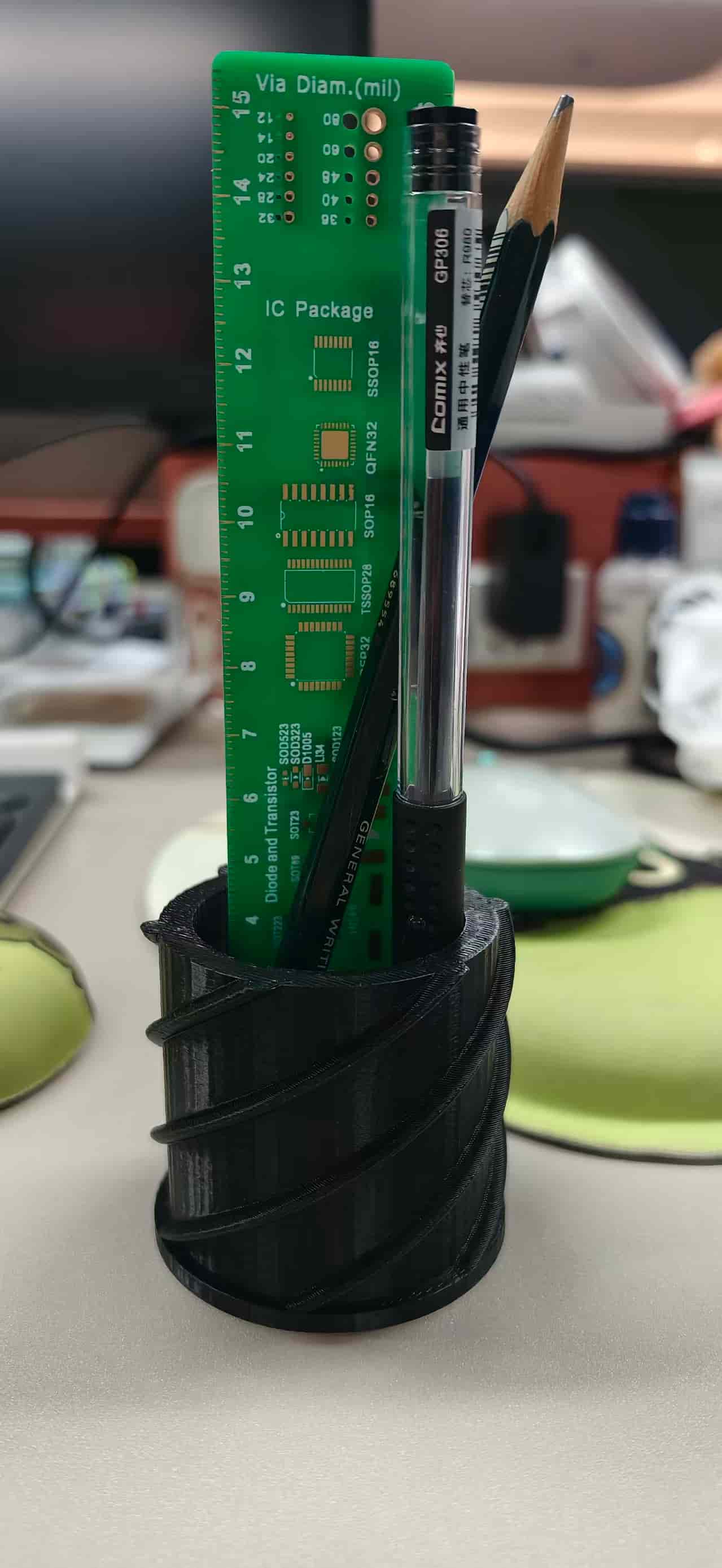
Another interesting design: Thread Pen Holder (Onshape)
I realized my desk lacking a pen holder, so I designed a model: Thread Pen Holder. This version is intentionally built around trapped geometry and complex surfaces, so the "additive advantage" is not just theoretical, it is the core of the design.
Design overview
- Form: A cylindrical pen holder body with external helical threads wrapping around the outer wall.
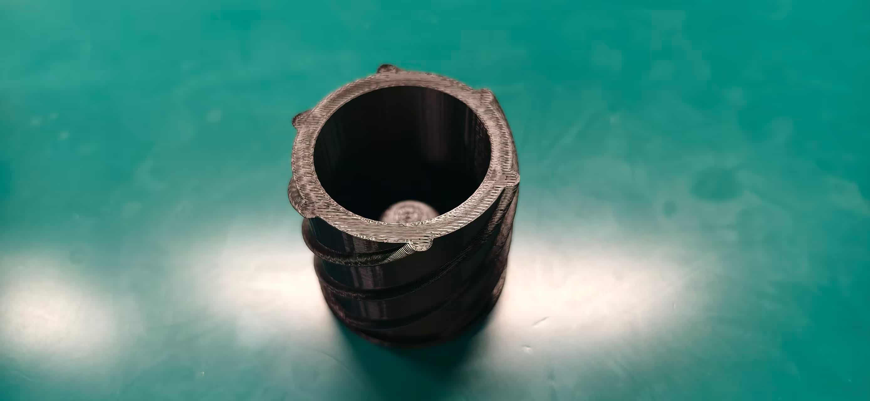
- Core feature: A trapped spherical object integrated inside the inner base.
- Design intent: Keep the outer shell closed and functional as a container, while permanently capturing a free internal volume element that cannot be assembled later.
The additive advantage (why not CNC?)
- Trapped geometry is the key: The internal sphere sits inside a closed cylindrical shell. In a standard subtractive workflow, that trapped sphere region requires internal undercuts.
- Tool access limitation: A typical 3-axis CNC endmill cannot reach behind the internal walls to carve out a detached spherical cavity/object while keeping the surrounding shell intact.
- Destructive workaround problem: To machine that sphere subtractively, you would need to split the holder open or remove wall sections for tool access, which destroys the intended one-piece geometry.
- External thread complexity: The continuous external spiral threads add complex wraparound overhang-like forms and curved transitions that are inefficient and difficult for standard subtractive toolpaths, especially on a small cylindrical part.
- Additive outcome: FDM builds the shell, threads, and trapped sphere layer by layer in one print sequence, preserving closed walls and trapped internal geometry without assembly.
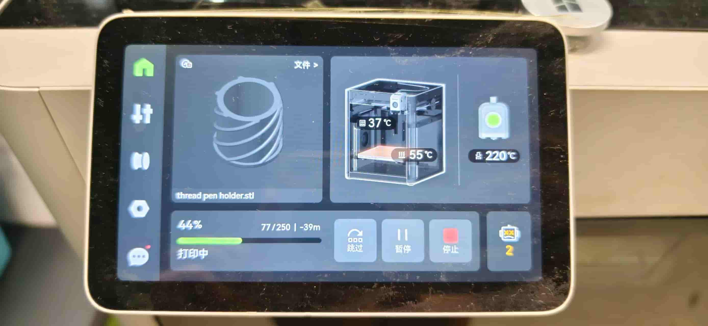
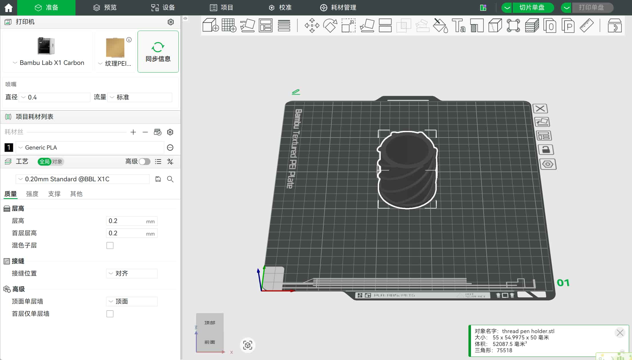
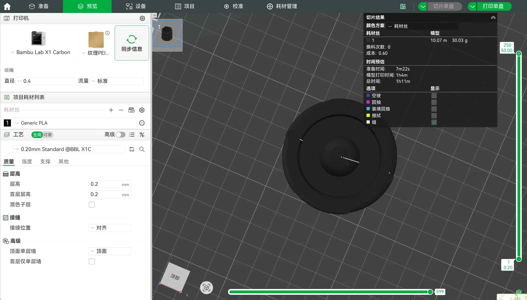
Print settings and estimated time
- Slicer estimate: just over 1 hour for the full print.
- I used this as a practical benchmark: the model is geometrically challenging, but still fast enough for iterative testing in one lab session.
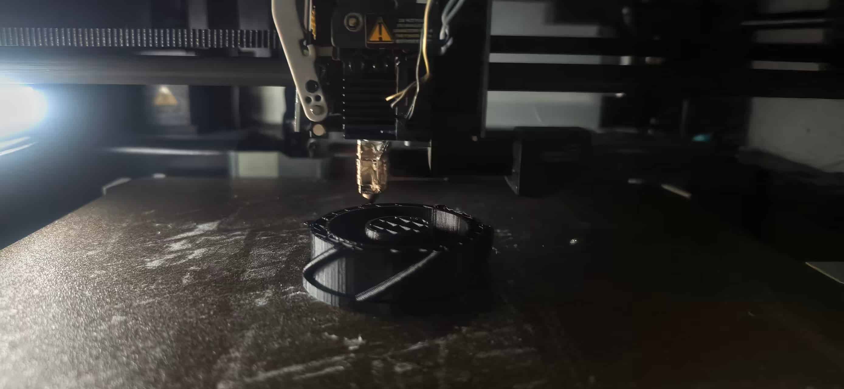
Print notes
- Build volume used: 180 x 180 x 180 mm
- Nozzle: 0.4 mm stainless steel nozzle
- Material tested this week: PLA (single-color print)
- Transfer method: Bambu Studio + Wi-Fi
- Process strategy: quick prototype first, then parametric redesign
- Printer capability note: the A1 mini can also support materials like PETG, TPU, and PVA, and supports AMS Lite for multi-color, but I did not use multi-color this week.
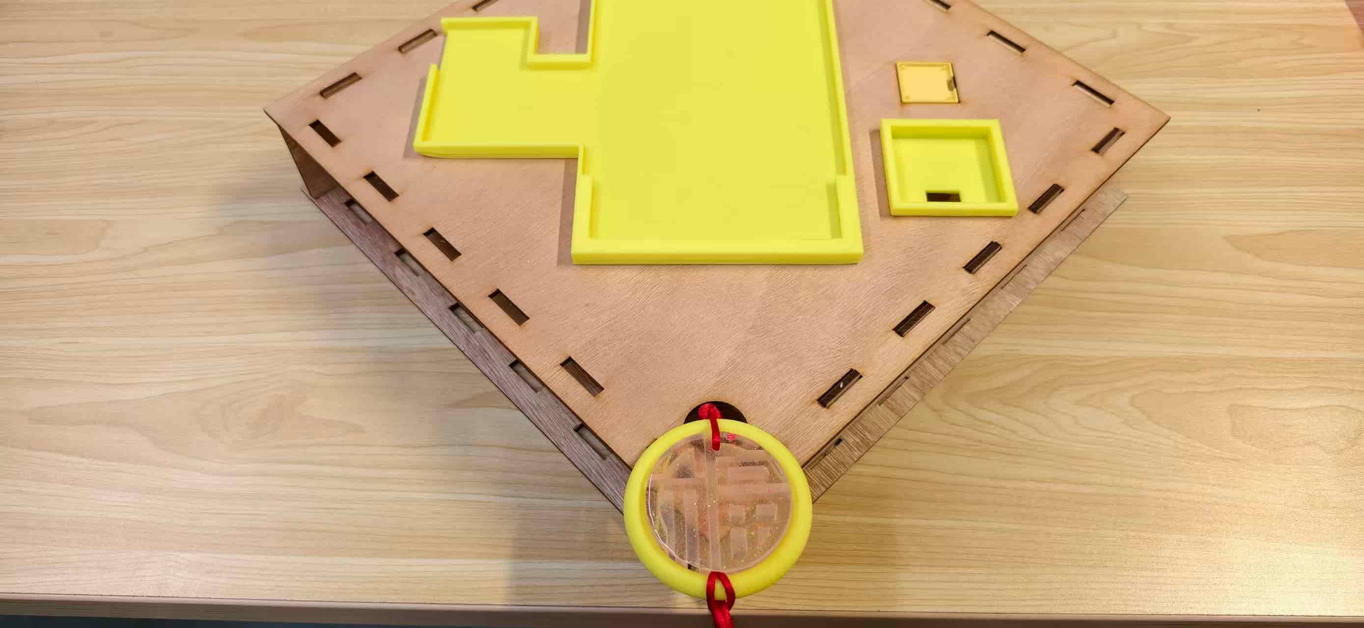
Plus. I also designed other 3D-printed inserts for my final project enclosure,including the ePaper holder and decorative cloud-pattern support,and I am quite satisfied with how they fit together:
3D scanning
I also tested two scanning tools and compared how they behaved in real use.
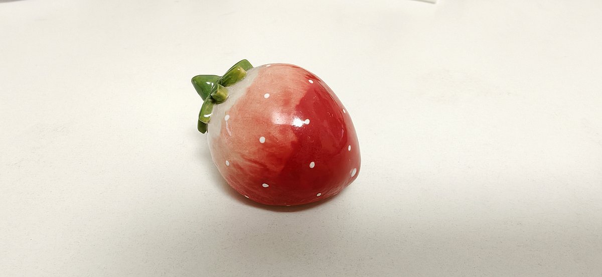
1) Polycam
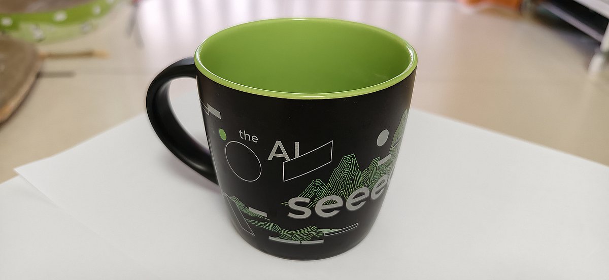
I scanned a strawberry porcelain ornament and a Seeed mug using Polycam.
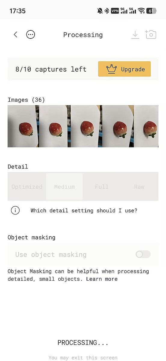
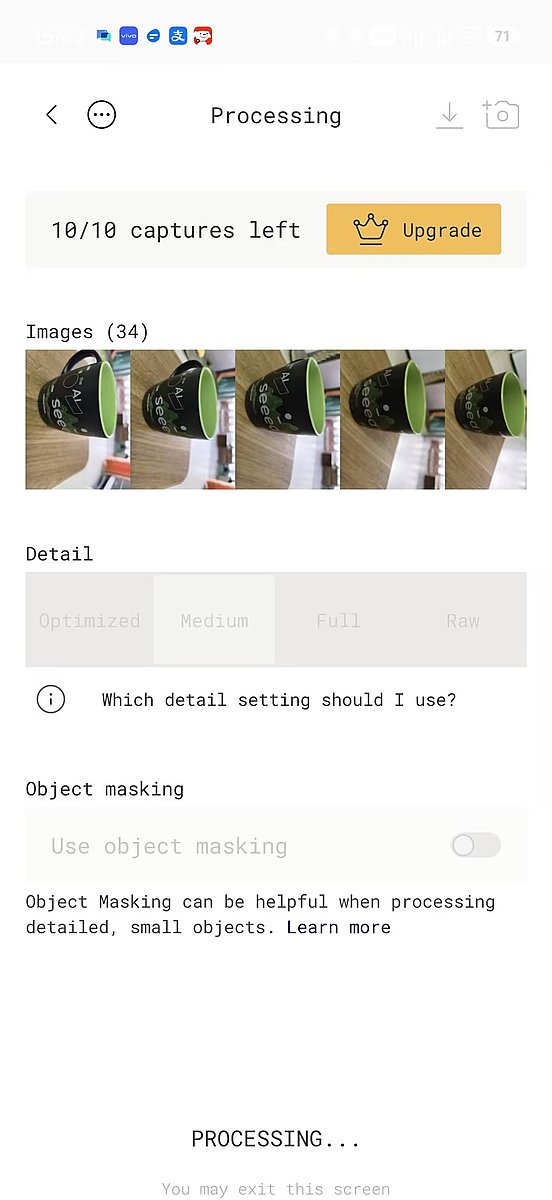
I tried Polycam several times (four attempts total).
My early scans failed when photo coverage was incomplete.
In the successful run, I took almost 60 photos around the object; around 30 photos was not enough in my test.
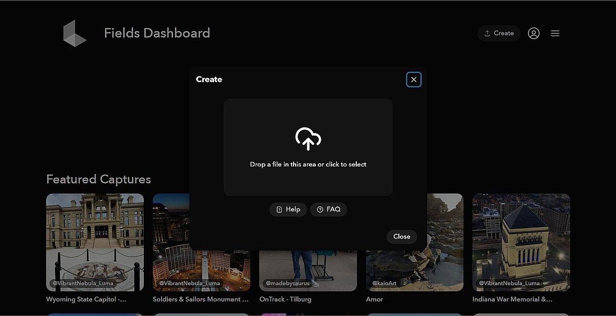
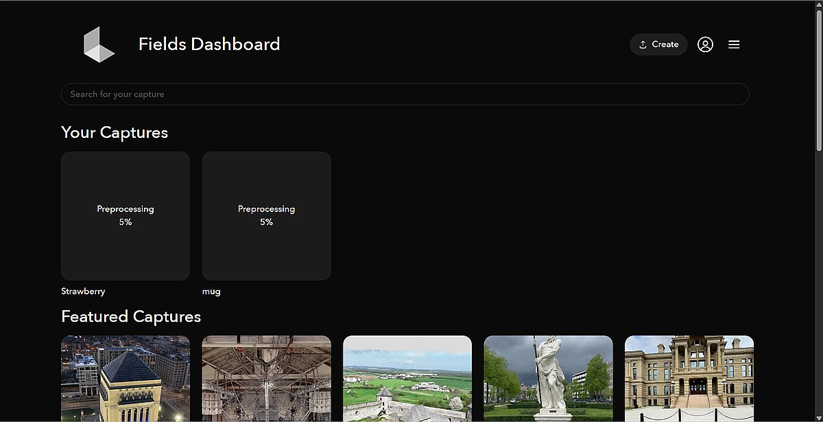
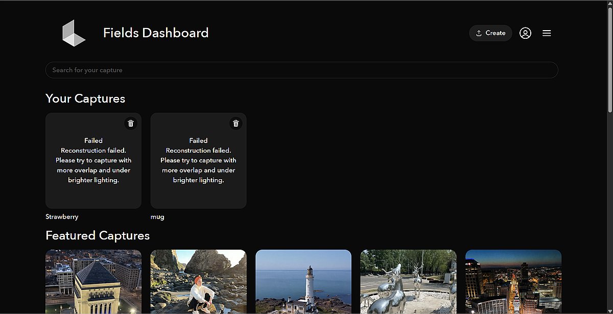
2) Luma AI
I also tried Luma AI with both photo upload and video upload.
In my case, the upload stayed at 5% for around two hours and failed.

Reflection
This week reminded me that a "nice shape" is not the same as a "printable structure." The key turning point for the Fu print was adding one continuous base layer under the Fu strokes. For the OLED holder, the turning point was thinking in assembly terms — designing the 5 mm stepped frames to match the laser-cut panel thickness so the part would snap in mechanically rather than rely on glue.
I also learned that fast tools are great for first experiments, but for real iteration I need parametric CAD. The OLED holder went through several Onshape revisions before the snap-fit and cable routing worked in the real enclosure. For scanning, coverage and patience matter much more than speed.
I like the Fu result because it keeps the traditional feeling of a window-flower Fu, but the OLED holder taught me the engineering side I needed for the final project: when geometry looks simple from one angle, it may still require additive manufacturing to combine overhangs, through-holes, and tall pillars in one piece.