Week 03: Computer-Controlled Cutting
This week's tasks were:
- Characterize the Dazu laser cutter's kerf and cutting parameters using a comb test (group).
- Design, laser cut, and assemble a parametric press-fit construction kit (individual).
- Learn the vinyl cutter workflow and complete a cut with a custom pattern (individual).
- Prototype my "Fu + screen" front panel through multiple machines and materials.
Files Reference (repository paths — use Raw on GitLab or clone the repo to download):
- First version: Fu-Panel-1.svg
- Second version: Fu-Panel-2.svg
- Third version: Fu-Box.dxf
- Vinyl cut: Fu-Character.3mf
Introduction
This week, I started working more actively in Chaihuo Makerspace. Chaihuo is Shenzhen's first makerspace, and I first heard about it nearly ten years ago during Maker Faire Shenzhen.
Today, it's still a dynamic hub with 24/7 access facial recognition at the gate, smartphone-controlled lab lights, super convenient.
What excites me most is the ideas constantly emerging here through meetups and hackathons. Now it's my turn to build something here.
Group Assignment
Full group documentation: Week 03 Group Page
Previous Machine and Settings
Since we changed a new machine on April, so I will record two machines operation tutorial here:
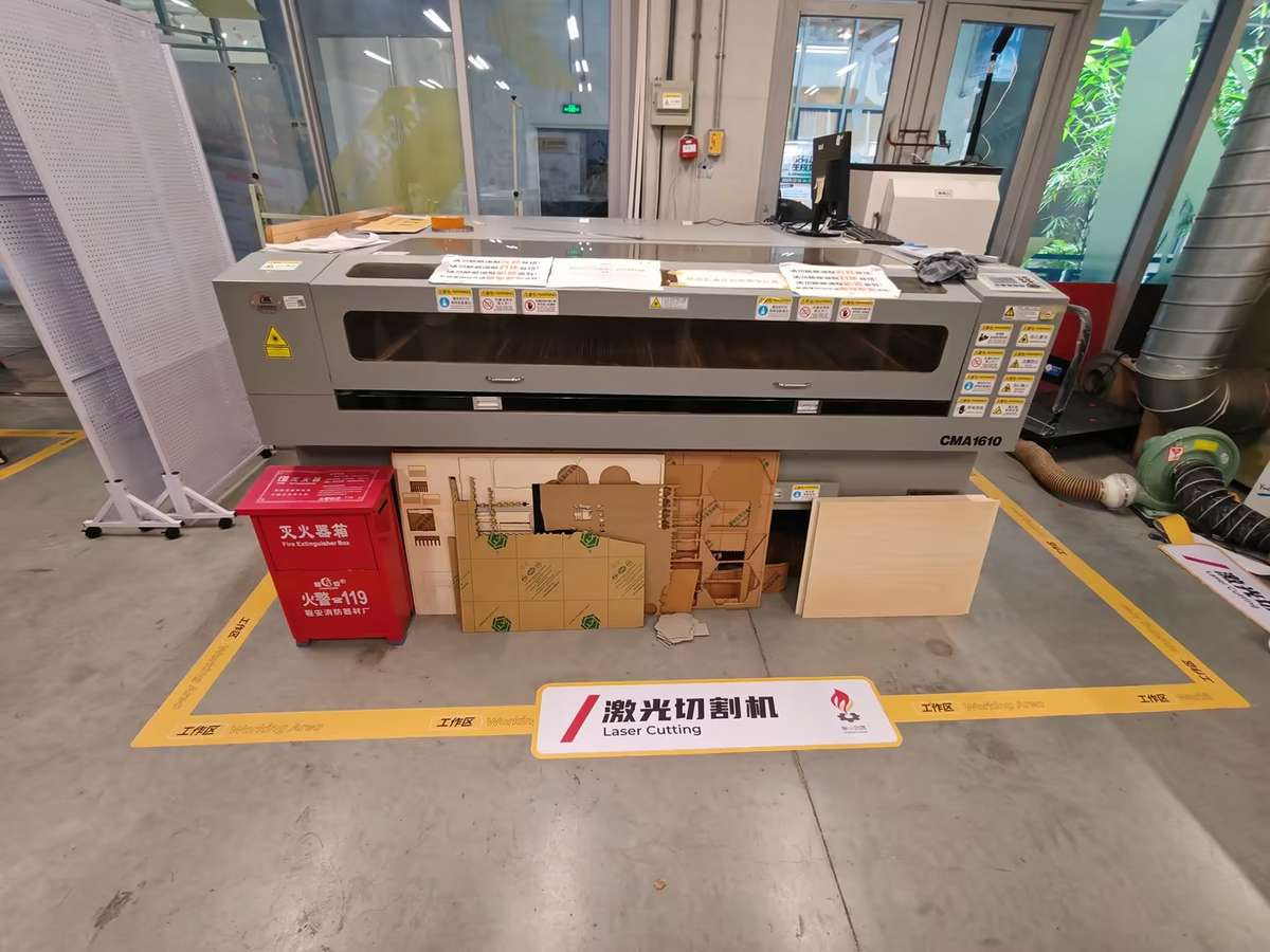
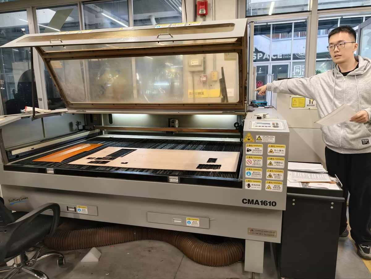
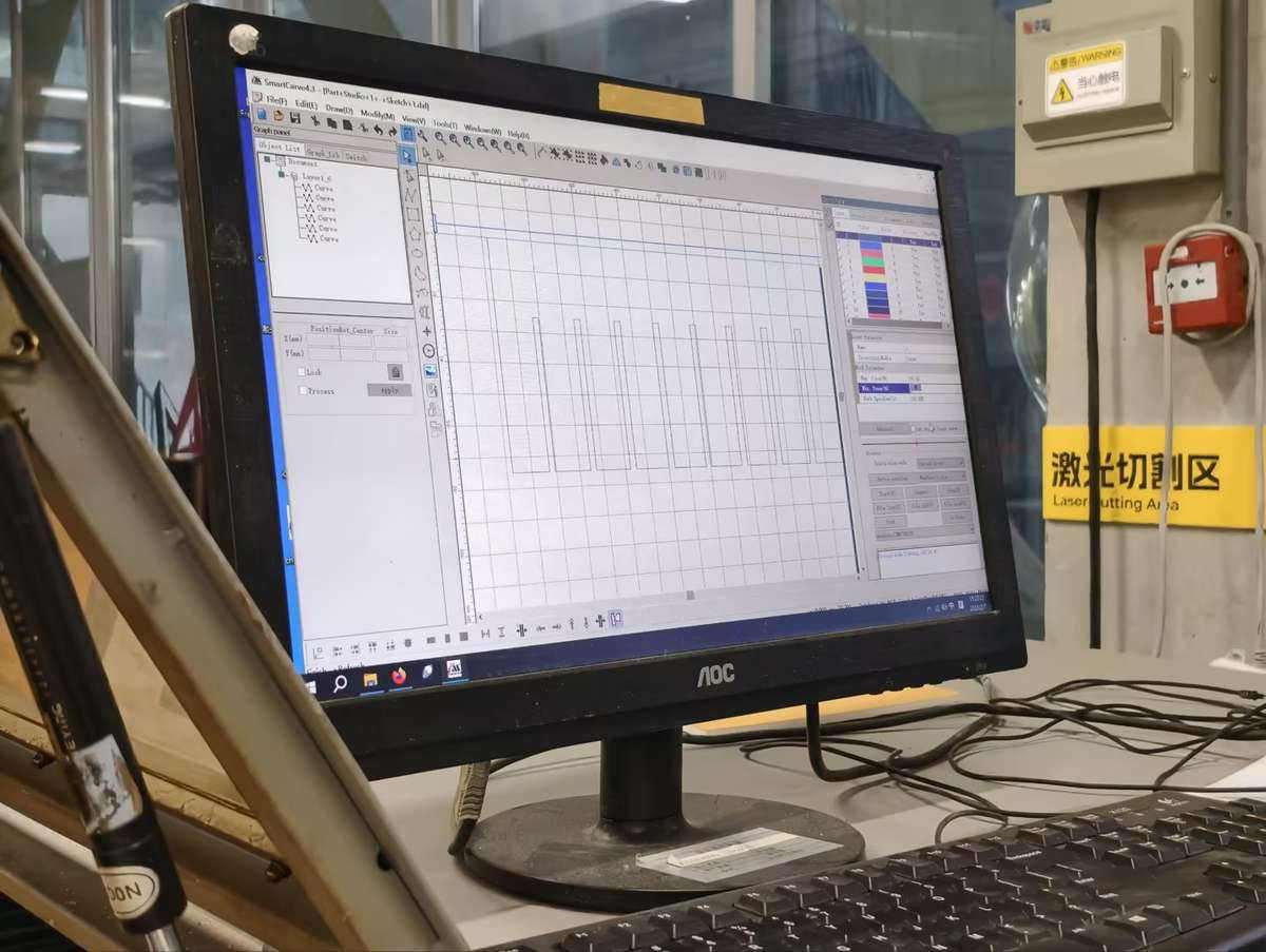
We used the Dazu laser cutter (software: SmartCarve 4.3)
Steps:
- Review safety instructions and ventilation.
- Power on machine and exhaust fan.
- Place wood flat; focus laser head using manual Z adjustment.
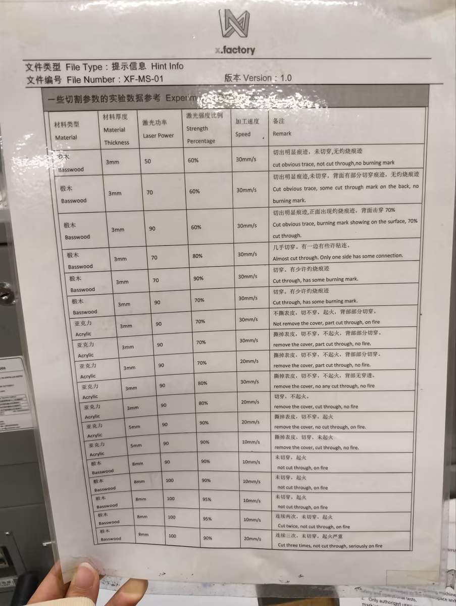
Cutting Parameters
Before designing press-fit parts, we needed to understand the kerf of the laser cutter. Kerf is the small amount of material removed by the laser beam during cutting. Even though it is small, it directly affects how tightly two parts fit together.
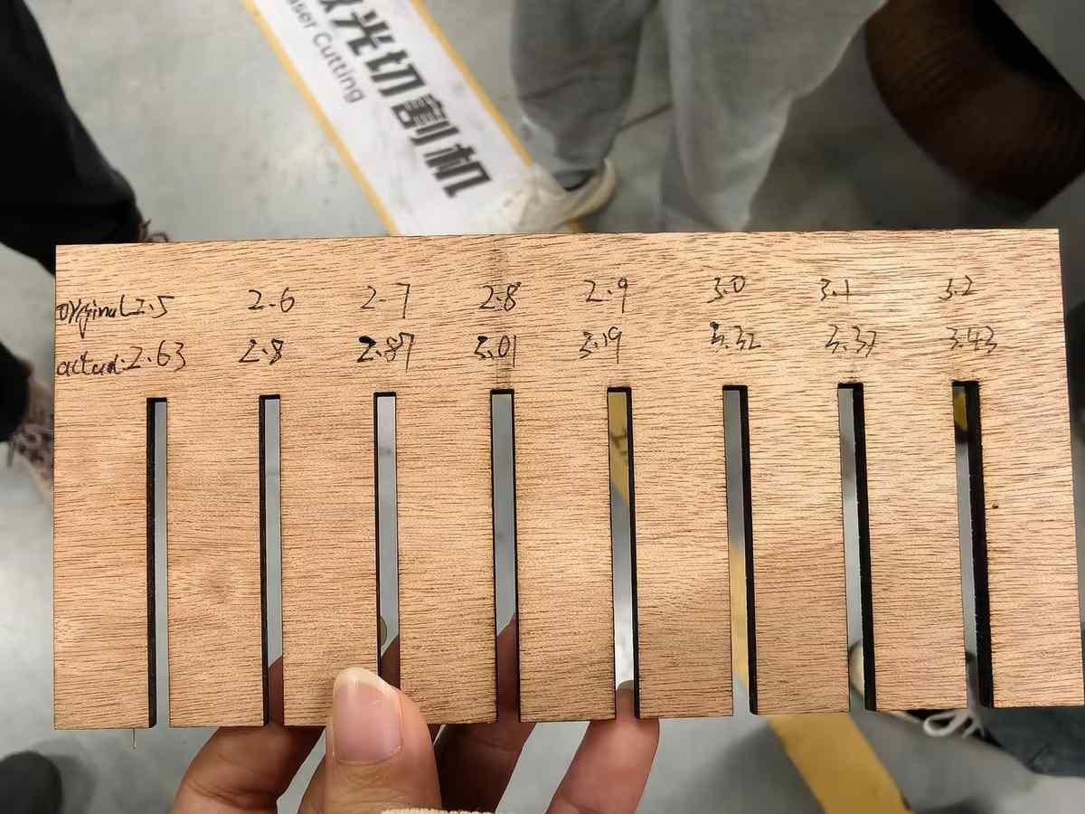
Comb design: DXF file with slots from 2.4–3.2mm (0.1mm steps) to measure kerf.
Settings (black lines, single layer):
- Max power:
80% - Min power:
50% - Speed:
30 mm/s
Framing test confirmed material coverage. Cut took ~2 minutes—comb ejected cleanly, no burns.
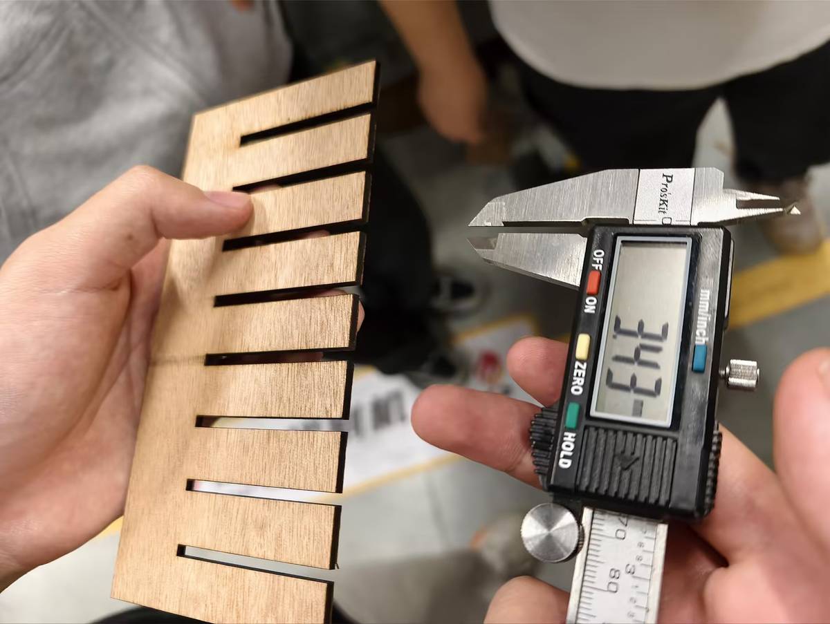
Kerf Measurement
We cut combs and tested fits:
- Material thickness: 3mm (caliper average from 10 strips).
- Snug fit at 2.75mm slot (actual width post-kerf: ~6.0mm).
- Kerf: 0.15mm (slot + 2×kerf radius ≈ thickness). Range across tests: 0.12–0.20mm.
This matches typical CO2 lasers on wood; slower speeds reduce variability. I carried the 0.15mm kerf value forward into my individual connector design.
Vinyl Cutter Introduction
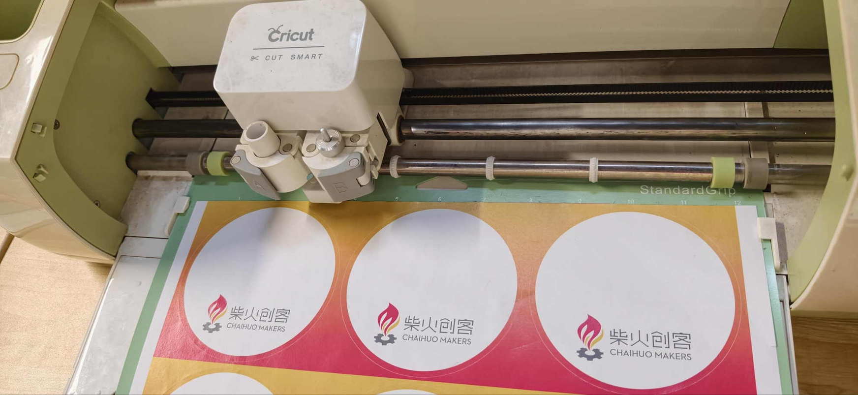
Quick test on Cricut machine via Cricut Design Space:
- Imported a simple vector (logo sticker).
- Vinyl sheet loaded, pressure roller set to medium.
- Cut in 10 seconds; weeded cleanly.
Basic but precise for decals. I later ran a longer individual test with Fu patterns; see Vinyl cutting (Cricut) below.
Individual Work
I produced three outputs this week across four cutting sessions. The table below gives a quick orientation before the full details.
| Session | Machine | Material | Outcome |
|---|---|---|---|
| 1 | Dazu / SmartCarve 4.3 | 3mm wood | Frame did not cut through |
| 2 | Seeed xTool | 2mm acrylic | Clean cut; panel cracked during film removal |
| 3 | SMDX (new Chaihuo machine) | 3mm wood | Parametric connector — clean press-fit |
| 4 | SMDX (new Chaihuo machine) | 3mm wood | First 3D box — 2 of 4 sides aligned |
Design Goal
For my individual assignment, I wanted to prototype the front panel of a future electronics box for my final project.
The main visual idea comes from the traditional Chinese Fu (福) character decoration. In daily life, Fu is often displayed in a square or diamond shape, usually between 300mm and 600mm wide.
I decided to start with the smallest practical version and turn it into a functional front panel, combining cultural decoration with an electronics interface:
- the outer shape references the traditional Fu decoration
- the inner rectangular opening holds a screen
- the screen could display the Fu character, weather, date, or other information
- a small circular hole is reserved for a button or switch
- a top hole could be used later for hanging or mounting
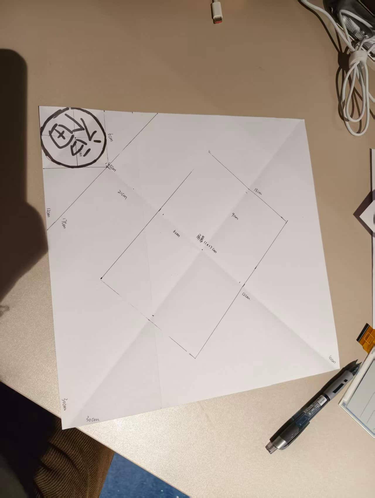
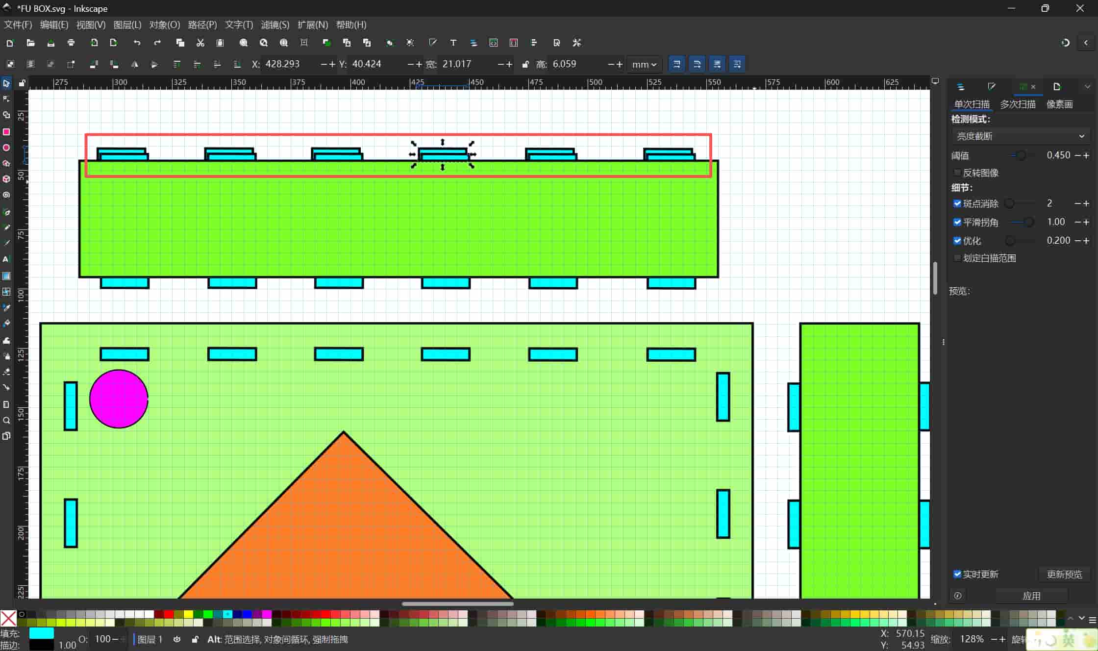
First Design Attempt
I started by sketching the layout on paper, then used Inkscape to check and simulate the dimensions. My first digital design was about 300 × 300 mm. I placed two decorative Fu elements beside the inner screen window and added a circular hole above the rectangle. Because the Fu motif reads as a diamond when cut, the real footprint on the material grew larger than a simple square sketch, so I looked for scrap wood panels larger than 30 × 30 cm to stay safe. At this stage, I was mainly testing whether the layout could be cut cleanly and whether the different functional areas were positioned reasonably.
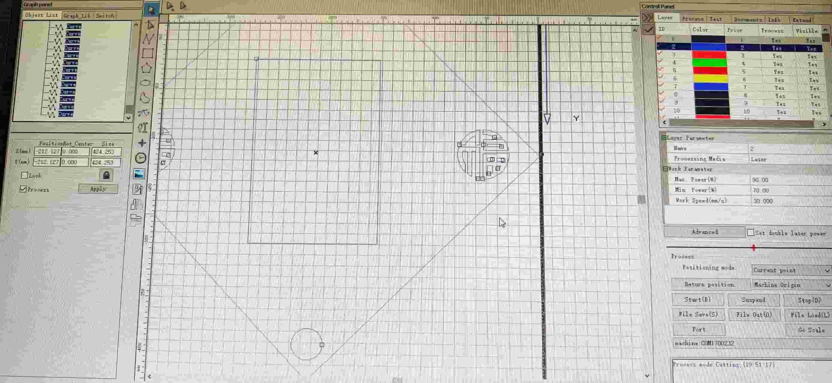
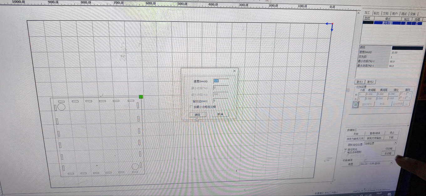
First Cutting Test: Chaihuo Dazu Laser
I first tested the design at Chaihuo Makerspace using the Dazu laser cutter and SmartCarve 4.3. I moved the file from my phone to the lab computer over WeChat, then opened SmartCarve and calibrated the job. My goal was to cut two vertical holes and one central rectangular opening for the screen, and to engrave two Fu (福) motifs on the sides.
Material
- 3mm waste wood
File
- DXF imported into SmartCarve 4.3
Layer settings
- Fu characters for engraving: Max Power
50%, Min Power30%, Speed30 mm/s - Outer frame, circles, and rectangles for cutting: Max Power
90%, Min Power70%, Speed30 mm/s
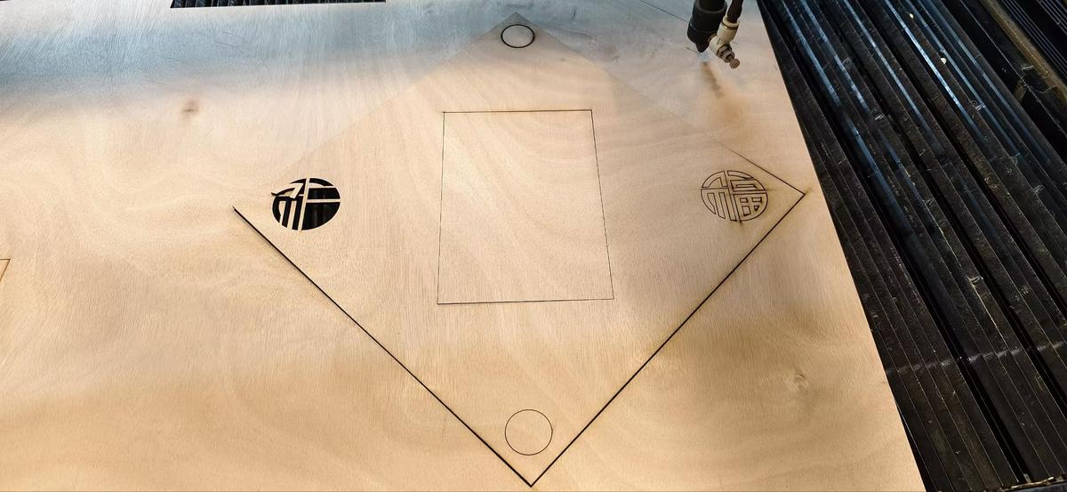
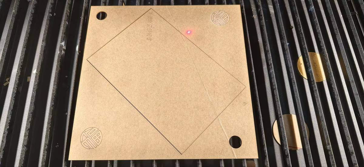
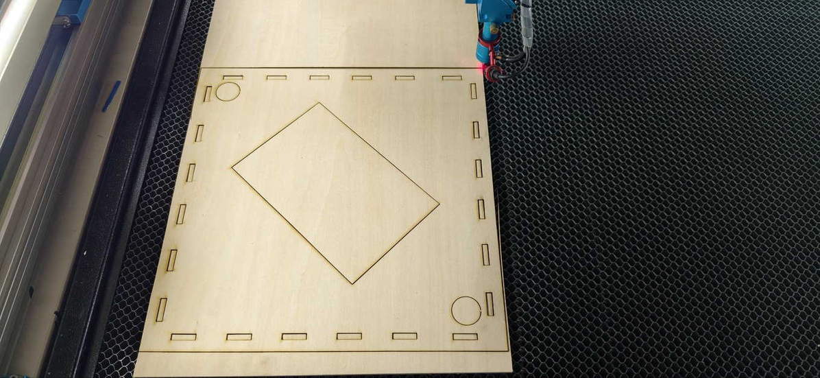
Result of the First Test
The result was only partly successful:
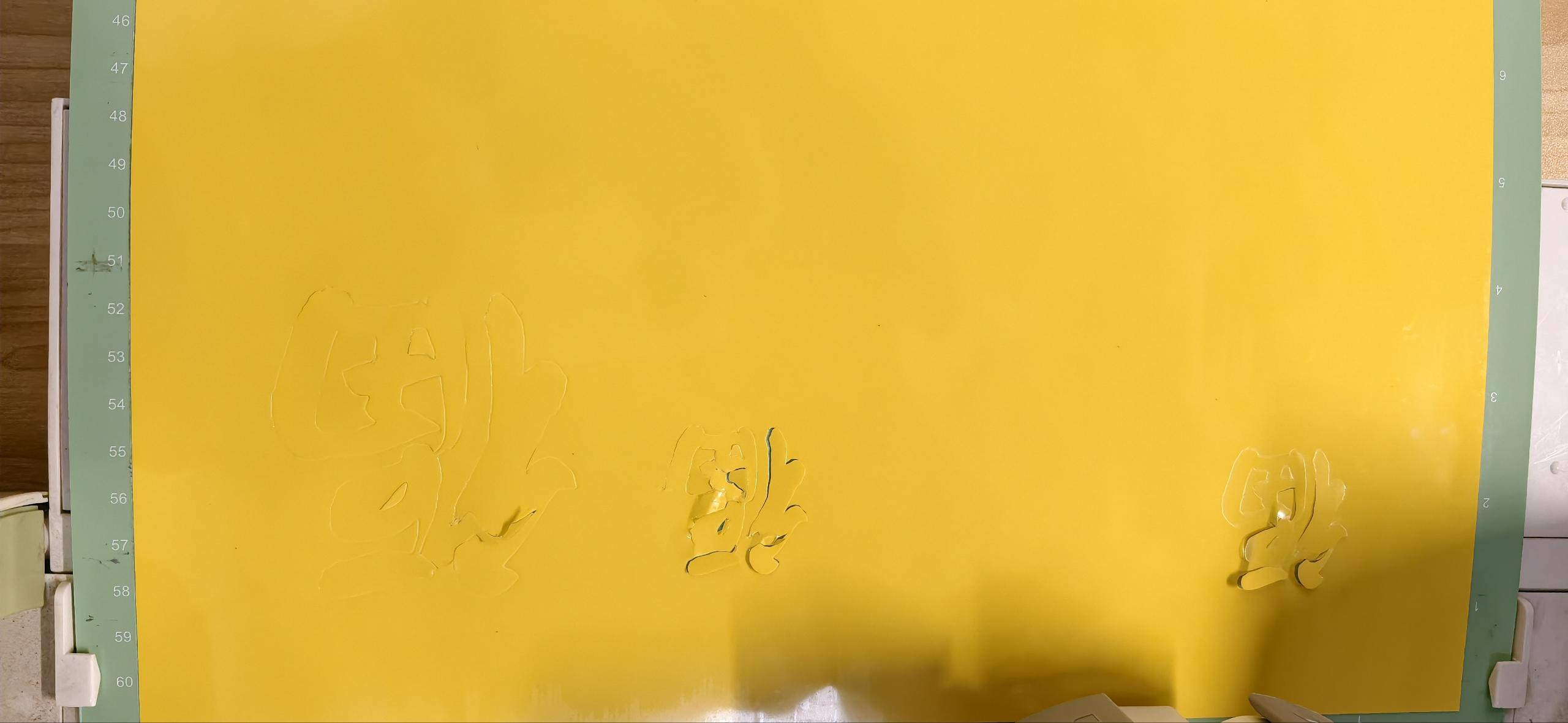
- the engraved Fu characters came out clearly
- the button holes were cut cleanly
- the outer frame did not cut through completely
- only two sides were fully cut; the other two were left as shallow score lines
This meant the decorative and small internal features worked better than the large outer cut.
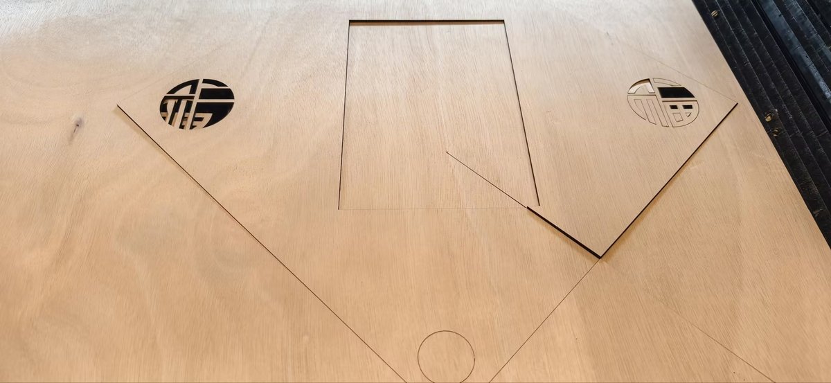
What Might Have Gone Wrong
After this failed cut, I discussed it with Emily and tried adjusting the settings again.
Debugging ideas
- Emily suggested increasing the settings to
95% / 75% - I repeated the cut, but the result was still inconsistent
On another attempt, roughly half of the square frame still did not cut through cleanly, while the engraved Fu seal looked excellent. My instructor suggested the inconsistency might come from the machine itself or from slight unevenness in the wood surface.
At that point, I thought the problem might be caused by one or more of these factors:
- the wood was too thick for a reliable single-pass cut
- the board surface was not perfectly flat
- the laser focus may not have been fully consistent across the whole area
- the larger frame cut may have been more sensitive than the smaller holes and engraving
Unfortunately, the laser was broken, and our manager decided to purchase a new one.
Second Test: Seeed xTool Laser
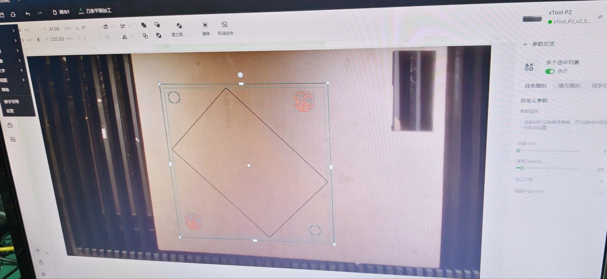
While waiting for the new Chaihuo machine, I tried again on a Seeed Studio xTool laser. I redrew the layout in xTool Creative Space—the interface felt clearer and easier to use than SmartCarve for this workflow. I also switched materials and scale:
- scaled the design down to
220 × 220 mm(the bed is smaller than the Dazu) - moved the inner rectangle slightly away from the outer edges
- narrowed spacing to about
5 mmbetween the screen window and the outer frame - added about
10 mmmore margin where possible to improve cutting reliability - changed the material from 6mm wood to 2mm acrylic
Material
- 2mm acrylic
Settings
- Max Power
60% - Min Power
40% - Speed
25 mm/s
Result of the Second Test
This time, the cut was successful:
- the edges were smooth
- the cut went through completely
- the full panel finished in about 20 seconds
- the final shape looked much cleaner and more precise
The main limitation was the smaller machine bed, which meant I had to reduce the panel size. One practical issue only showed up after the cut: the gap between the screen opening and the outer frame was tight enough that the acrylic cracked slightly at the corners when I peeled off the protective film—another reminder that "looks good on screen" still has to survive handling.
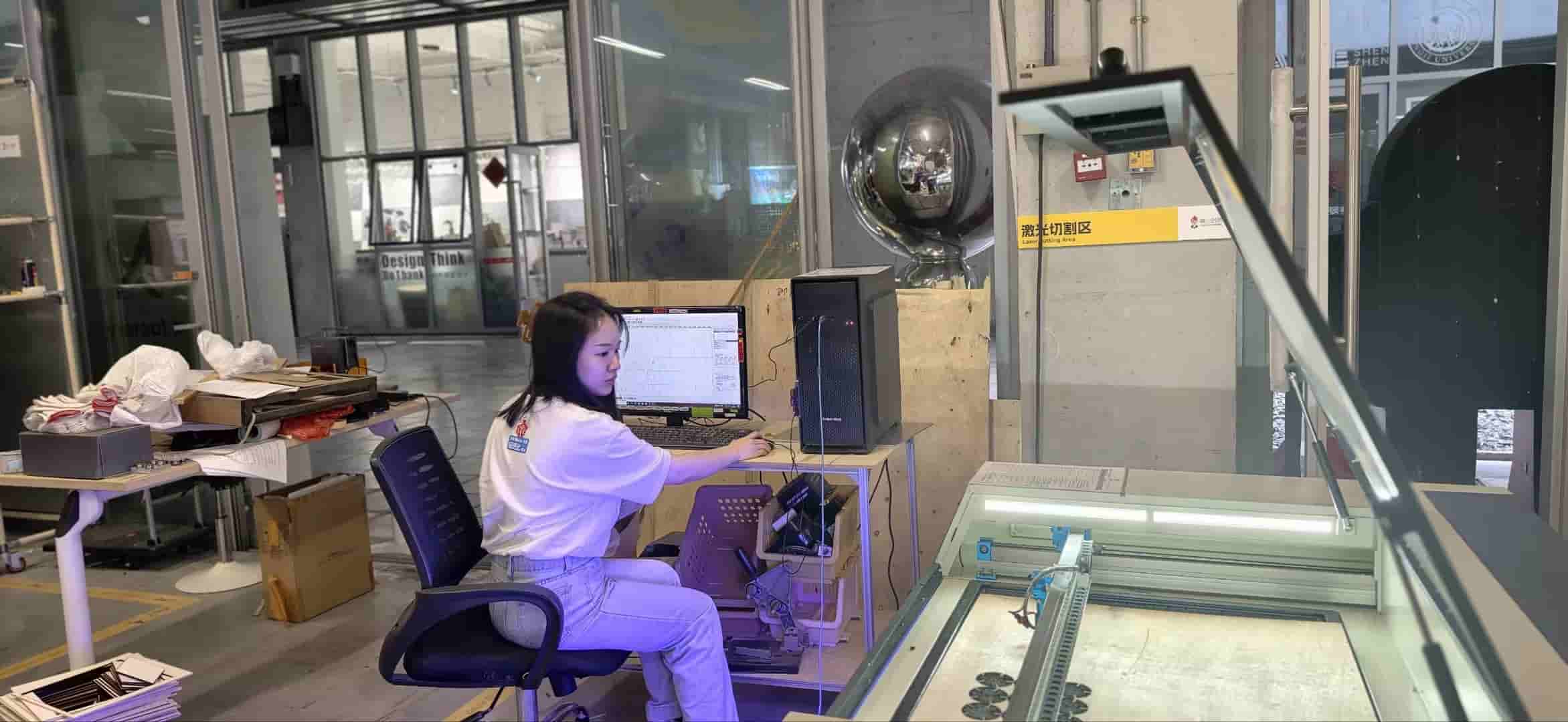
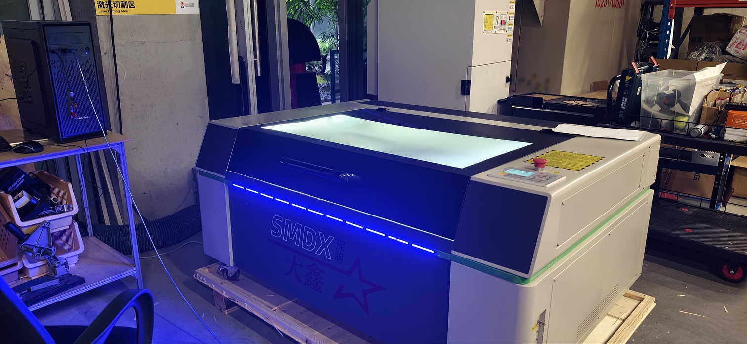
Third Test: New SMDX Machine
Parametric Press-Fit Connector
For the parametric press-fit kit, I designed a circular connector with a 50mm diameter to serve as the base joint. The key requirement for Fab Academy is that the design is parametric: changing the material thickness should automatically update the slot width, not require manual redrawing.
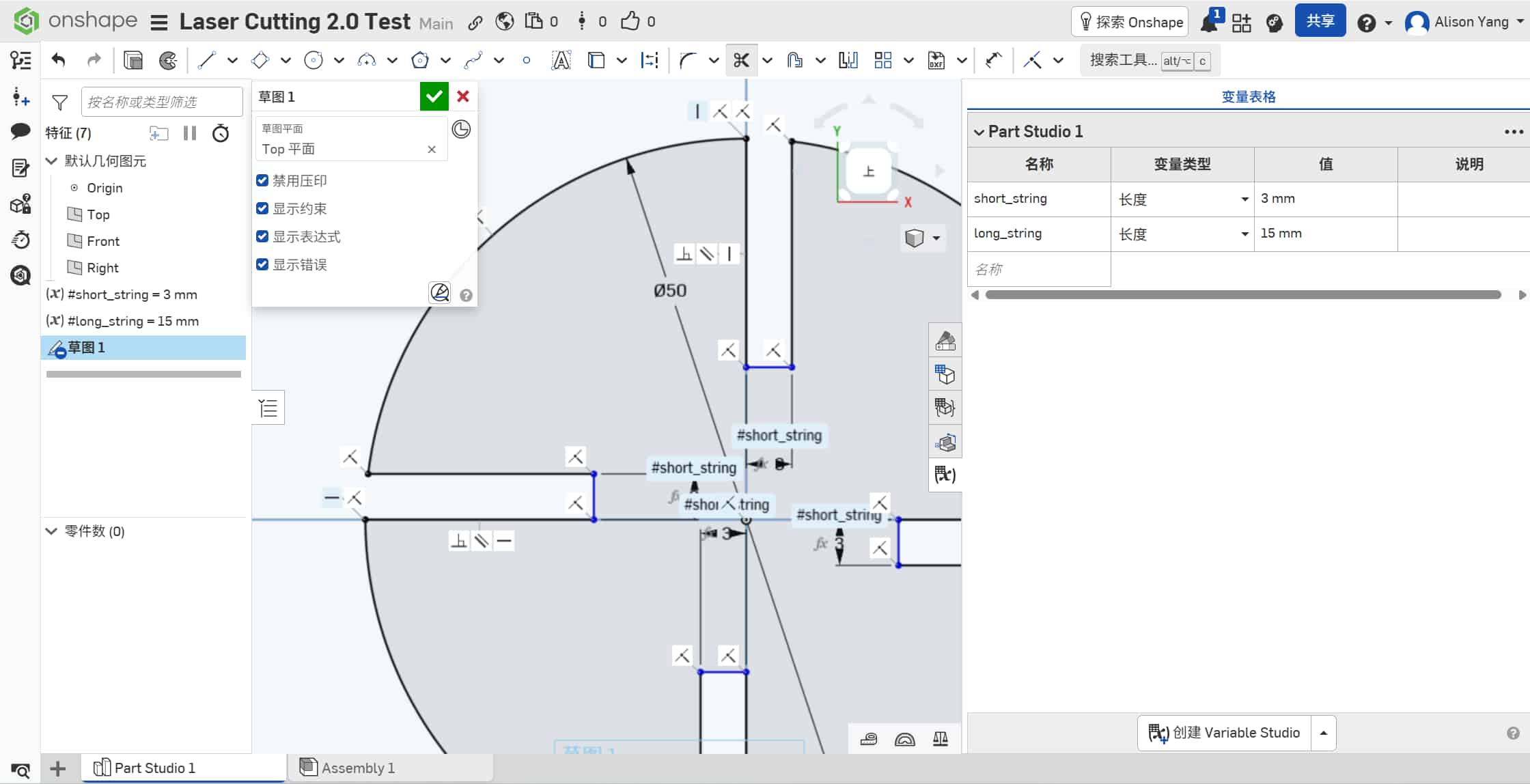
In Onshape, I set up two driven dimensions at the sketch level:
thickness = 3 mm(material thickness)slot_width = thickness − kerf = 3 − 0.15 = 2.85 mm
By drawing the slot at 2.85mm, the laser widens it by the measured kerf (0.15mm) to reach the actual 3.0mm needed for a snug fit. Changing thickness in the parameter list updates slot_width across all four slots automatically.
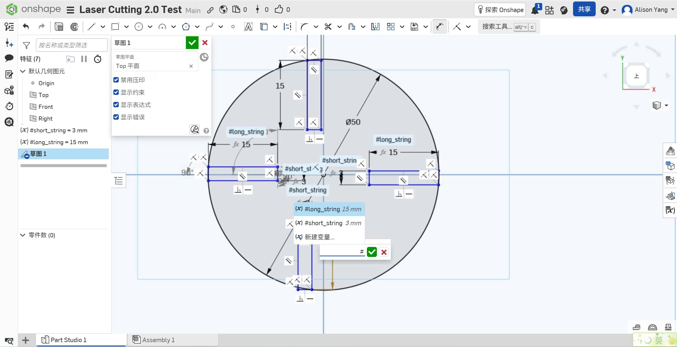
Workflow:
- I drew a main circle (
50mmdiameter) and positioned a rectangle (15mm × 2.85mm) on the left quadrant of the perimeter. - Using Onshape's sketch constraints, I fully defined the slot dimensions as driven values.
- I used the Trim tool (scissors icon) to remove the overlapping arc segments between the circle and the rectangle, creating a clean opening.
- I duplicated the slot using the Circular Pattern tool, rotating it 90° three times to produce four identical, symmetrically spaced interlocking slots.
Laser Cutting the Connector
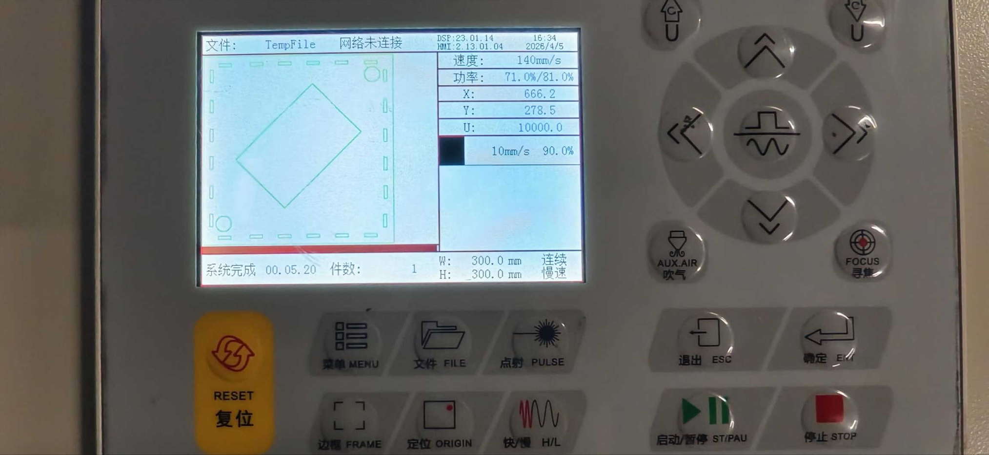
I cut the connector on the SMDX machine at Chaihuo.
Material
- 3mm cardboard
Settings
- Max Power:
90% - Min Power:
50% - Speed:
10 mm/s
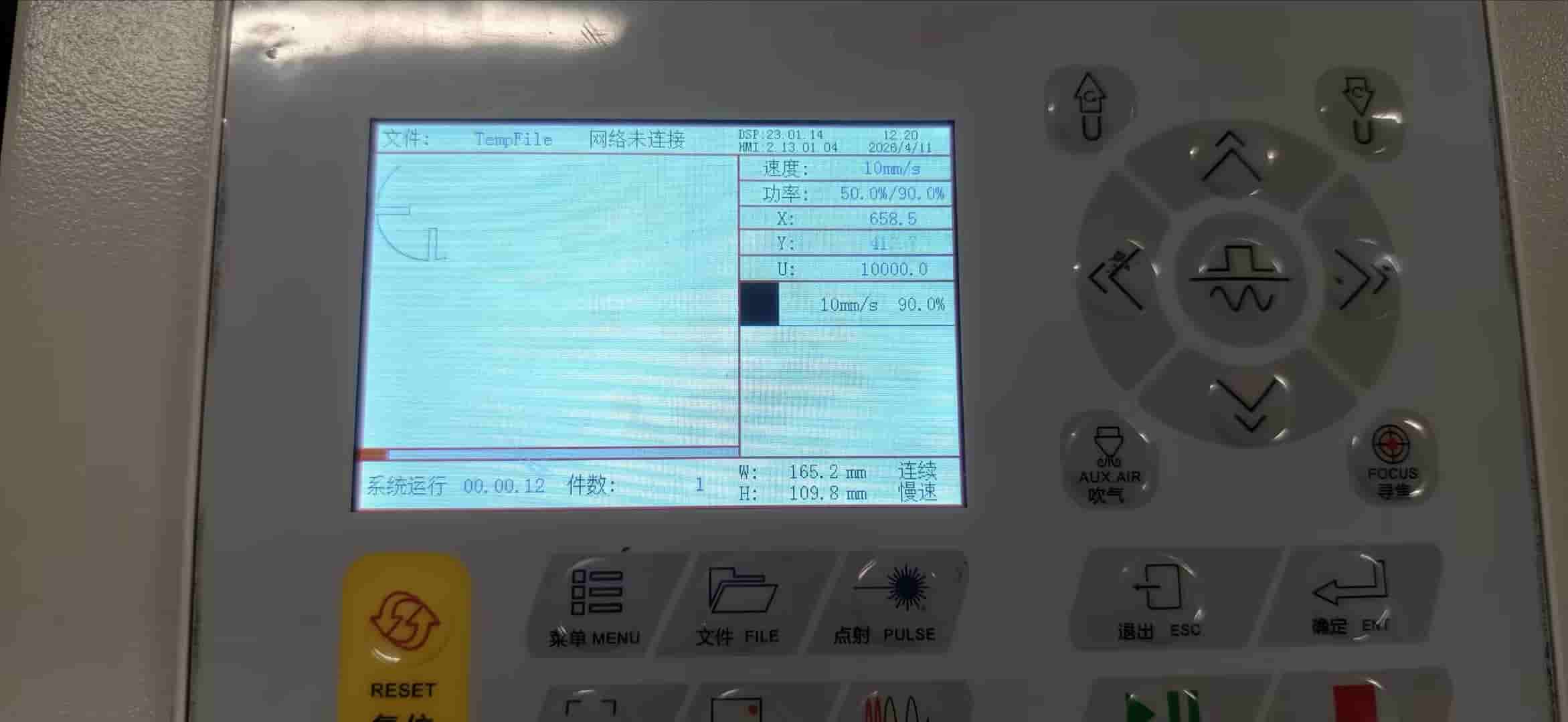
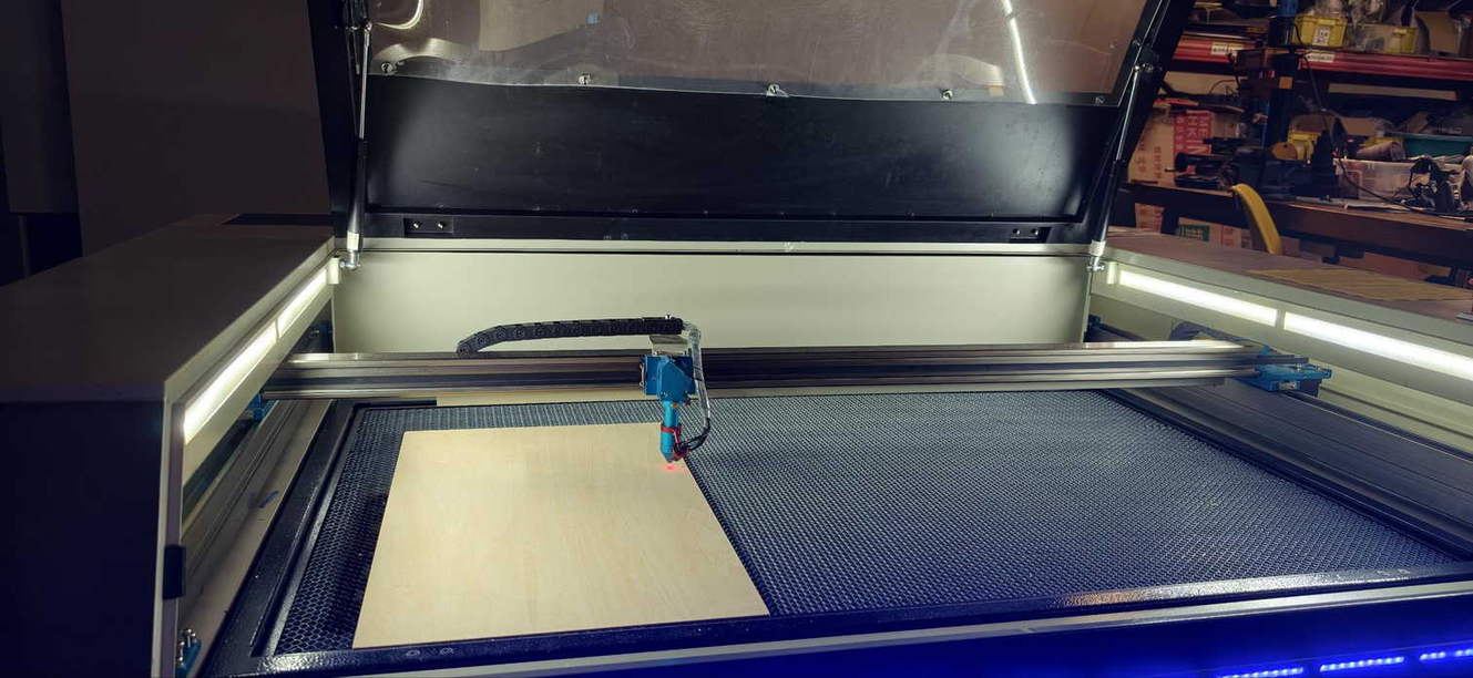
Preparation:
I exported the sketch from Onshape as a DXF file and transferred it to the laser cutter via USB drive. After importing the file into the SMDX software, I calibrated the Origin (X-Y zero point) and ran a Frame test (walking the boundary) to confirm the design fit within the material dimensions.
Execution:
Once the alignment was confirmed, I closed the safety cover and initiated the cut. The connector finished in under 30 seconds.
Results and Assembly
After the cutting was complete, I waited for the ventilation system to clear the smoke before retrieving the pieces.
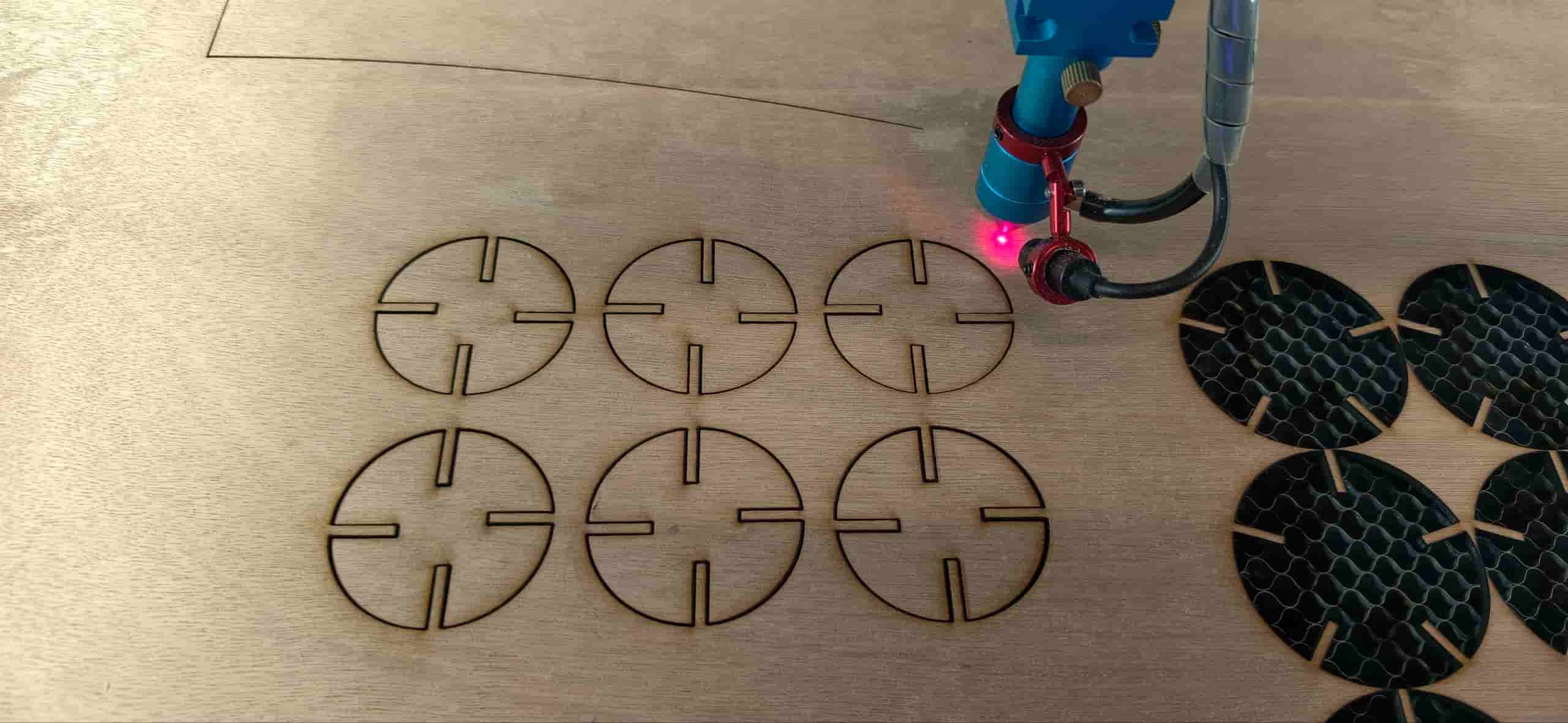
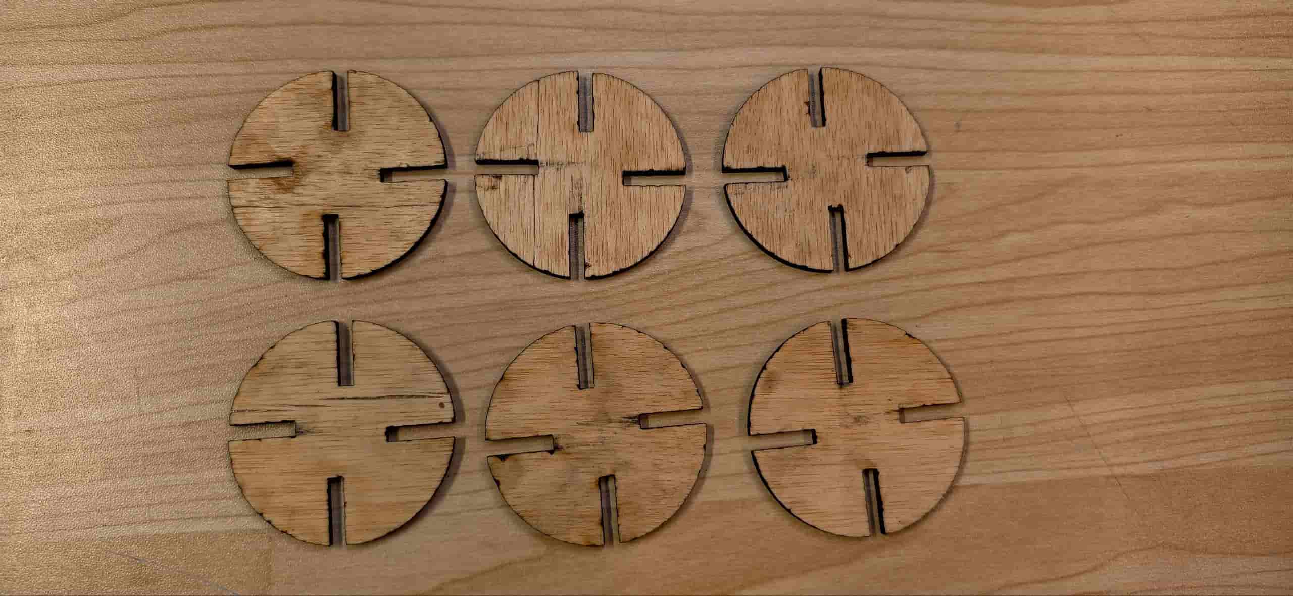
Observations: Due to a slightly high power setting, there was some minor charring (black soot) along the edges. It didn't affect structural integrity, but reducing power by about 5% would likely keep the edges cleaner next time.
Fitment: The parts fit together perfectly. The friction between the slots was just right—tight enough to hold the structure without glue, yet easy enough to disassemble.
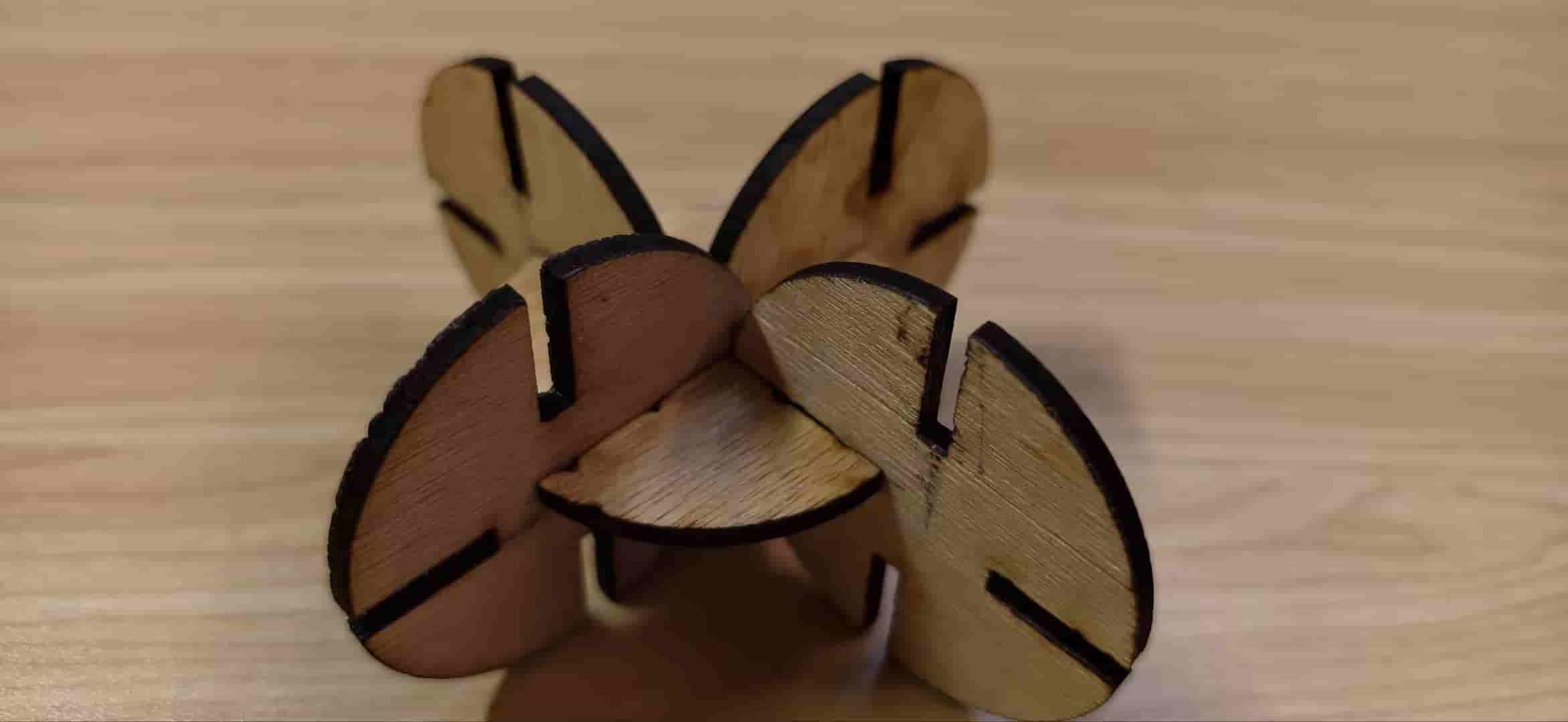
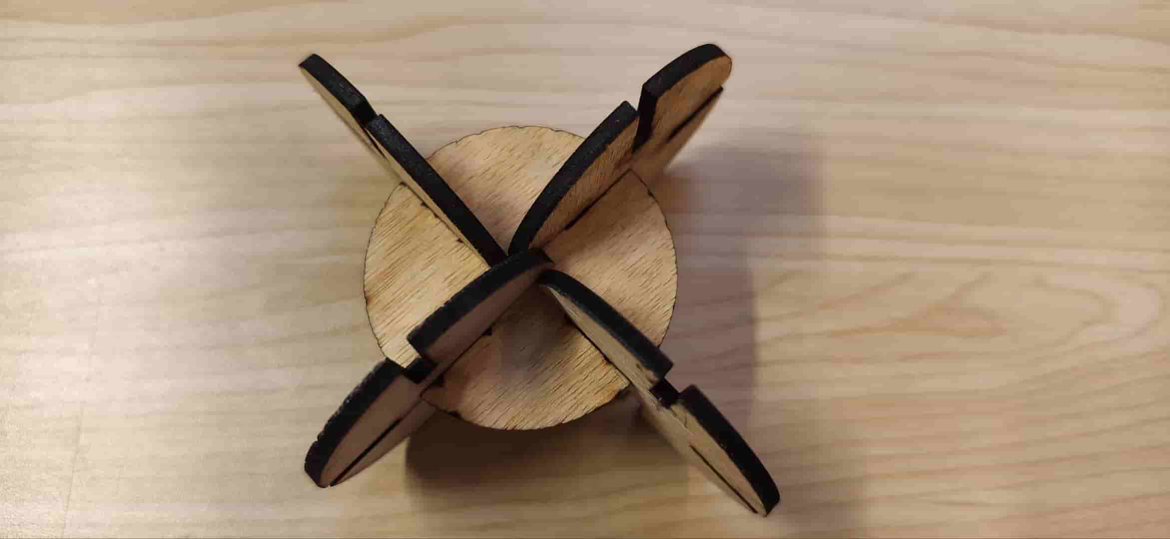
The kerf calculation worked as expected: the 2.85mm drawn slot became a ~3.0mm real opening after cutting, matching the 3mm material thickness for a snug press-fit.
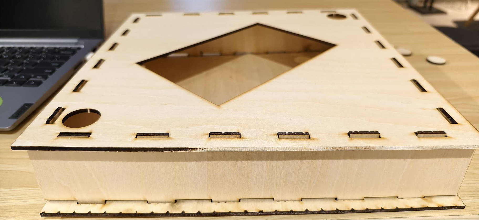
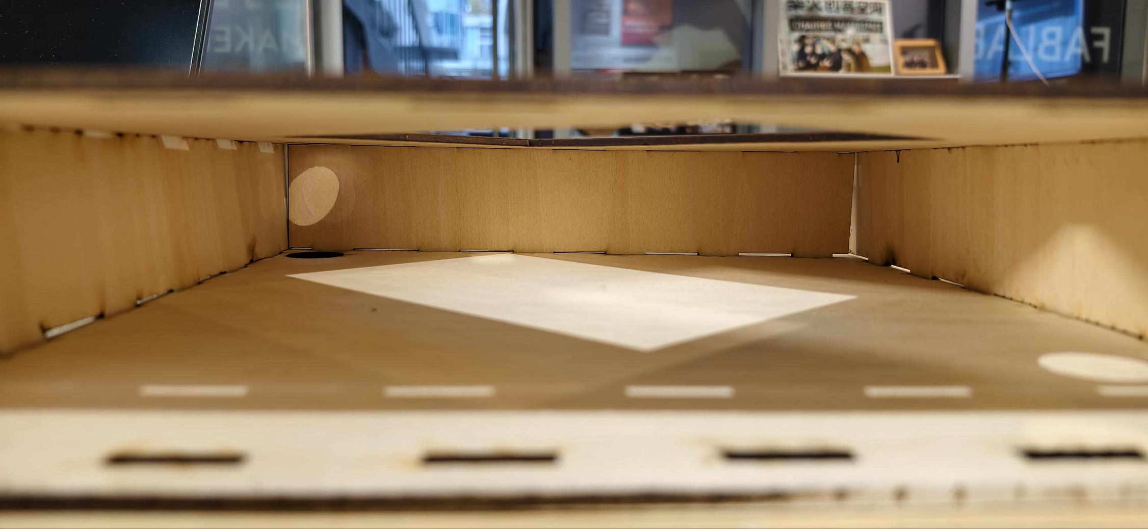
First Box Cut for Final Project
After get more familiar about SMDX laser at Chaihuo, I went back to testing the full box idea, not only a flat panel. On April 6 I ran a third round on the new machine.
Setup was easier than before, and the bed can handle materials up to about 60 × 100 cm. My stock was 30 × 30 cm; I laid the paper sketch beside the machine and arranged the parts flat on the sheet to save space.
Target box (this iteration)
- Outer size:
30 × 30 cm - Inner box opening:
12 × 18 cm - Holes:
2 × 0.5 cm(as drawn in the file)
I exported a DXF, copied it to the PC by USB, and opened it in the cutter software. The wood panel was only 30 × 60 cm, so I split the geometry into three separate cuts instead of one large job.
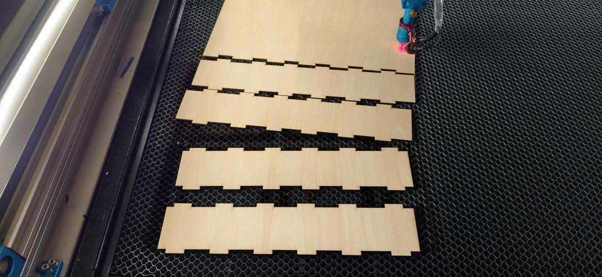
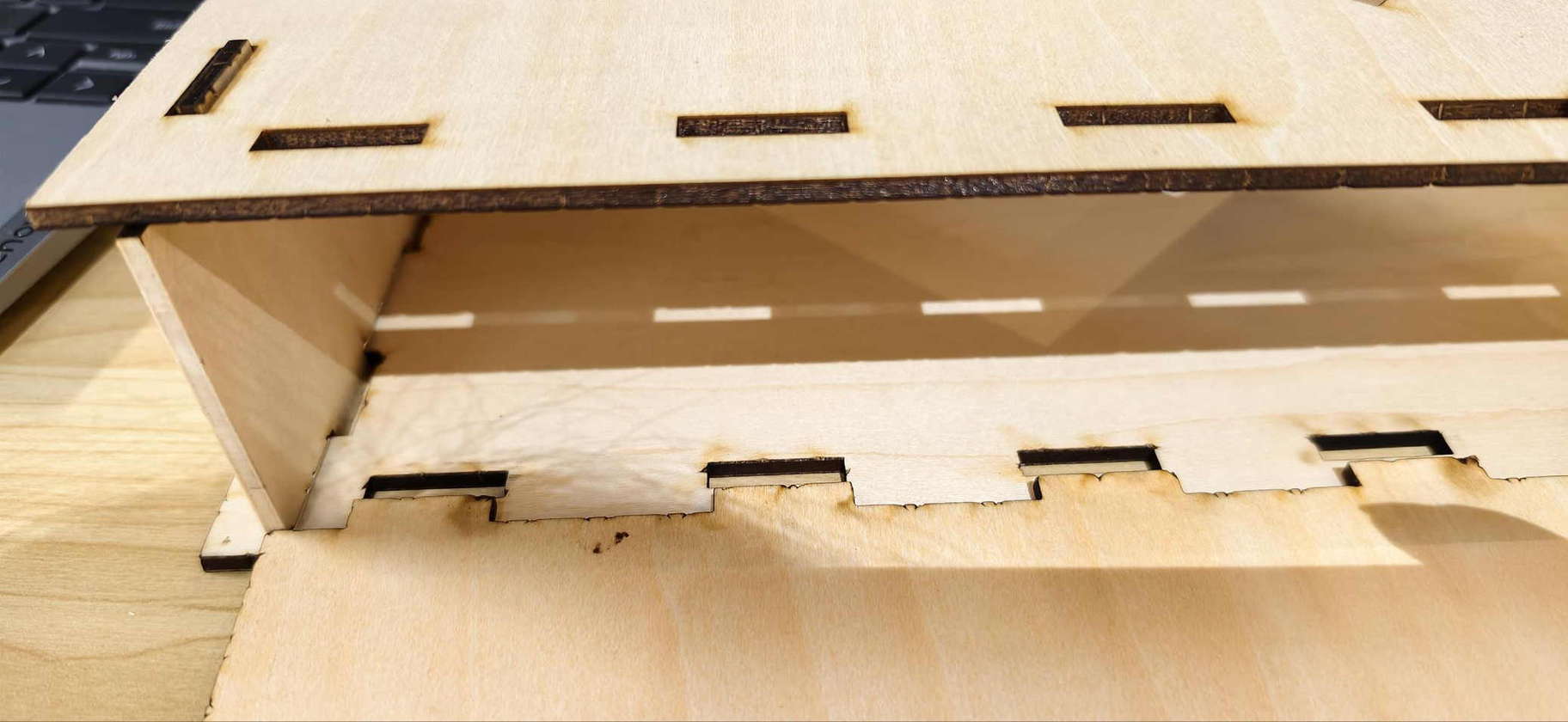
After cutting, I tried assembling the box. Only two sides met perfectly, but the overall 3D shape already looked promising—a satisfying first try at a real structure rather than a single face.
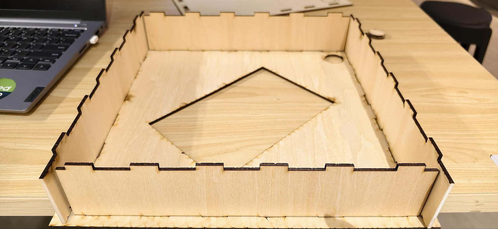
The misalignment traced back to the design phase: during earlier tests, some hole positions had been slightly off; those small errors carried through and amplified when the parts had to meet in 3D.
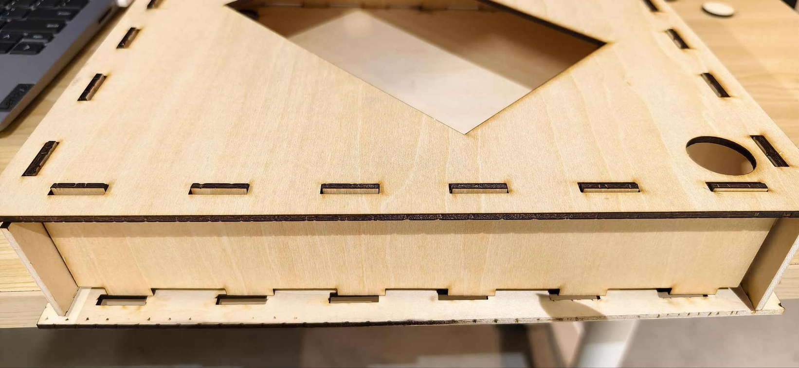
Except for the misalignment, everything looks pretty well.
My instructor suggested that Inkscape might not be ideal for mechanical precision at this level, and recommended Onshape; I rebuilt the box and then designed the press-fit connector there for the next iteration.
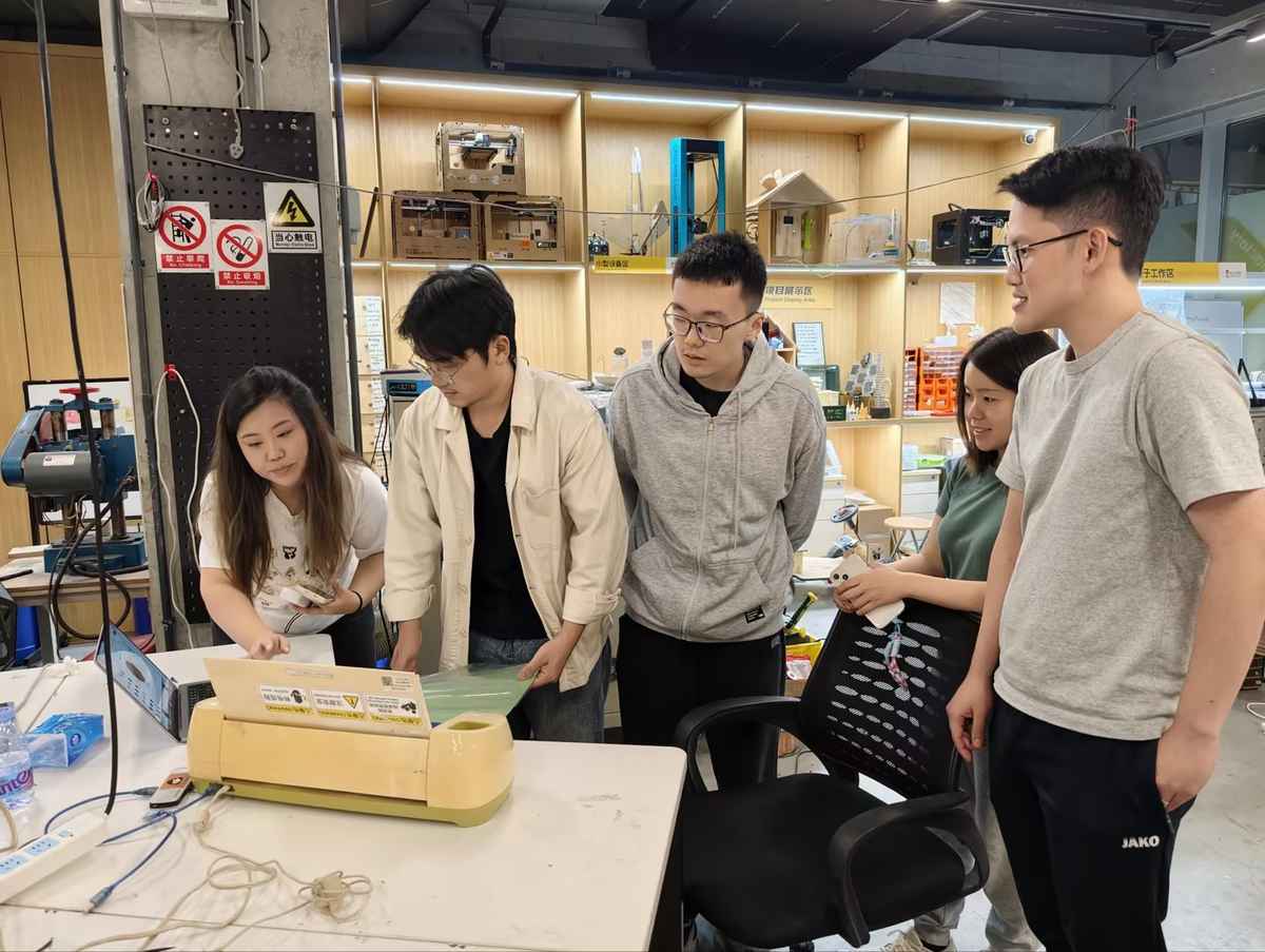
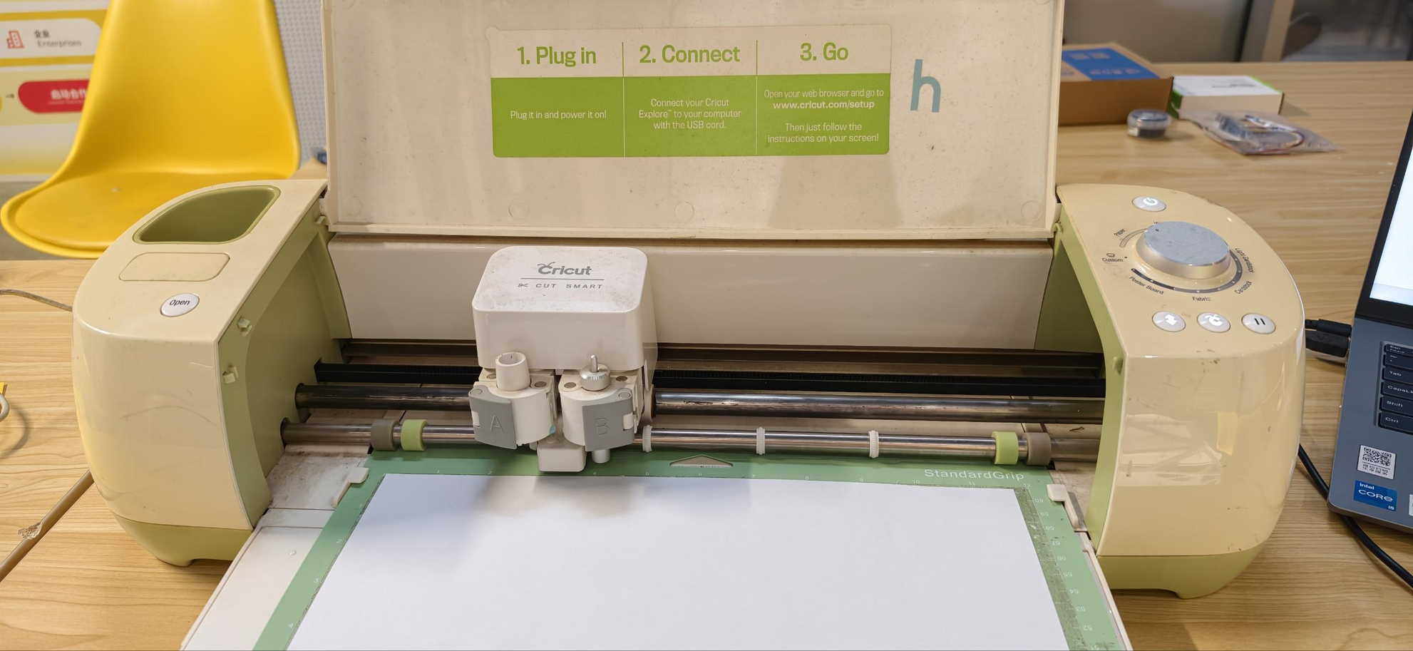
Vinyl Cutting (Cricut)
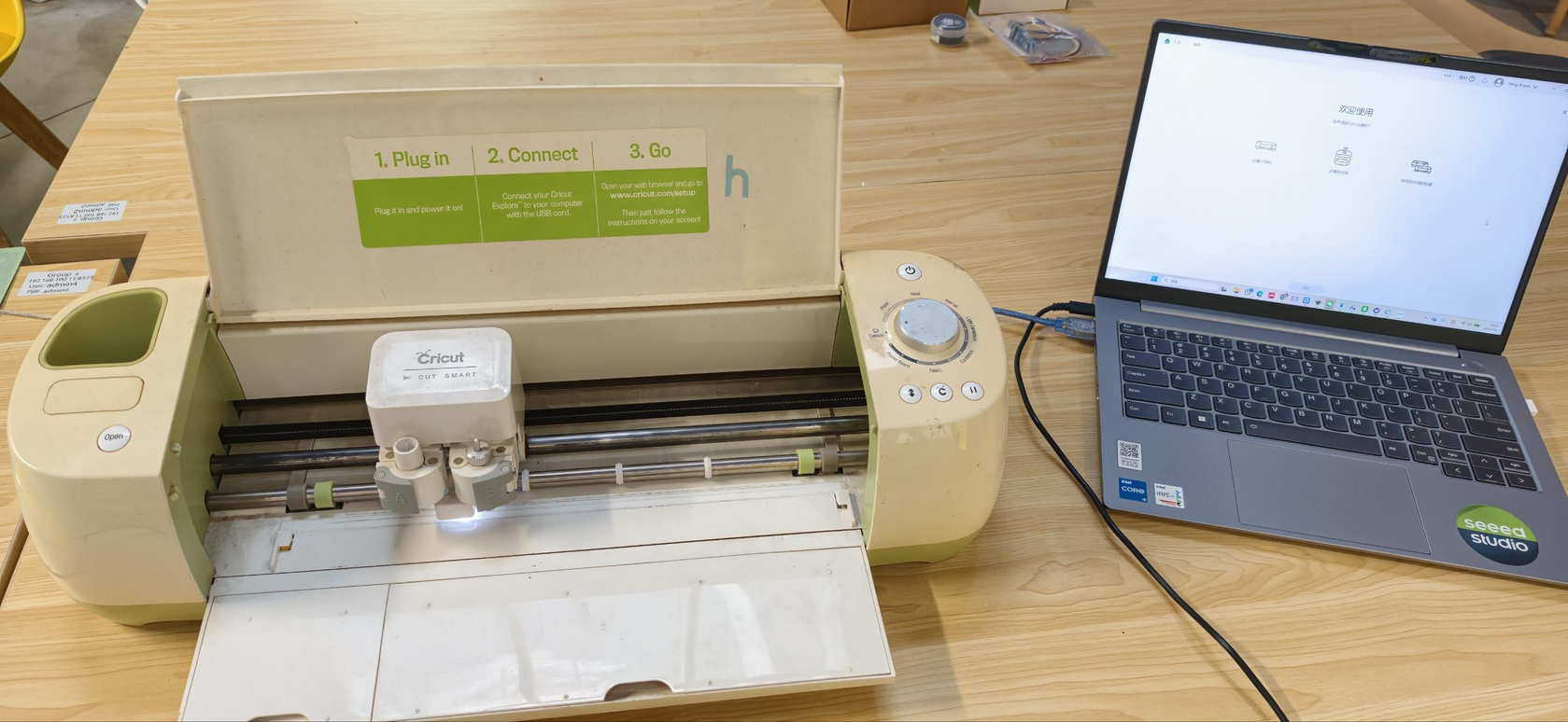
Separately, I worked through the vinyl workflow on a Cricut machine. I connected power, linked the cutter to the computer with a data cable, installed Cricut Design Space, and set up a cutting mat.
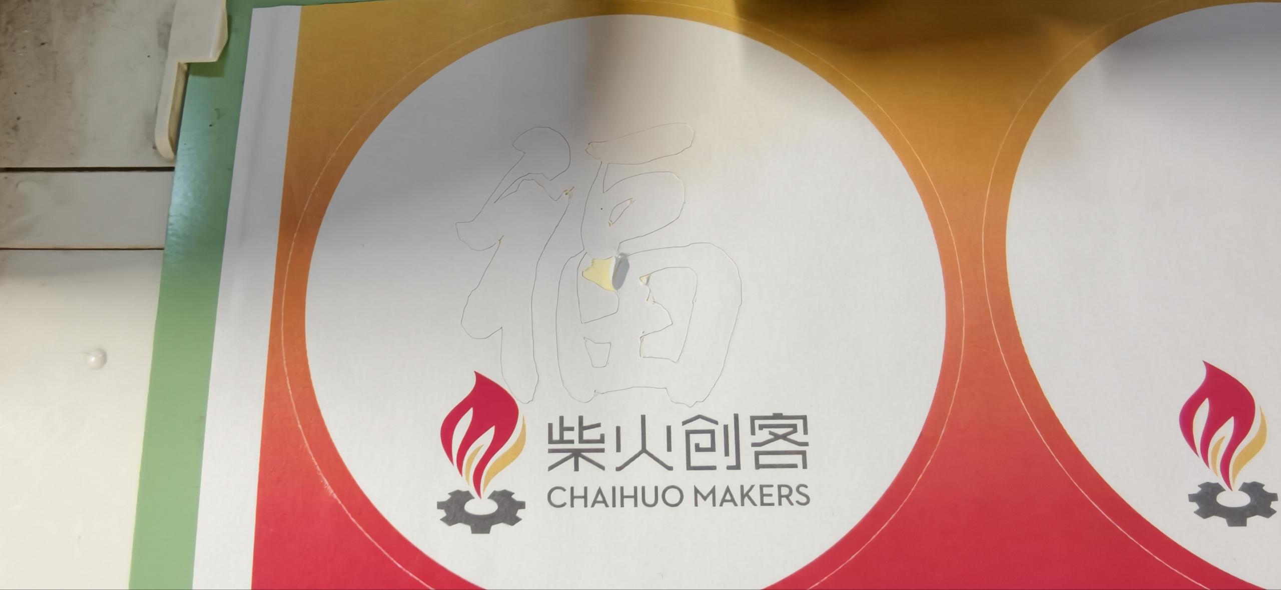
I removed the top protective film from the mat, stuck down a sheet of white paper for a first connection test, and ran the software.
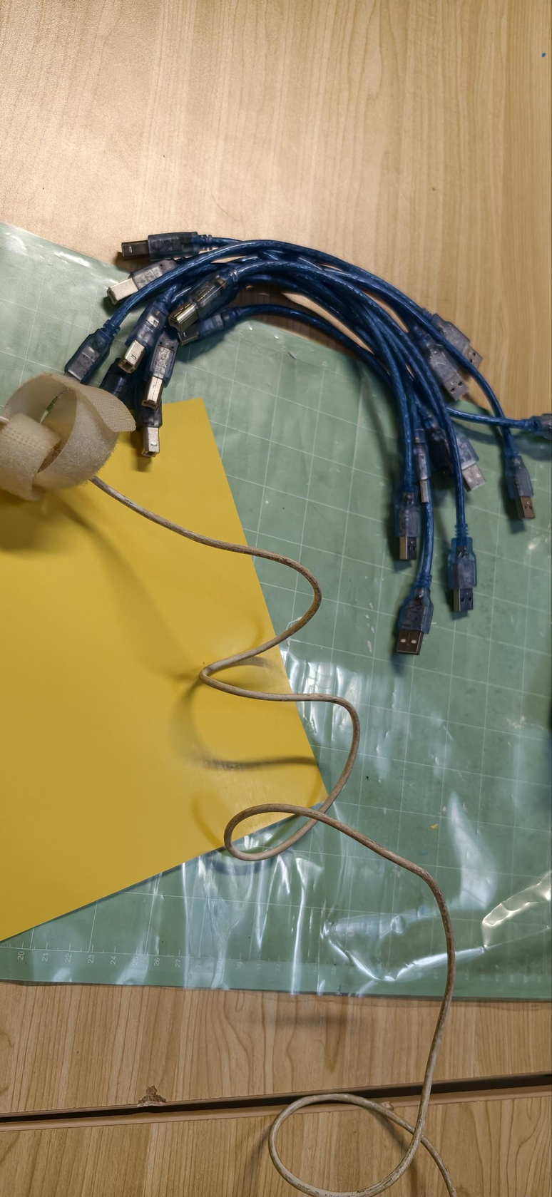
The first try failed because of a bad USB cable; after swapping the cable and restarting, the machine connected reliably.
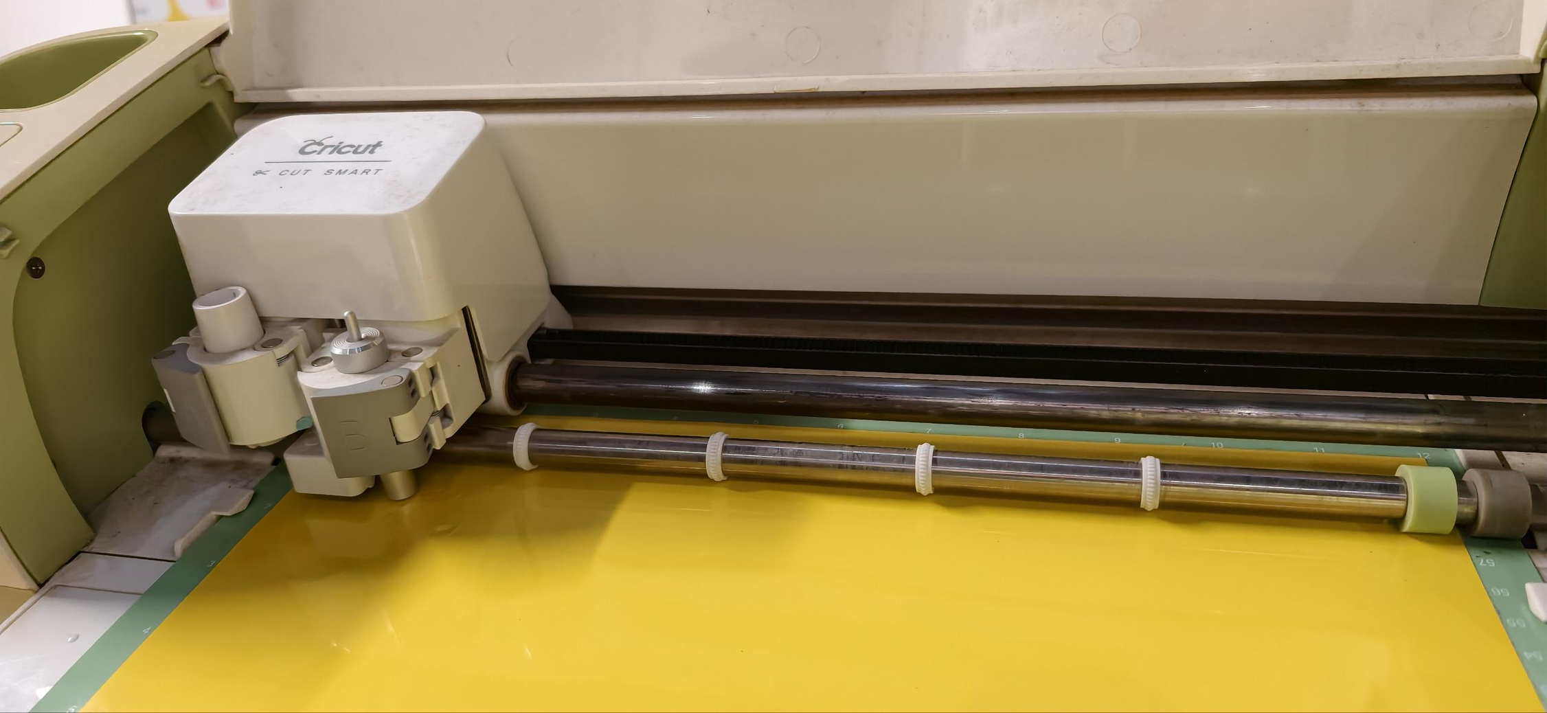
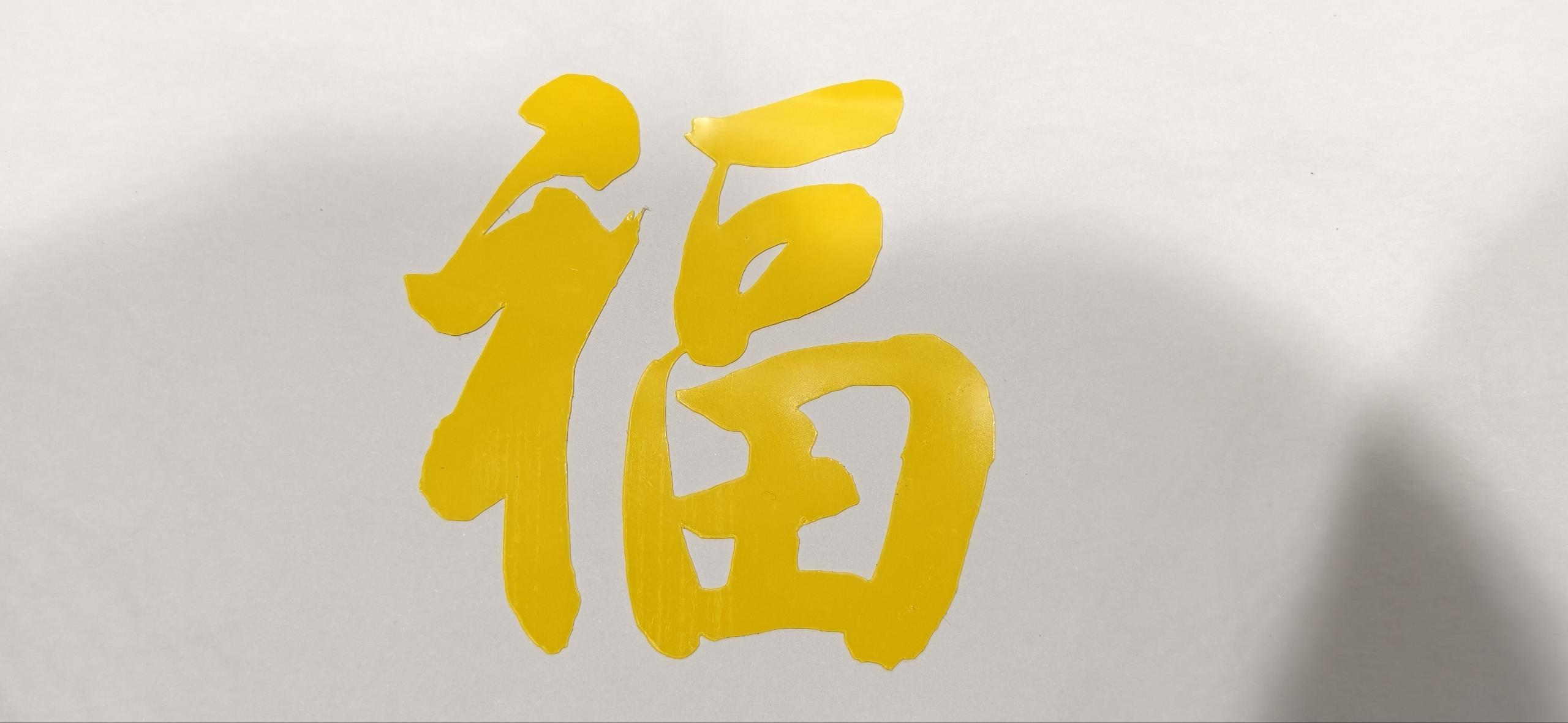
For real cuts I used yellow glass paper with decorative Fu patterns. The first two runs did not weed cleanly—some corners stayed attached.
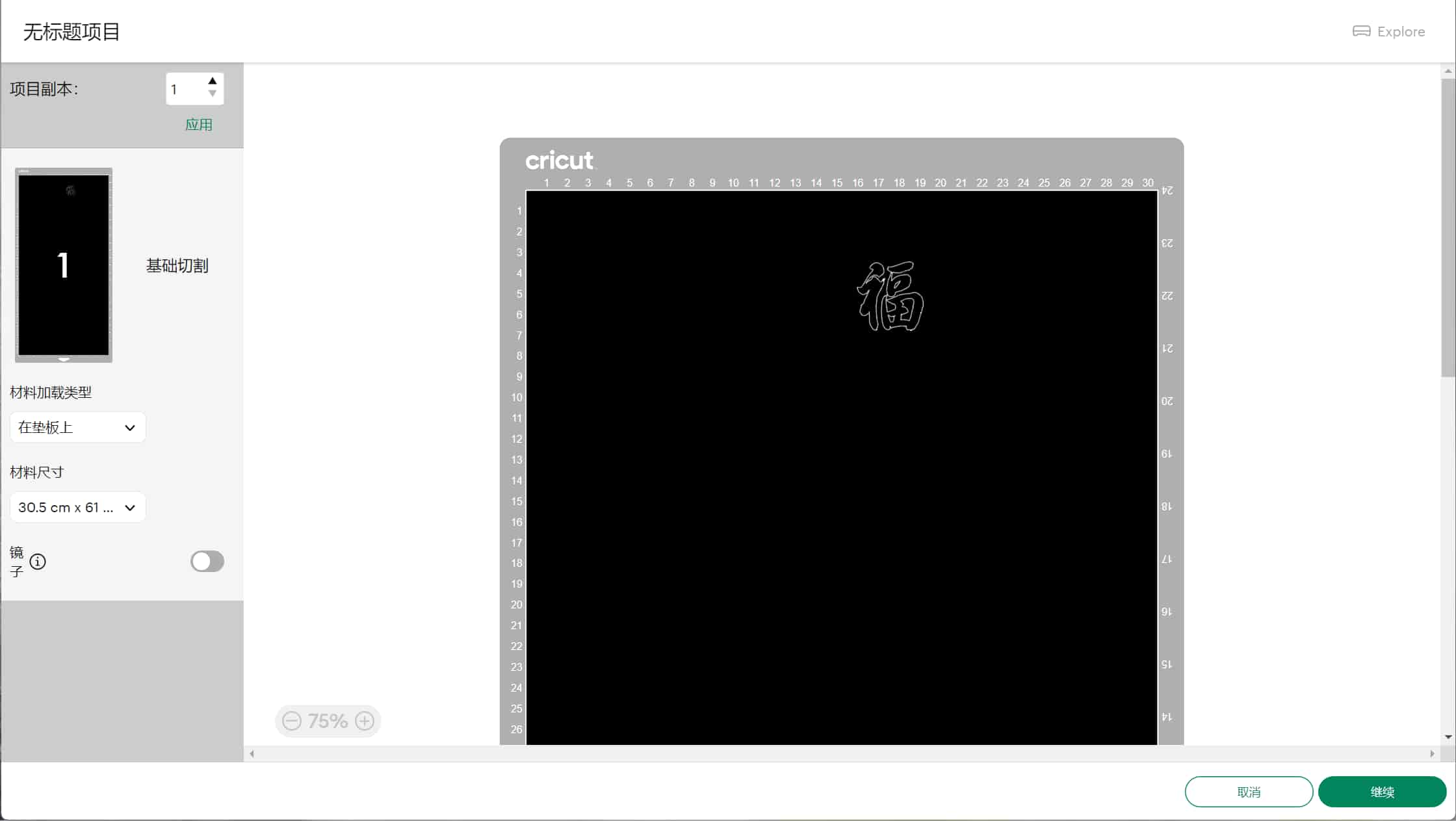
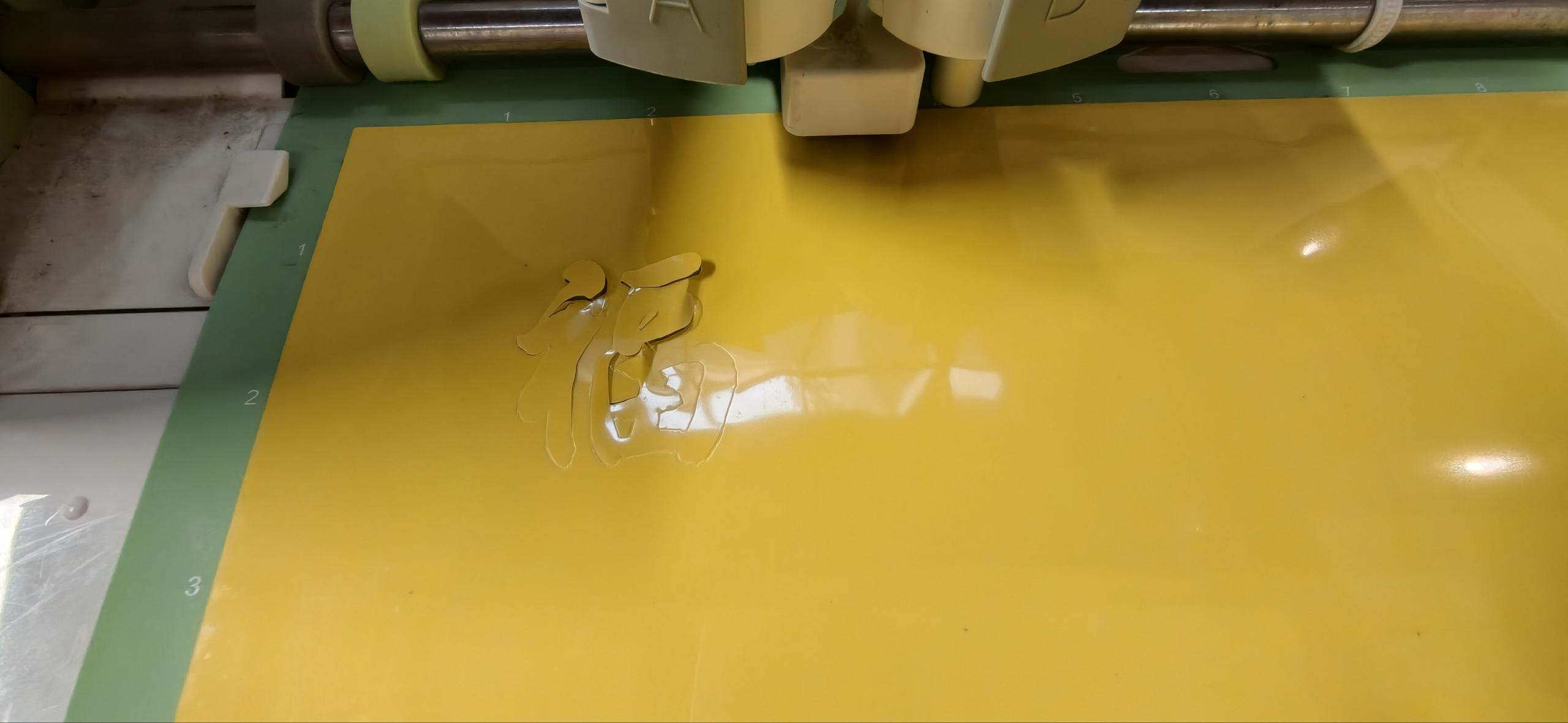
On the third try I enlarged the pattern slightly, and the cut came out clean. For a last round I switched to adhesive sticker paper, which cut very cleanly with almost no fuss. Looks very beautiful.
Vinyl reinforced the same lesson as the laser: file prep, pressure, and a bit of patience matter as much as the artwork itself.
What I Learned
This week helped me understand that cutting results depend not only on the file design, but on the relationship between:
- material thickness and consistency
- machine power and speed
- laser focus across the full cut area
- flatness of the material
- spacing and margins in the design
The kerf measurement from the group assignment turned out to be directly useful: plugging 0.15mm into the slot calculation gave a connector that fit on the first try. That connection between group characterization and individual design is exactly what the process is supposed to look like.
I also learned that small positioning mistakes in CAD show up loudly once parts have to assemble in 3D. Moving from Inkscape (illustration-focused) to Onshape (parametric, constraint-driven) is a practical step, not just a preference — it's the difference between a drawing that looks right and a model that is right.
Next Step
For the next version, I want to:
- upload all source files to the repo with clean file names
- add a photo of the Onshape parameter table to this page
- refine the full box in Onshape and verify fit before cutting
- reduce power slightly on the next connector cut to eliminate the charring
- refine the decorative pattern around the screen
- add space for the real screen, switches, and electronics
- explore traditional motifs such as cloud patterns to make the design more personal