MACHINE DESIGN
For this week, we were tasked to design and make a machine. So we divided ourselves into three groups, of which we assigned each other different roles.
One group was responsible designing mechanical structure, the other did the interface design and other one did electronics part of the design. I was
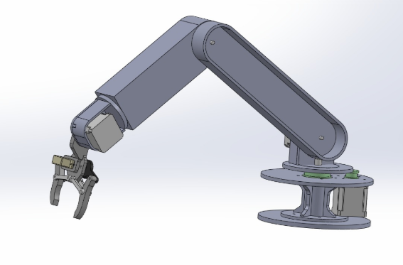
part of the team that did electronics production of the machine. The machine we did is a 5 axis robot arm.
MY INPUT
My team was tasked to design and produce electronic circuit of the machine. Below is my step by step input in fulfiling this task.
STEP 1
SCHEMATIC DESIGN
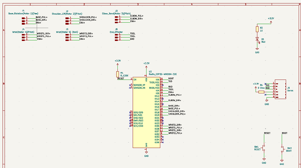
KiCad was used to design the circuit schematic, which included ESP32-WROOM-02, and connections for stepper motor drivers, pinHeader for programming through the FTDI programmer and reset and boot pins. Below is the picture of the schematic with all the connections to the stepper motors.
STEP 2
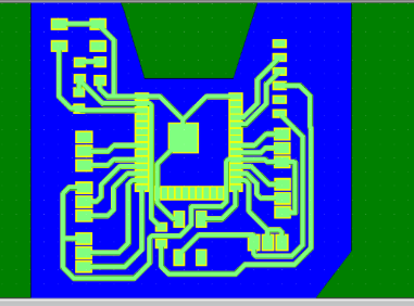
PCB DESIGN
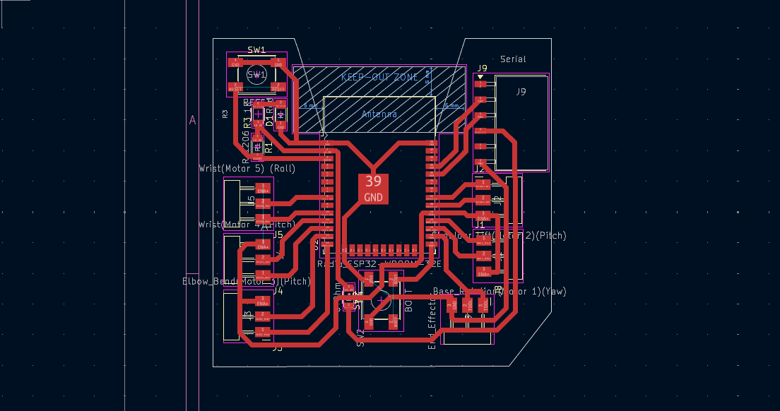
After finalizing the schematic, the PCB board layout was designed and routed, making sure that the trace widths are interferring which might lead to short circuiting. Below is the final layout of how the PCB for the machine will look like.
STEP 3
GERBER FILES GENERATION
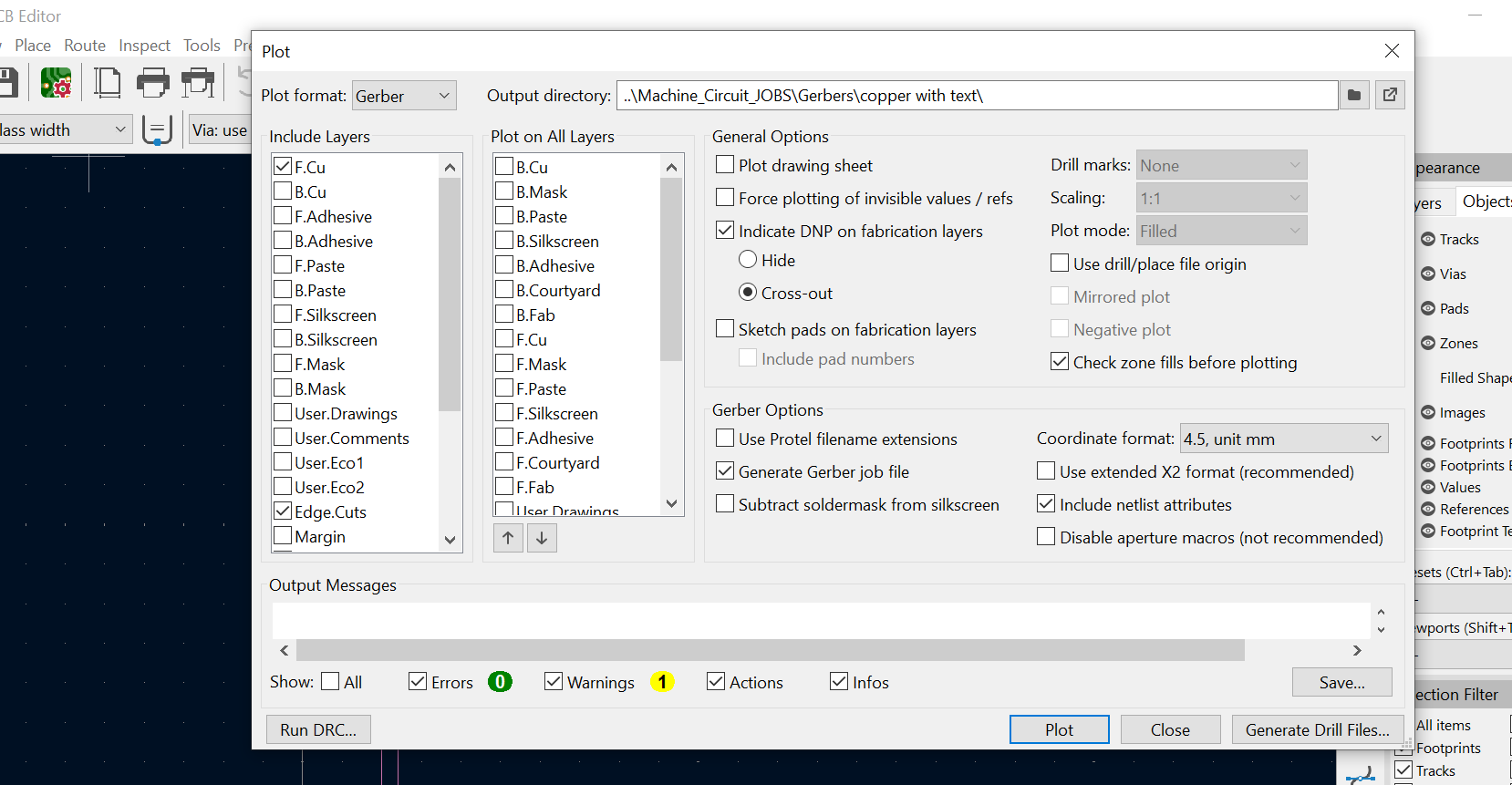
After the PCB was done then it was saved as Gerber files, which has copper layers ad edgecuts. This is to enable the creation of g-codes, so that the paths can be interpreted by the milling machine. Below is a picture which shows saving the file as gerber files.
STEP 4
CREATION OF G-CODES
The gerber files where then imported into CopperCam software to create toolpaths for milling the PCB.
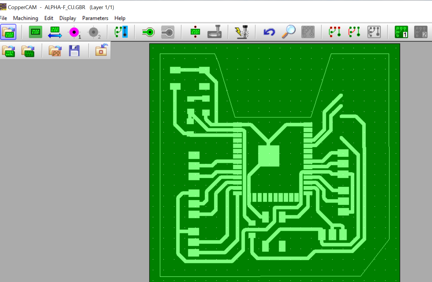
Then the tool parameters for milling this board were set. Below is how it was they were set.

Contours and hatches were calculated to generate g-code for the milling machine.
STEP 5
PCB MILLING
The g-codes created were then imported into the openbuilds software to start the milling of the pcb.
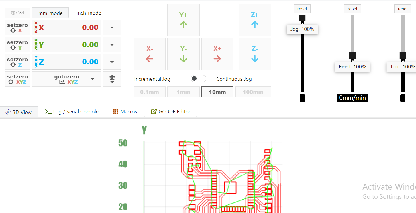
Then the milling process was began.
STEP 6
SOLDERING
The last step of pcb production was to solder the components into the milled board.
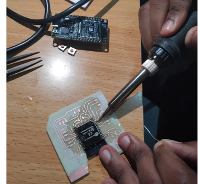
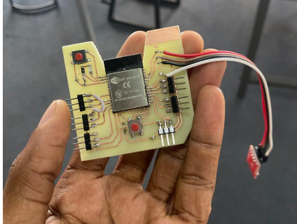
THE FINAL BOARD
FILES