ELECTRONICS PRODUCTION
GROUP ASSIGNMENT
I started this week's assignment by searching the basics of creating a PCB here site
GETTING STARTED FROM A SCHEMATIC
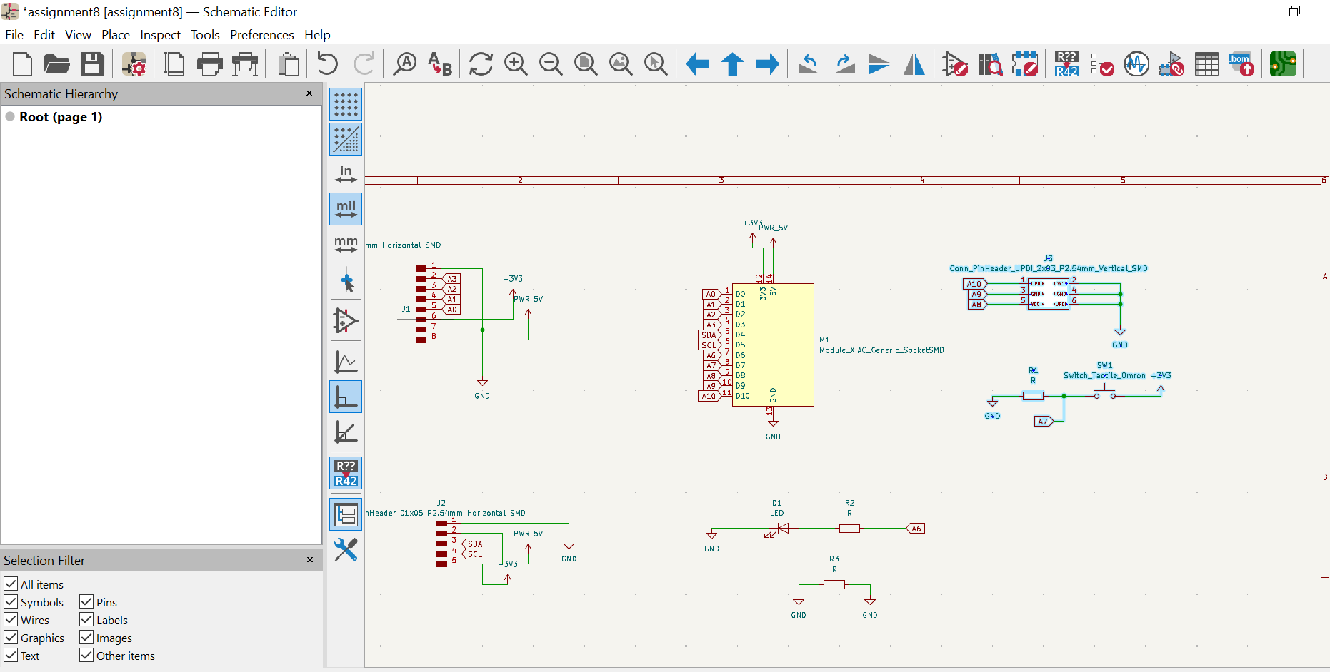
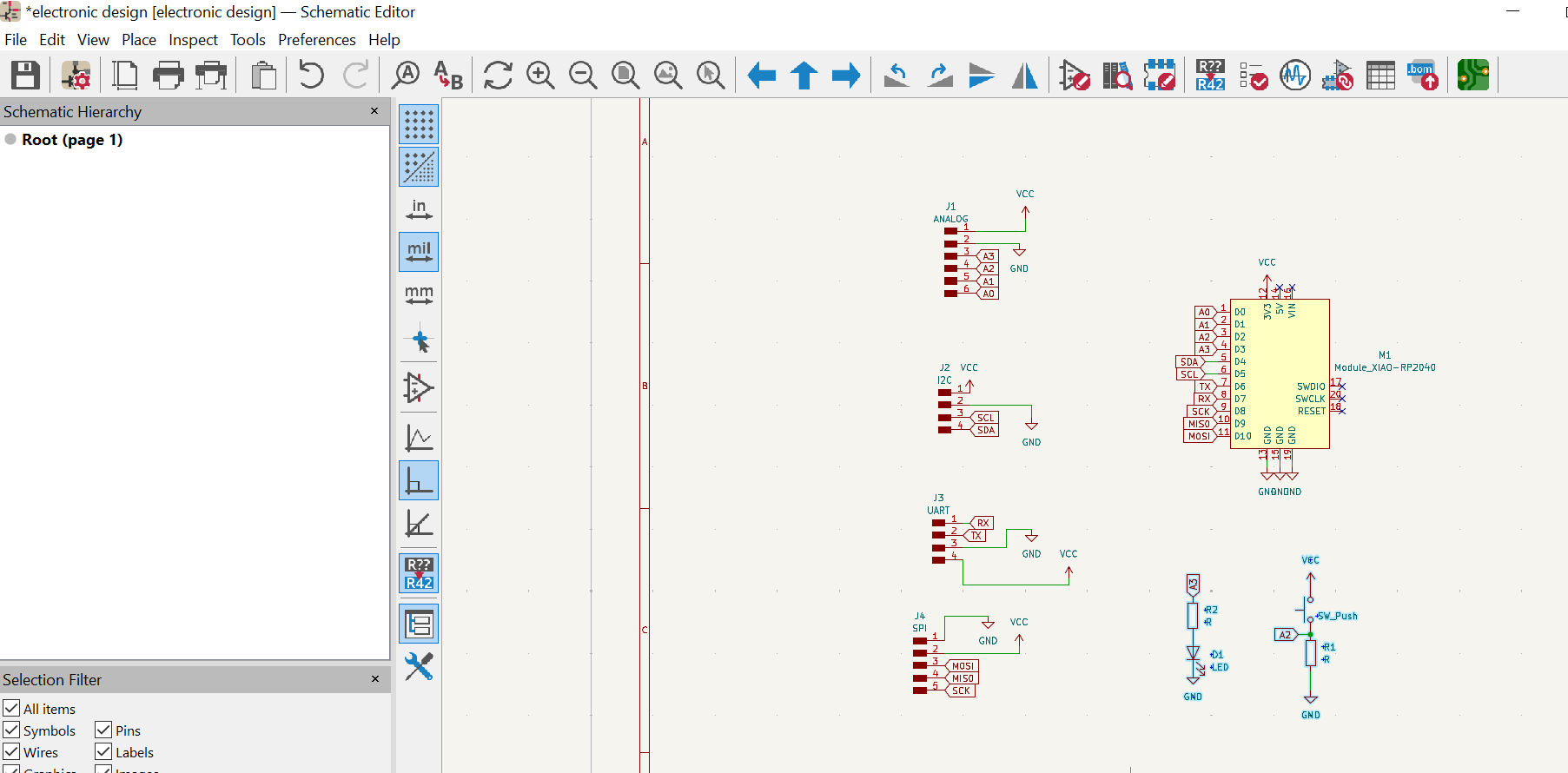
The circuit was first designed in KiCad, where a schematic was produced. KiCad was launched, created a new file and clicked schematic editor, then started adding the circuit components from the component library into the work space. The complete schematic for the circuit is shown below. The components used for the circuit are:- Xiao RP2040
- LED
- Resistors
- PinHeaders
- Switch
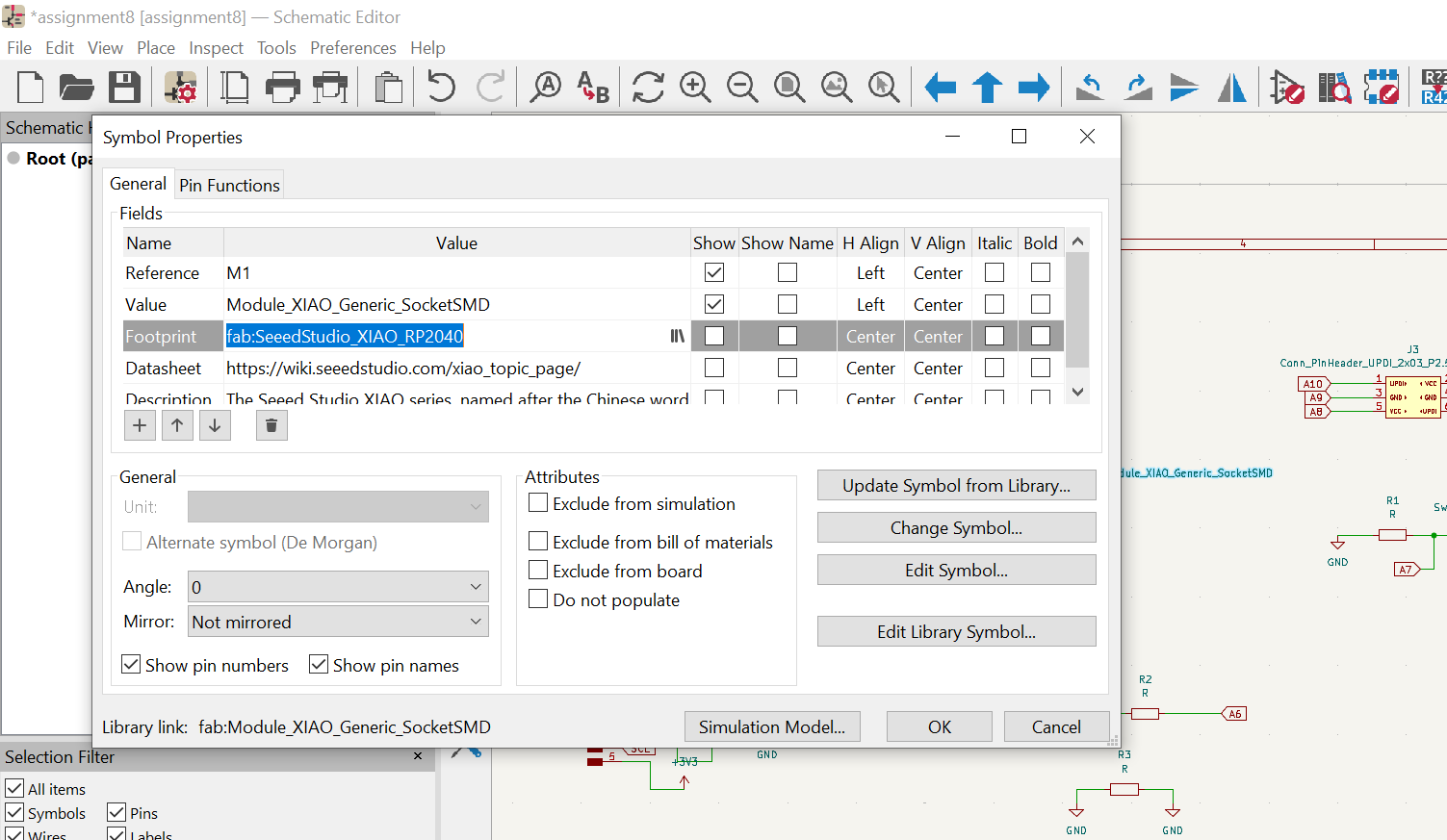
From the schematic I then assigned all the components all their footprints and then switched to
PCB editor where I updated all the components in the schematic into it and then routed it, adding tracks
of 0.5mm.
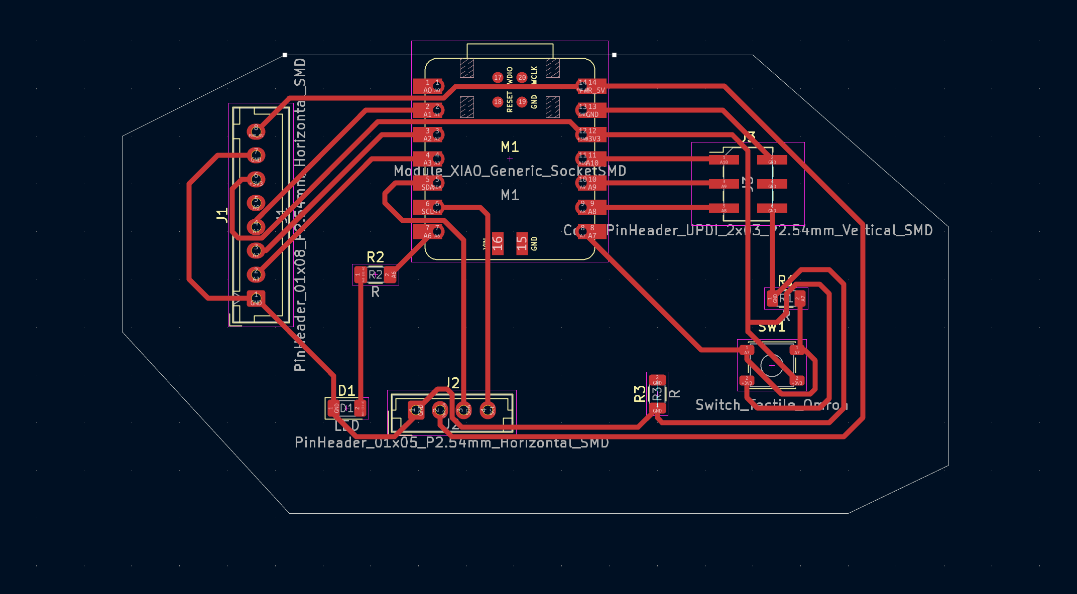
The routed PCB file was then saved as gerber files.Gerber files are the industry-standard, open ASCII vector format used to describe printed circuit board (PCB) designs, containing information on copper layers, solder mask, legend, and drill data, essential for PCB fabrication.
COPPERCAM SOFTWARE
CopperCAM software was used to make the G-Codes that are going to be used to for milling the the circuit board. The software was downloaded here and then launched. Then the gerber files was loaded into it.
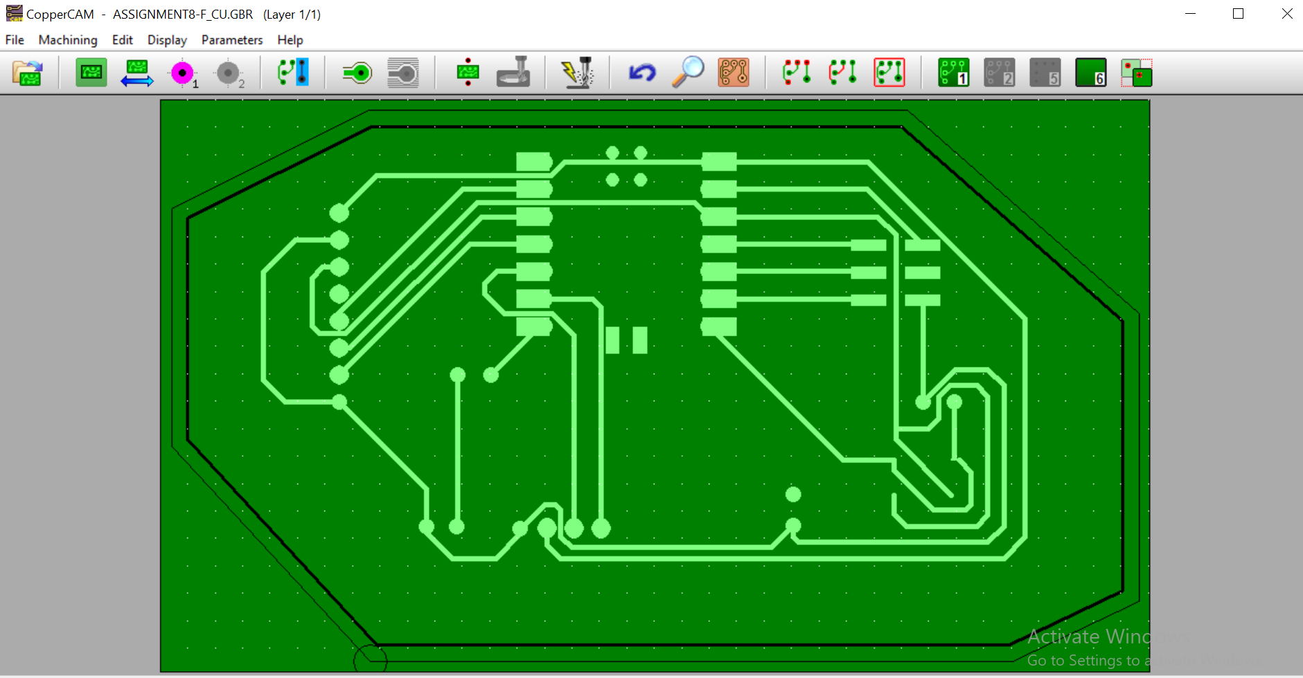
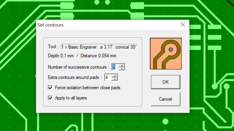
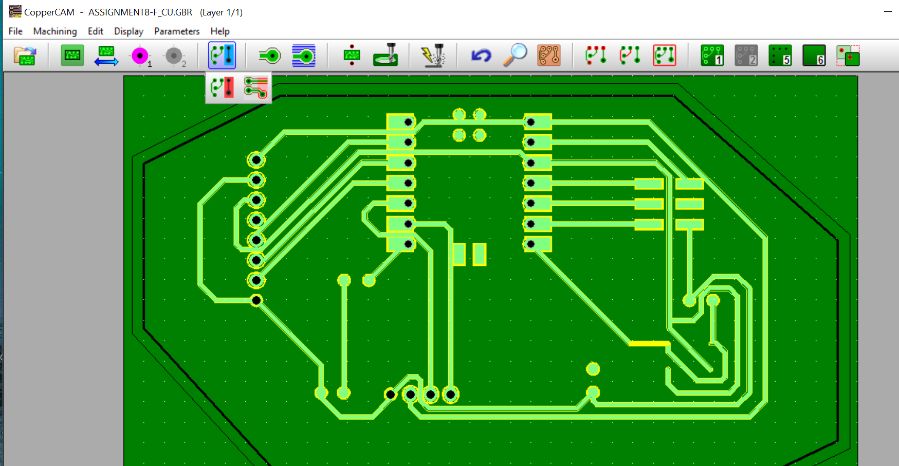
After importing the gerber files into CopperCam i the set the cutting parameters, being the contour cutting. And then then added drill file into the model.
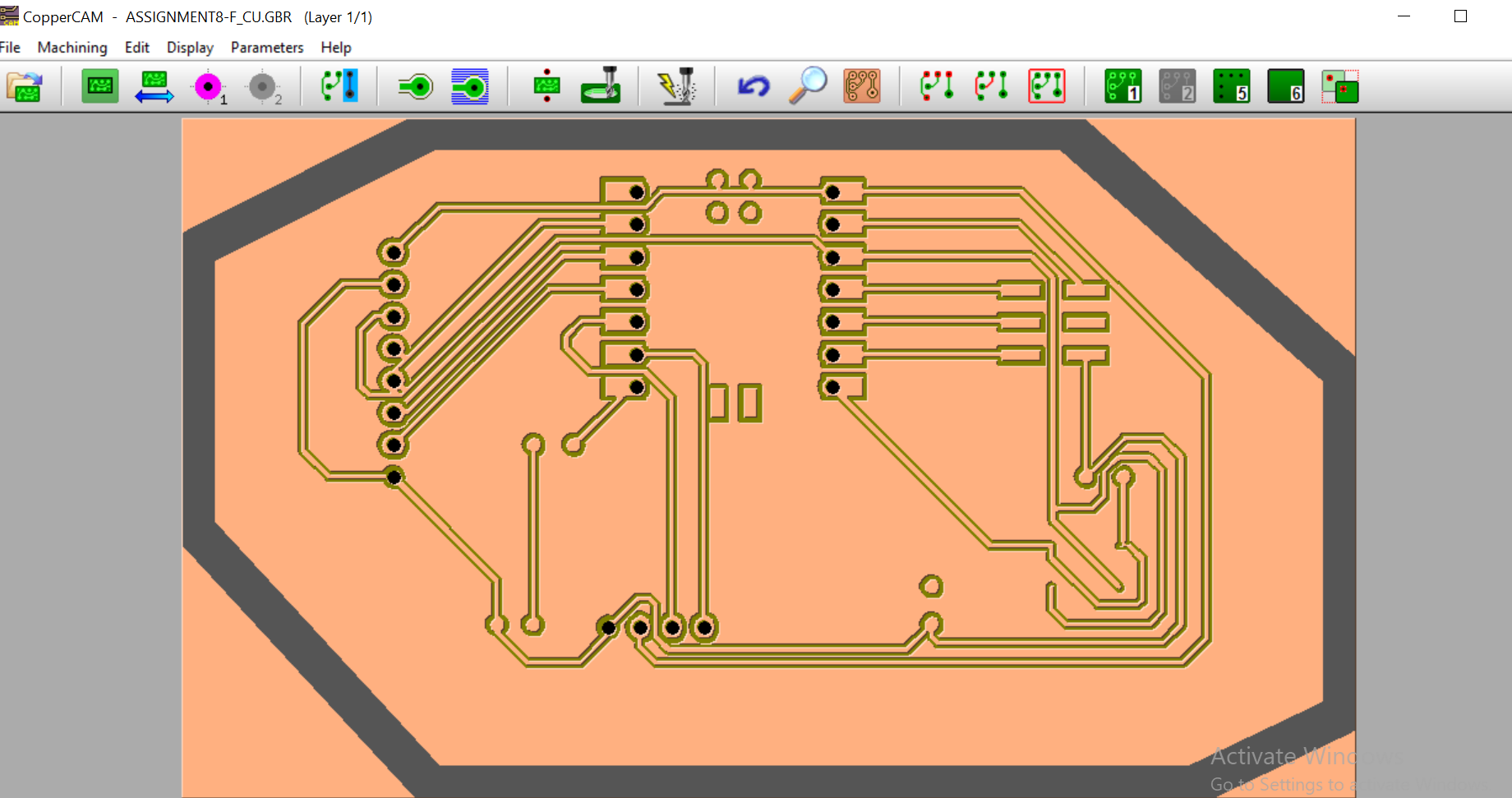
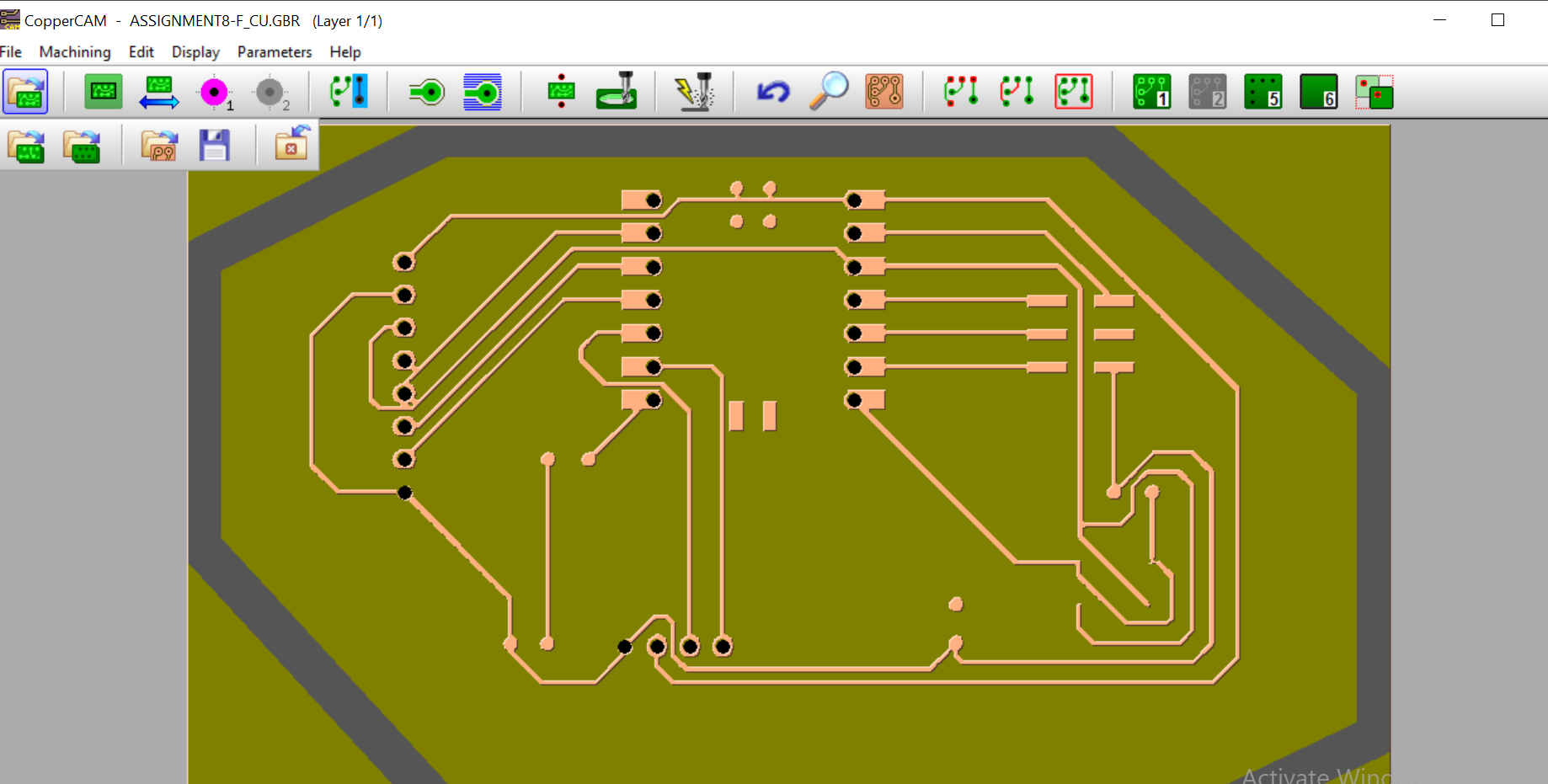
The final pcb model looked like this after everthing.
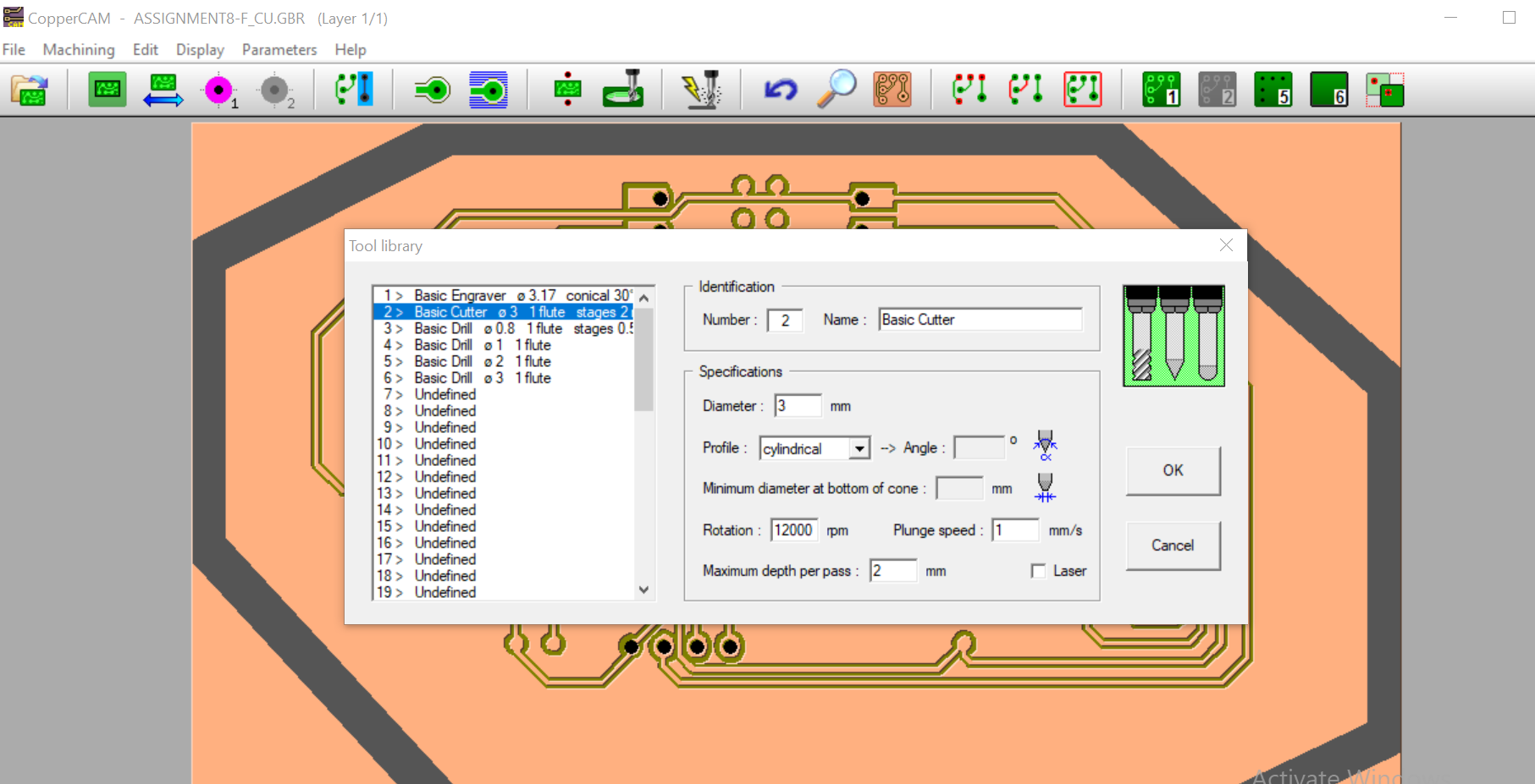
I then set the tool parameter, by selecting parameters then adding all the parameters needed for
cutting the board.
The final booard will look li this.
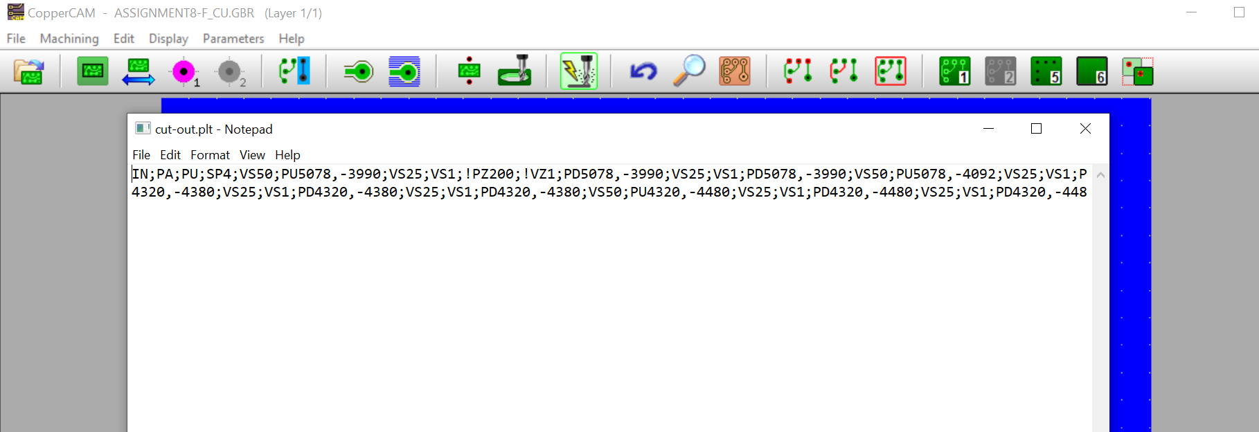
The mill button was clicked to create the G-code readeable by the machine to be used to cut the PCB
PCB MILLING
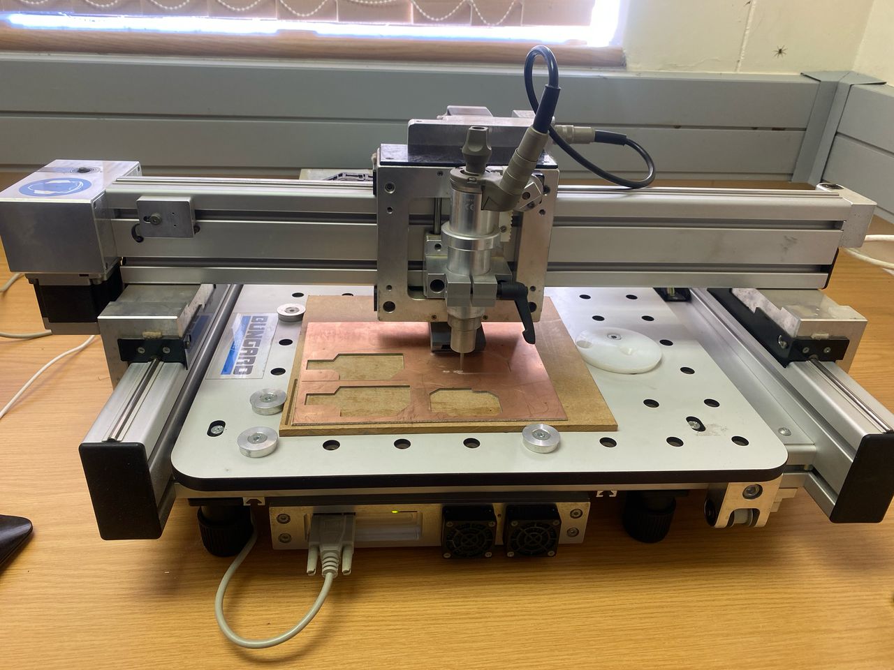
For milling the PCB I used the Bungard CCD/2 Eco milling machine.
RoutePro3000 SOFTWARE
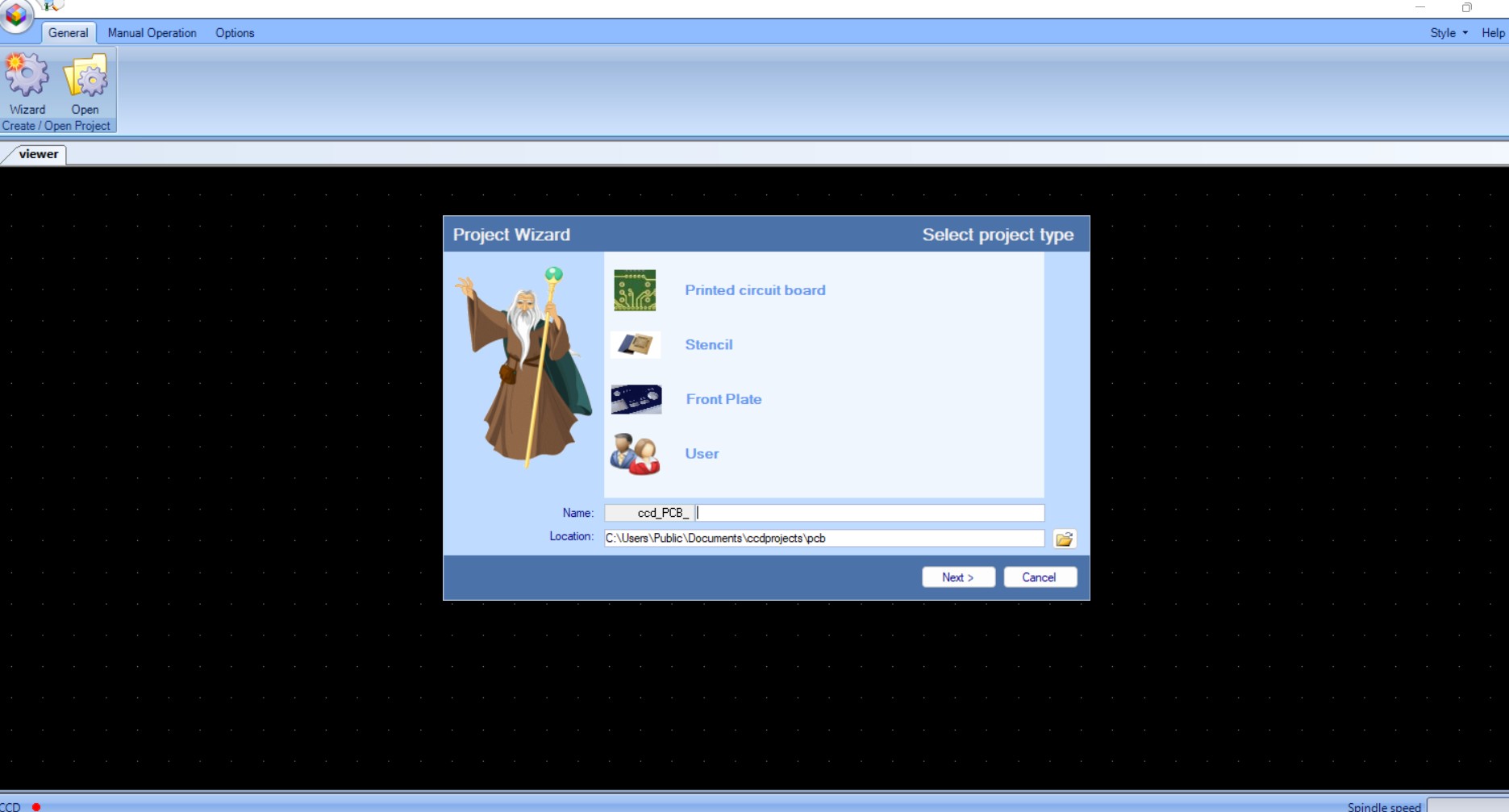
I then used RoutePro 3000 which is a software build for running the BUNGARD CNC systems. THe software was downloaded here and then installed and launched.
New project button was then clicked and then imported the .plt files from coppercam into it
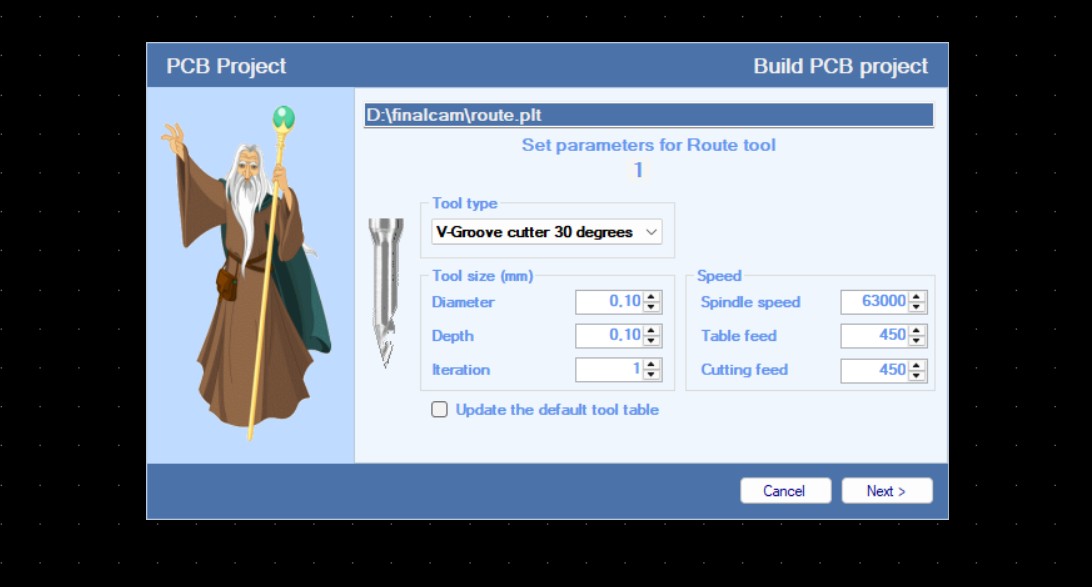
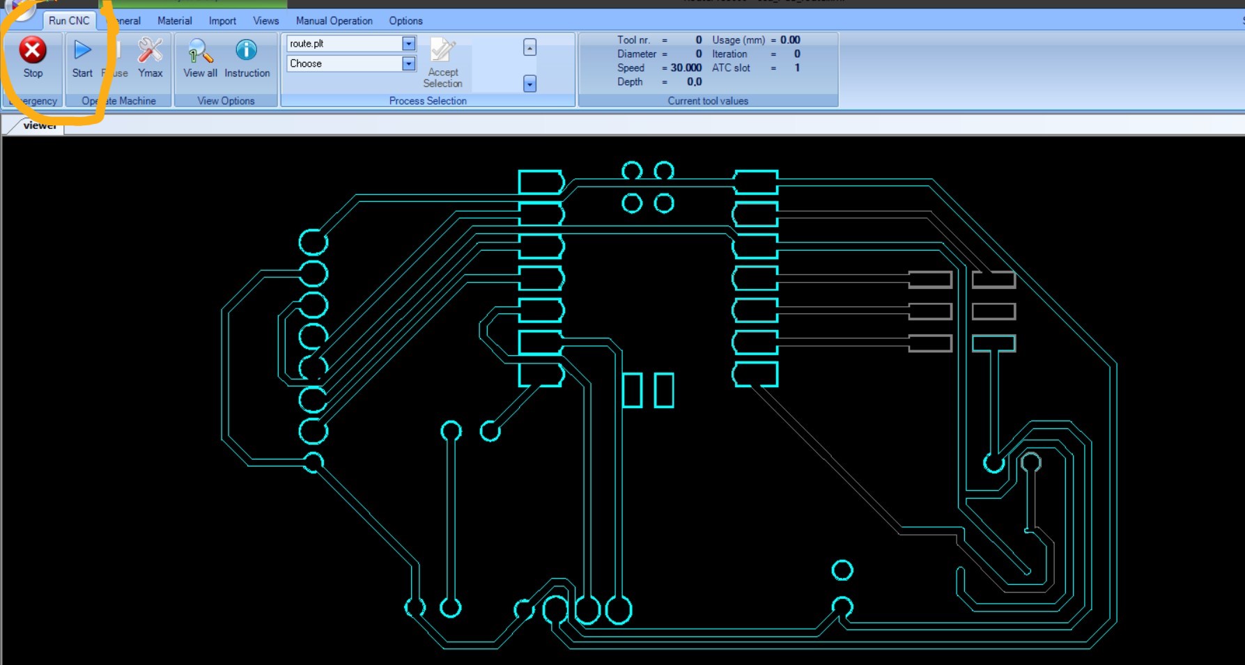
All the the .plt files, route, drill and cut out were imported into the software and the material, tools, diameter, depth and iterations for each file were assigned/set.
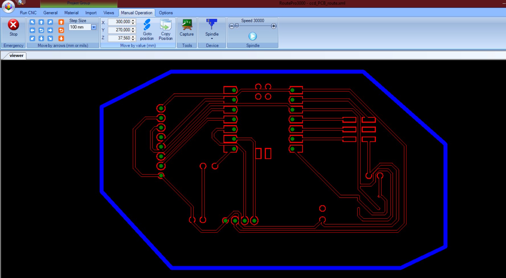
After importing all the files this is how the file looked, showing the track paths, drill holes and cut out path in blue.
LOADING THE MATERIAL
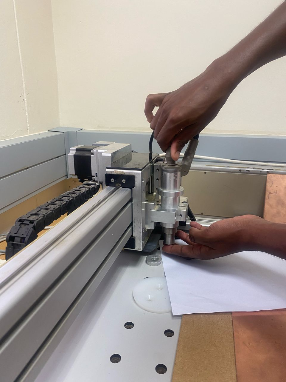
The material(FR-4) was then loaded into the machine being held with a double sided tape to avoid it from moving as it is being milled.
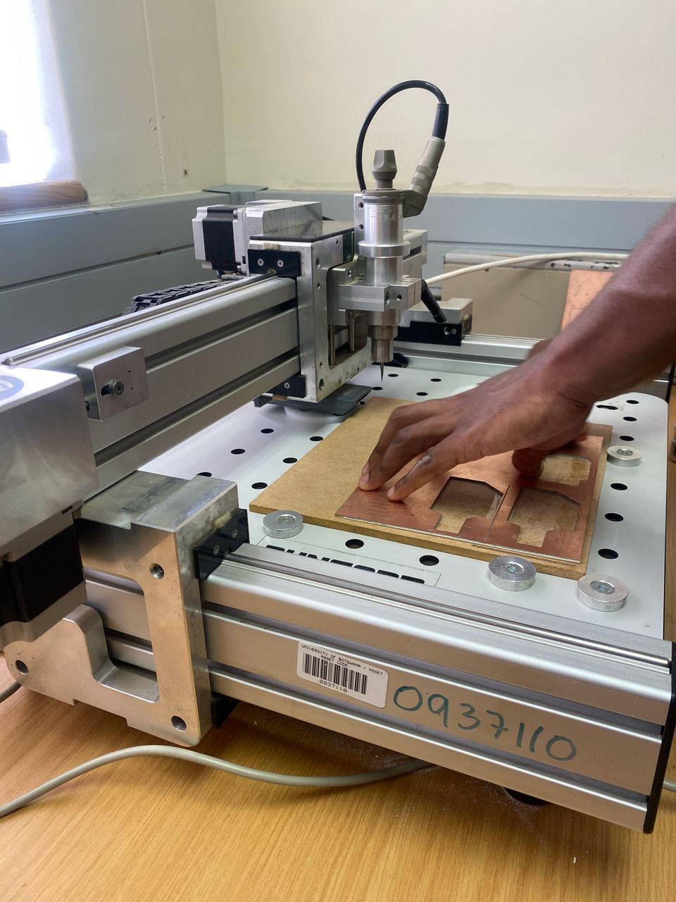
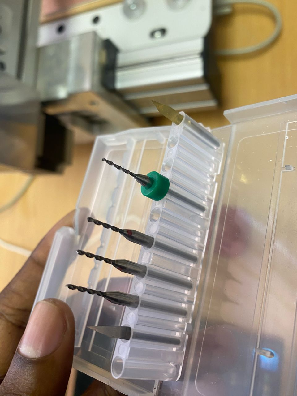
The tool was inserted after loading the material. Each file had its own tool and the tools were changed every after the milling process for one file was complete.
After everything was set I then clicked the run button to start the milling of all the files.
After milling the PCB was removed from the machine then cleaned with a P1000 sandpaper. I looked like this after after everything was done.

FILES
STARTING AFRESH
After realizing that the pcb I have milled some of the parts where left out I then restarted the whole process with some corrections and differences here and there.
SCHEMATIC
I started reproducing a new schematic with the same components, assigned labels and then assigned the footprints.
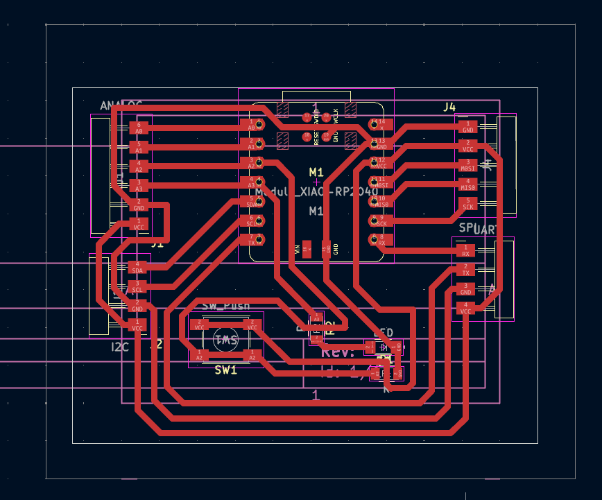
PCB DESIGN
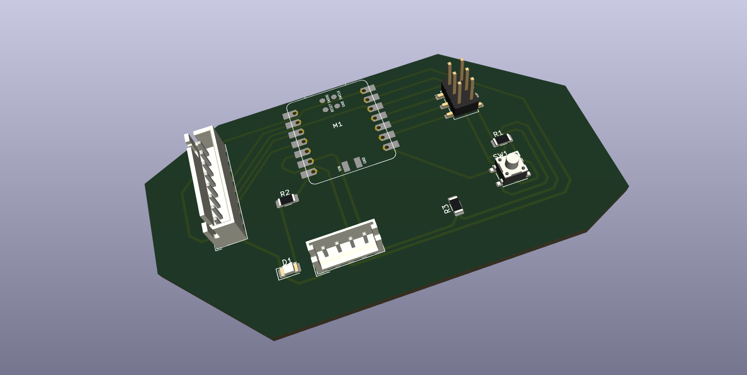
I then moved the schematic to pcb editor, by clicking the pcb editor button then updating all the schematic components into it. I then routed with track thickness of 0.8mm, and the final pcb design looked like this:
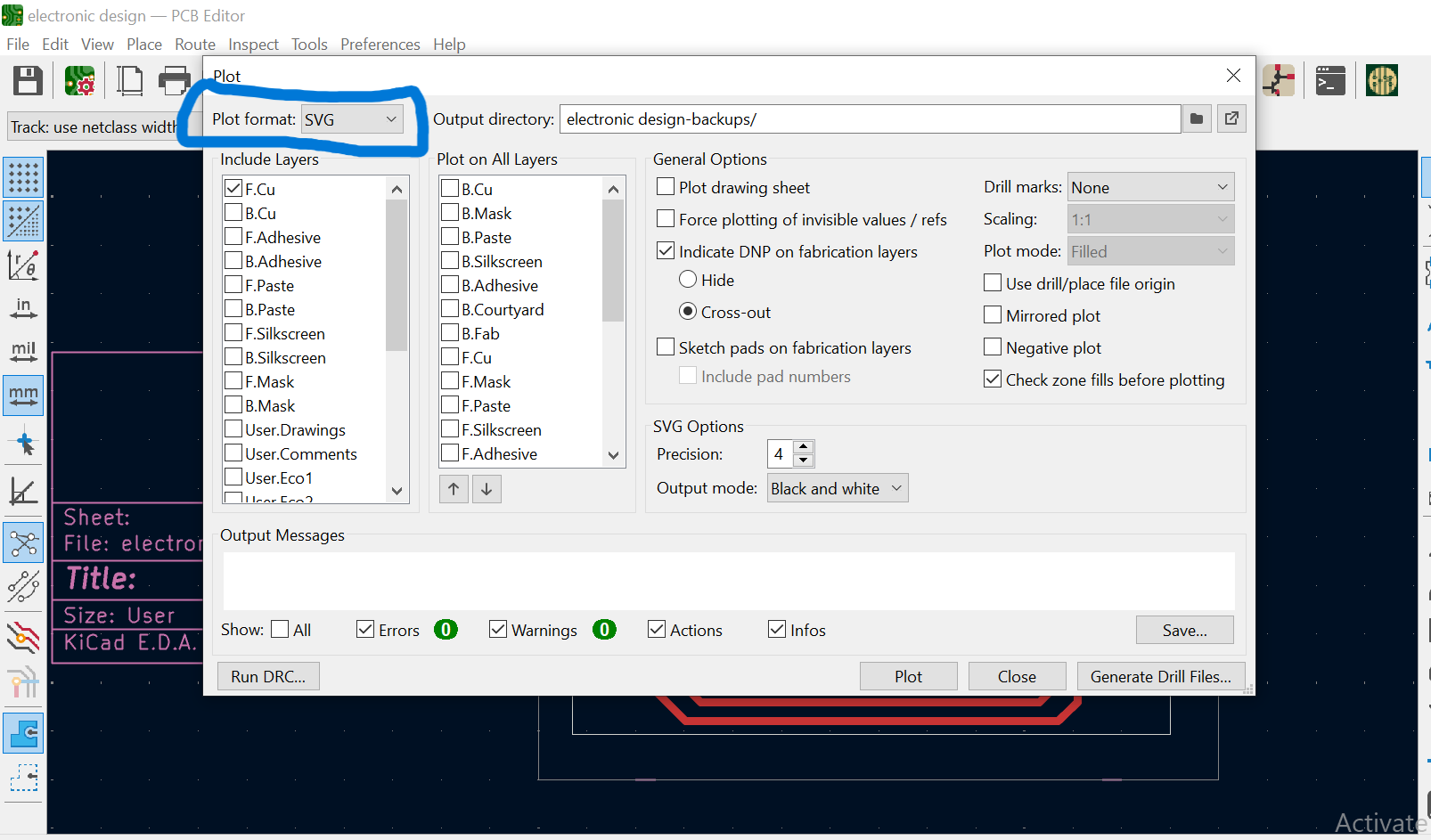
PLOTTING
I clicked the file menu then clicked plot, this was to create necessary file that will be used for manufacturing the board. The plot option allows one to create different files which are gerber files, SVG files, Drill files and position files, of which I used SVG file, to be able to trace my tracks,(F.Cu) and Edge cuts.
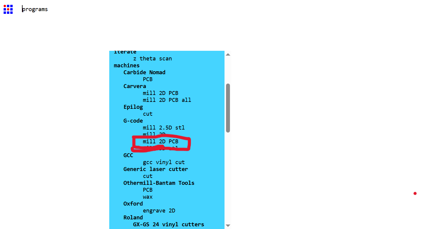
CREATING G-CODES
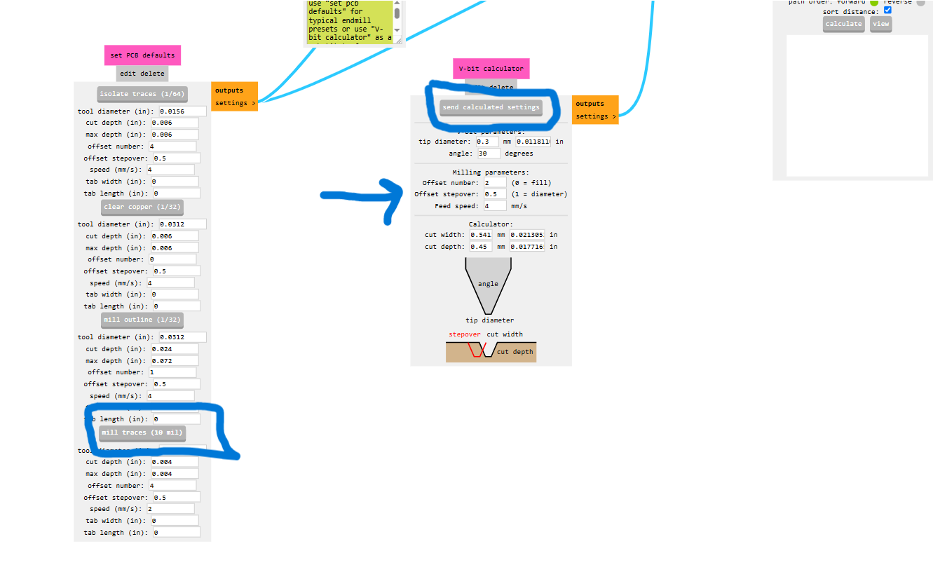
To create files readable by the machine I went into modsproject opened a new program, then selected mill pcb 2d under the g-code option, and then imported the tracks ((F.Cu).svg) file into it.
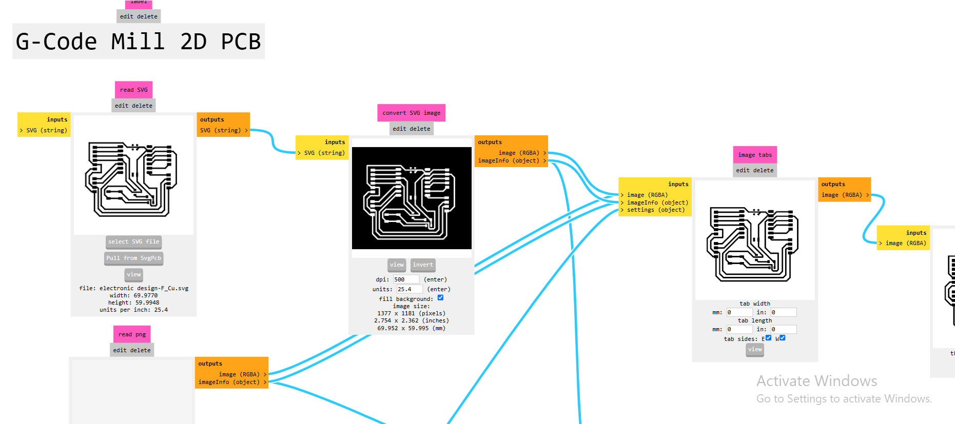
I then selected mill traces under set PCB defaults and then moved to set bit sizes and cut depth and then clicked send calculated settings.
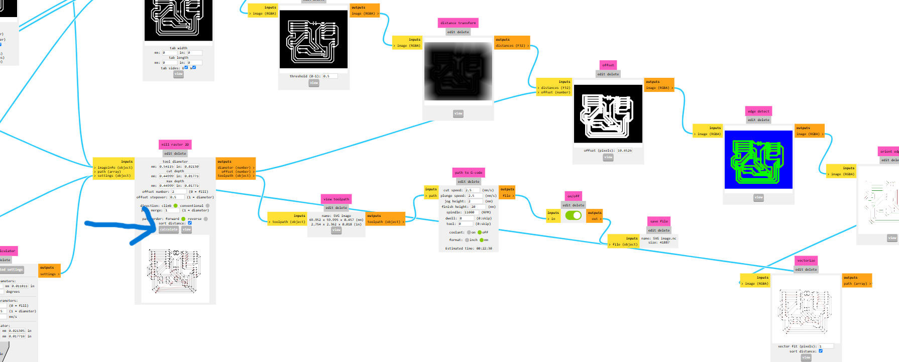
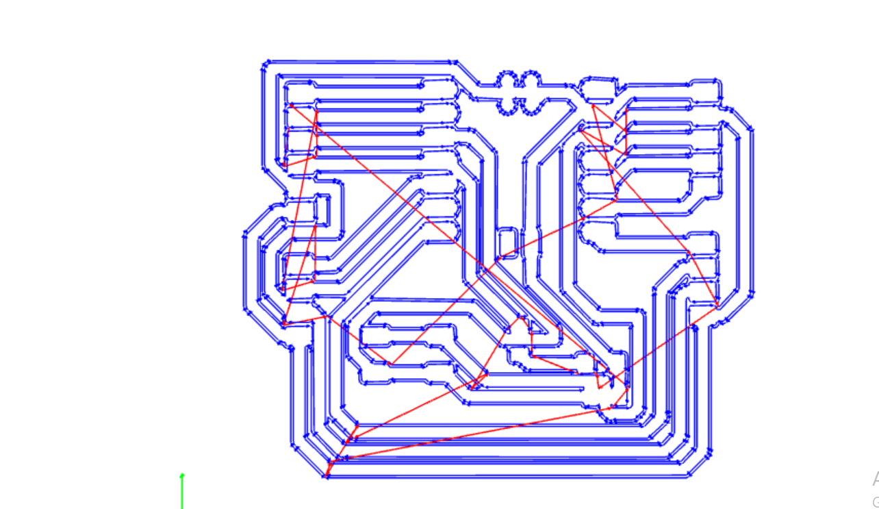
The final tool path for the milling of the PCB looked like this:
MILLING THE PCB
For the process of milling the pcb, I started off by installing openbuilds software here. And then launched it and openned the g-codes from modsproject into it.
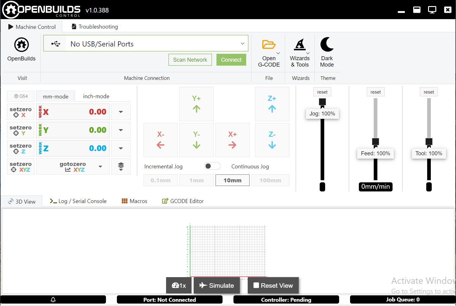
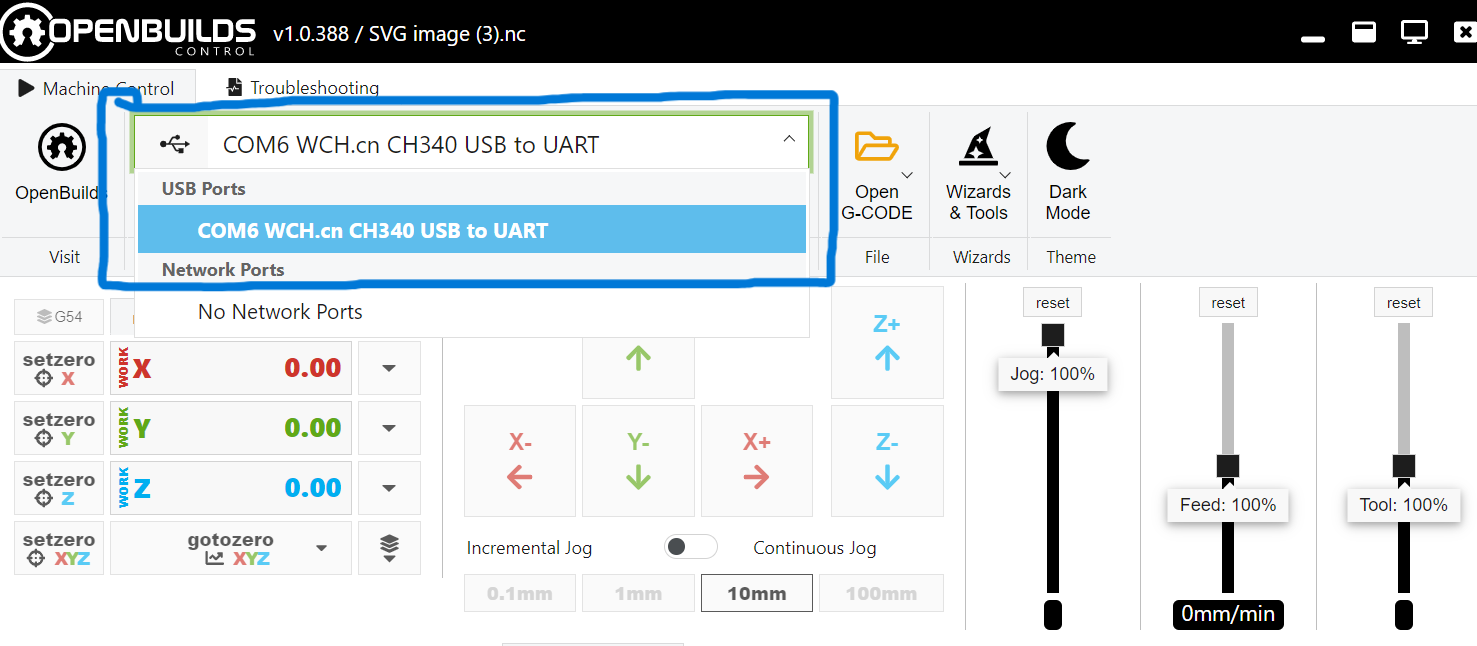
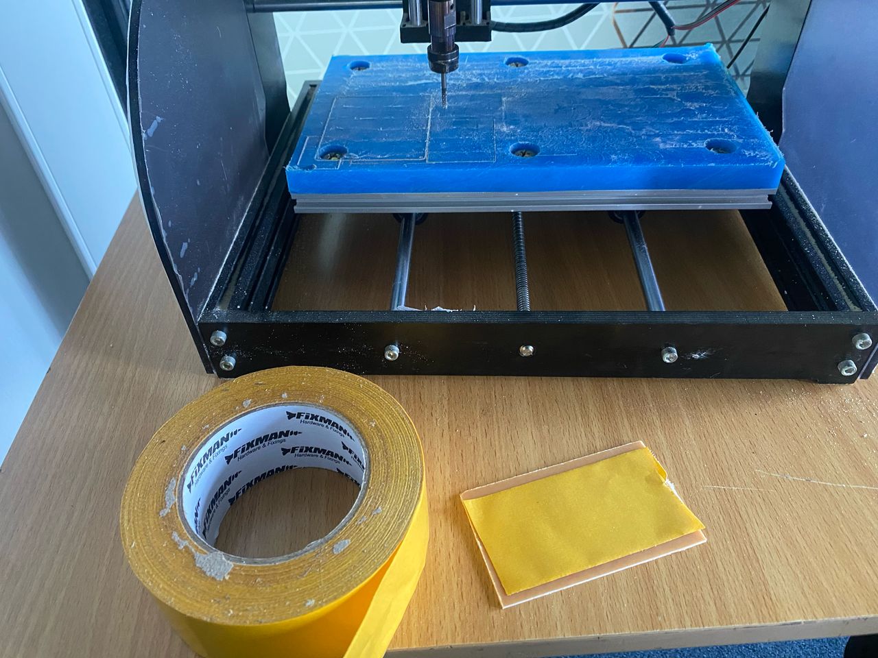
The machine was connected and made sure it appeared in the software. Then the pcb was fixed into the machine table with double sided tape to hold it firmly so that it does not move. Then the pcb milling was begun.
Connecting the software to the milling machine.
Fixing the FR-4 board to the machine using a double-sided tape.
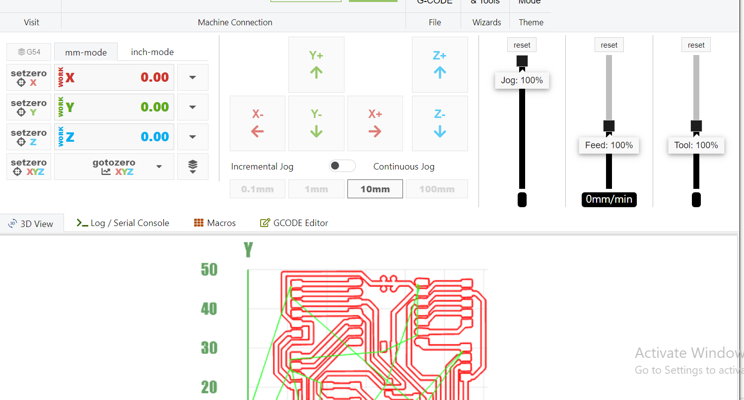
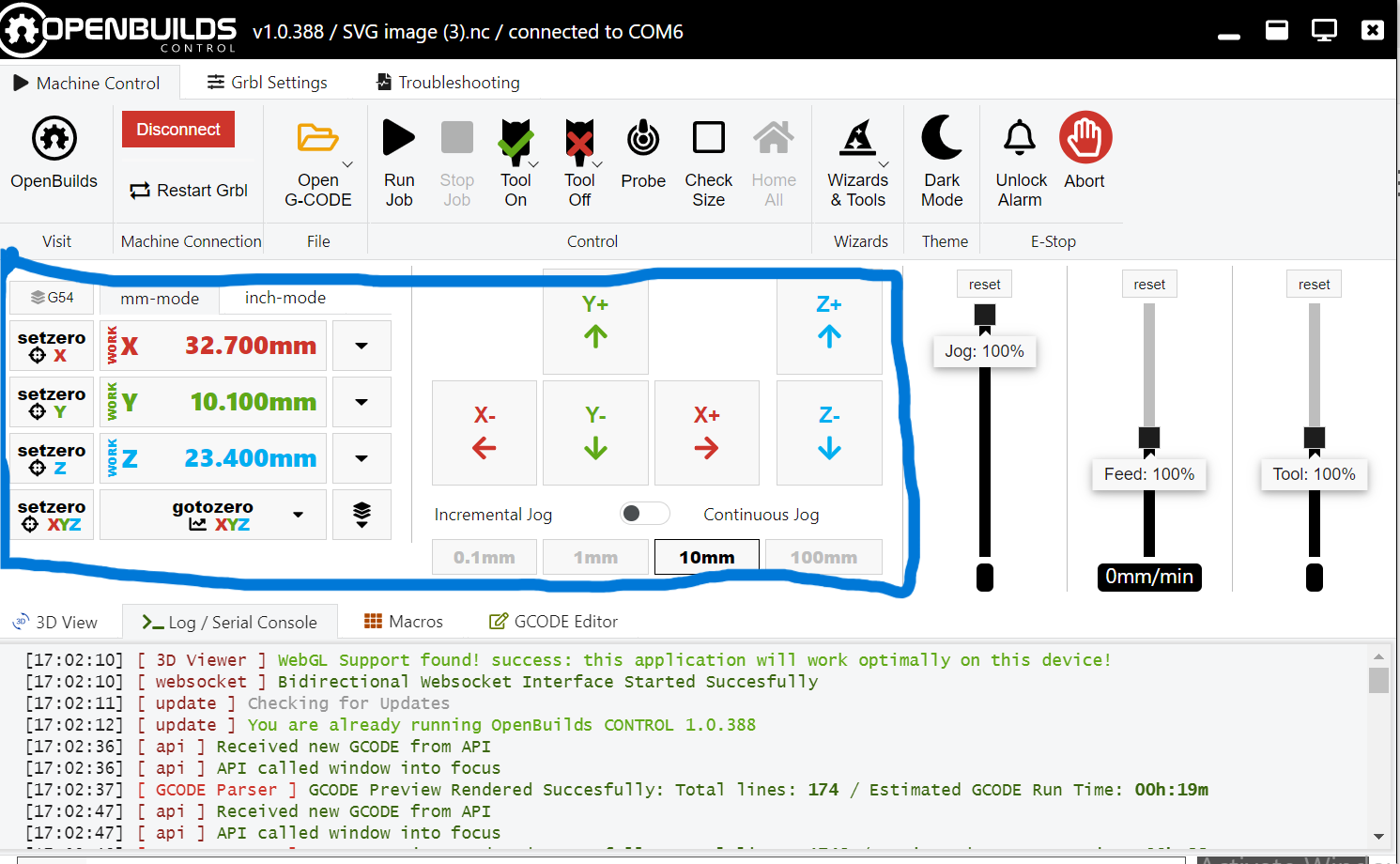
Setting the machine zero using the highlighted buttons on the software.
milling
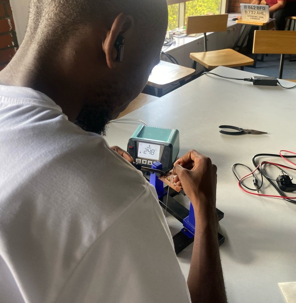
After milling the components where then soldered into the board
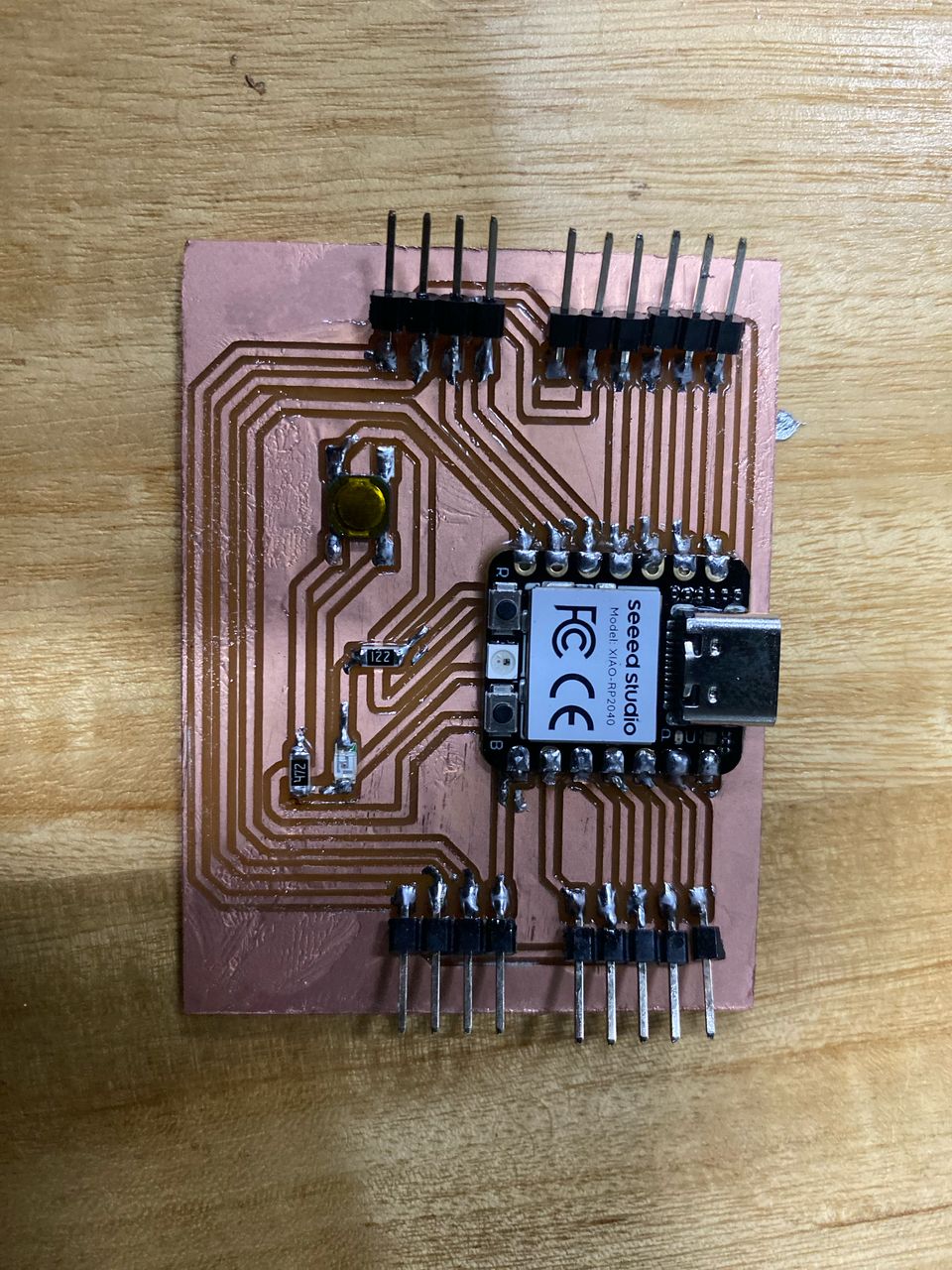
And final PCB looked like this:
TESTING THE PCB
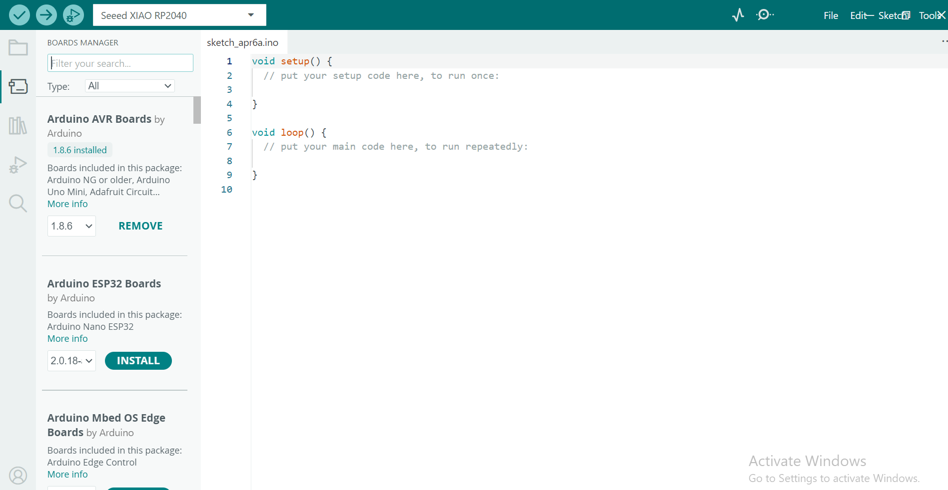
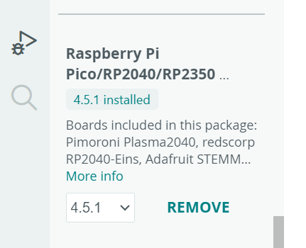
For testing the pcb made, I started off by downloading the Arduino IDE on this Website and then installed it. I also installed the boards libraries into the software.
I then created a single code to test my pcb in the arduino ide. The test was to blink an LED.
const int ledPin = 29;  // Declare the pin at the top, so all functions can use it

void setup() {
  pinMode(ledPin, OUTPUT);  // Set pin as output
}

void loop() {
  digitalWrite(ledPin, HIGH);  // Turn the LED on
  delay(500);                  // Wait for 500ms
  digitalWrite(ledPin, LOW);   // Turn the LED off
  delay(500);                  // Wait for 500ms
}