COMPUTER CONTROLLED CUTTING
WHAT IS COMPUTER CONTROLLED CUTTING?
Computer controlled cutting is a manufacturing process that uses a computer to control a tool cuts the material.
TYPES OF COMPUTER CONTROLLED CUTTING MACHINES
LASER CUTTER
A laser cutter is a prototyping and manufacturing tool used primarily by engineers, designers, and artists to cut and etch into flat material. Laser cutters use a thin, focused laser beam to pierce and cut through materials to cut out patterns and geometries specified by designers.
CNC ROUTER
A computer numerical control (CNC) router is a computer-controlled cutting machine which typically mounts a hand-held router as a spindle which is used for cutting various materials, such as wood, composites, metals, plastics, glass, and foams. CNC routers can perform the tasks of many carpentry shop machines such as the panel saw, the spindle moulder, etc. They can also cut joinery such as mortises and tenons.
VINYL CUTTER
A vinyl cutter is a machine that uses a blade to cut designs into vinyl and other materials. It's similar to a printer, but instead of ink, it uses a blade to cut shapes and letters.
ASSIGNMENTS
This group assignment made me realize that Kerf should be considered for when designing things to be laser cut , as this is important especially when working on high tolerance projects for example, gears. From now on, I will always include an allowance for Kerf on my laser cut designs.
INDIVIDUAL ASSIGNMENTS
DESIGN AND LASERCUT A PARAMETRIC PRESS FIT CONSTRUCTION KIT
Parametric design is based on defining parameters, or in other words, data inputs that are connected with modeled objects. When adjusting one parameter, such as changing the number of columns or extending the width of a deck, all of the model objects affected by that change are automatically updated.Parametric design differs greatly from traditional 3D modeling and, of course, 2D CAD. It is based on set rules and parameters, according to which the design is then generated, managed and modified. Modeling with parametric design has significant benefits that improve the design process and ensure that the ready design is of excellent quality.
DESIGNING PARAMETRICALLY WITH FUSION 360
As a way of familiarizing myself with fusion 360 software I watched a fusion360 tutorial, then made a simple basic parametric construction kit box model with it. The following are the steps of how I made it.
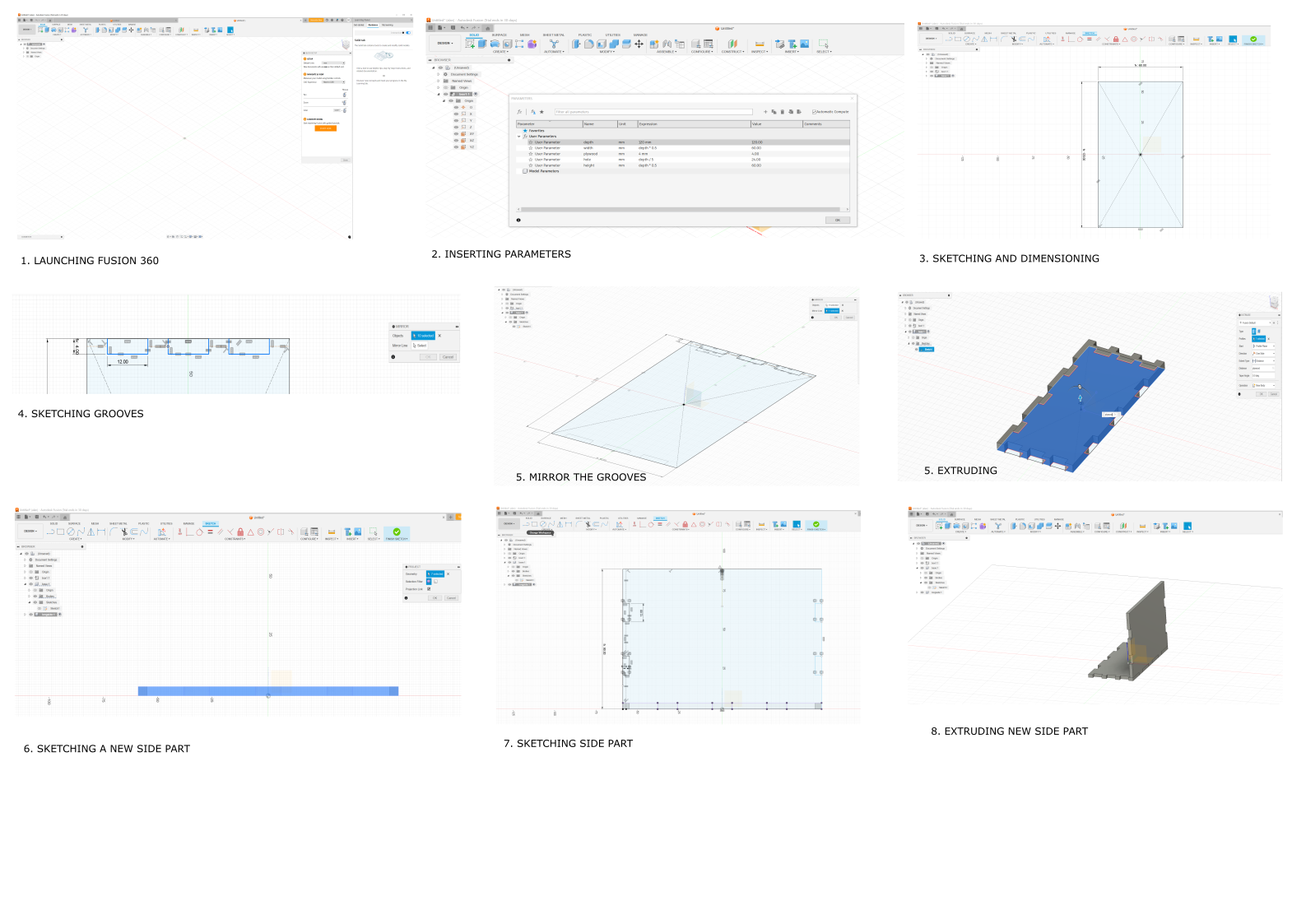
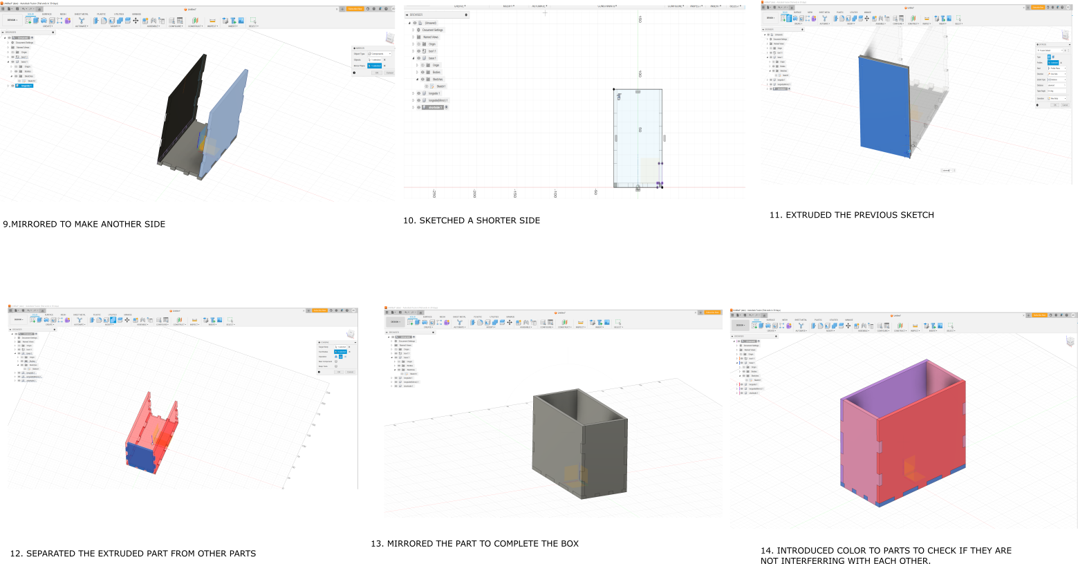
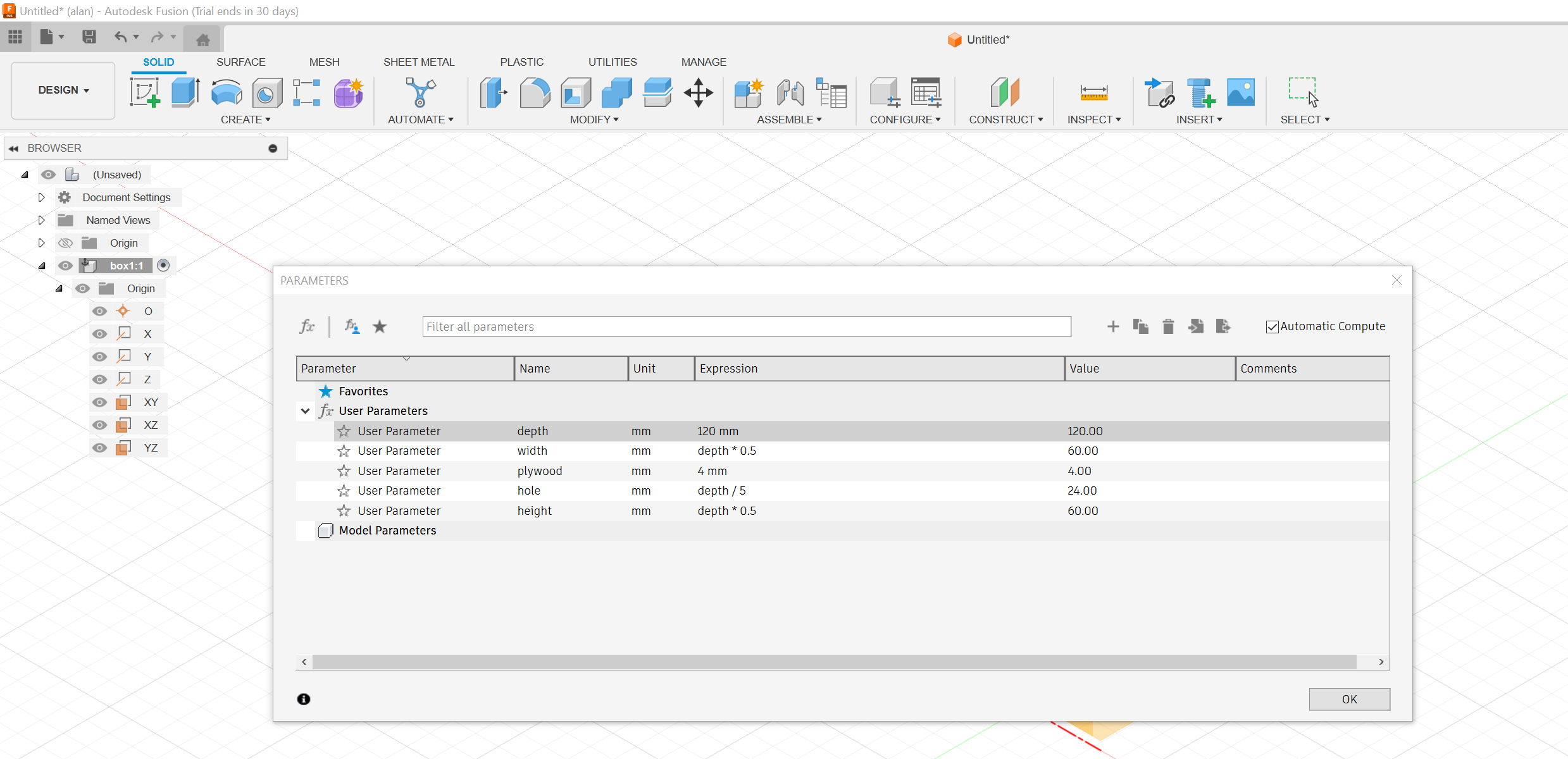
The design was started off by setting up parameters, to enable the ability to edit the sizes of the design without having to start afresh.
After drawing the parts I saved the files as DXF FILES to be able to cut them with the laser cutter.
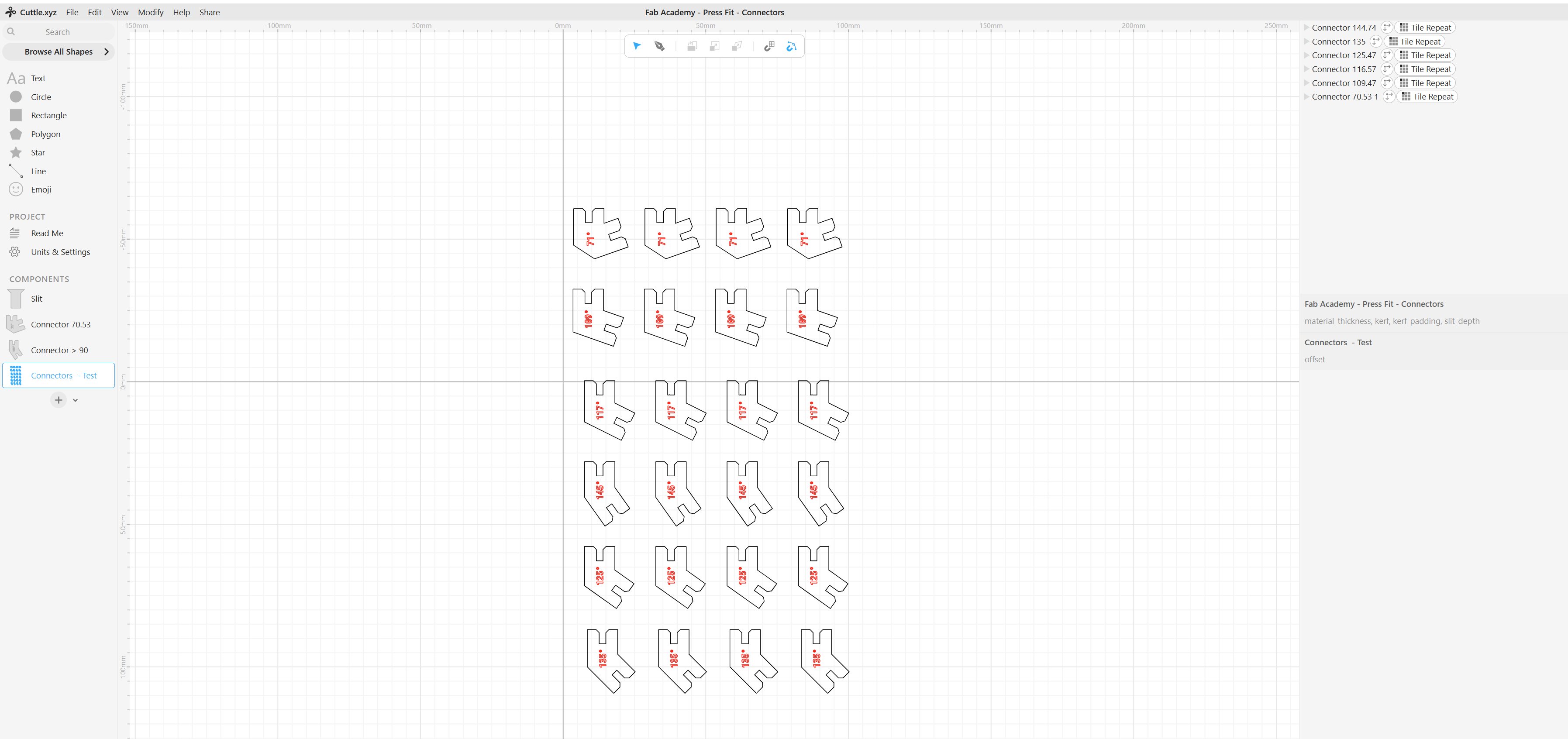
DESIGNING PARAMETRIC MODEL WITH CUDDLE.XYZ
Came across the cuddle tool on one of the previous students, Nadieh which got my attention. I opted to try use it for designing another parametric model.
I then watched some youtube videos to see how the tools is used.
GETTING STARTED WITH CUTTLE.XYZ
I launched the software here, and signed up.
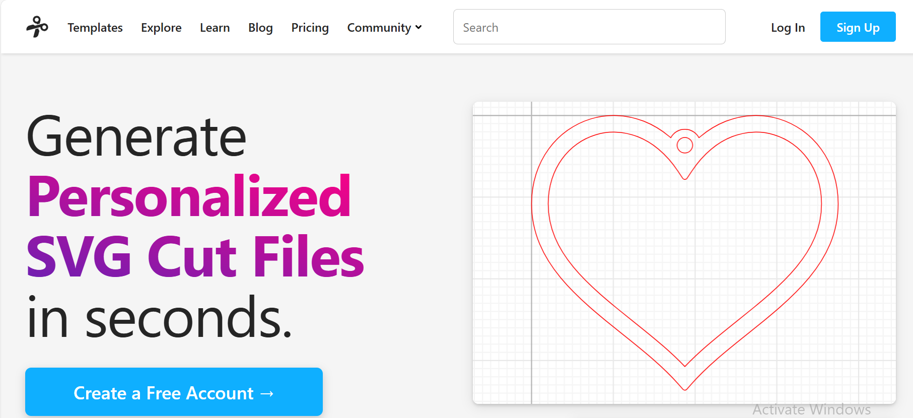
I then opened a new project to start working on the software.
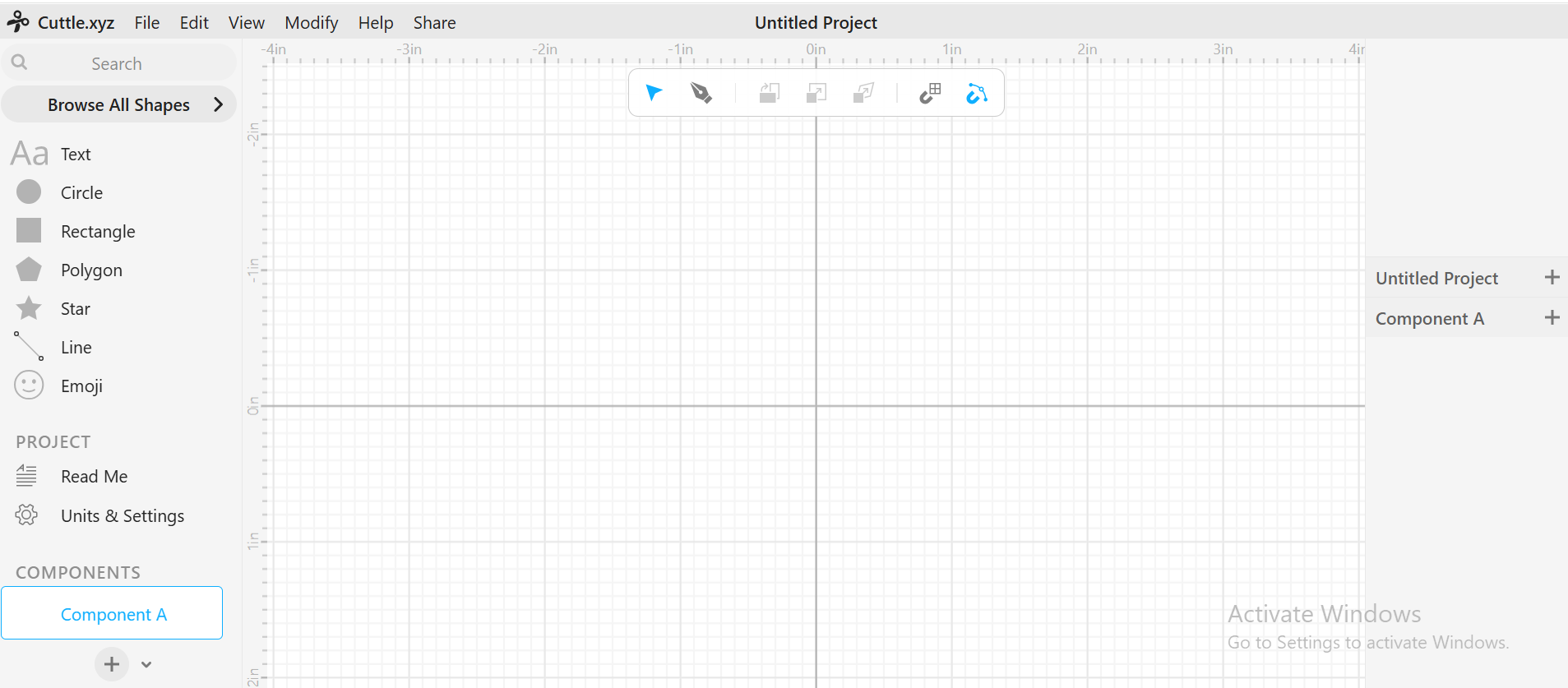
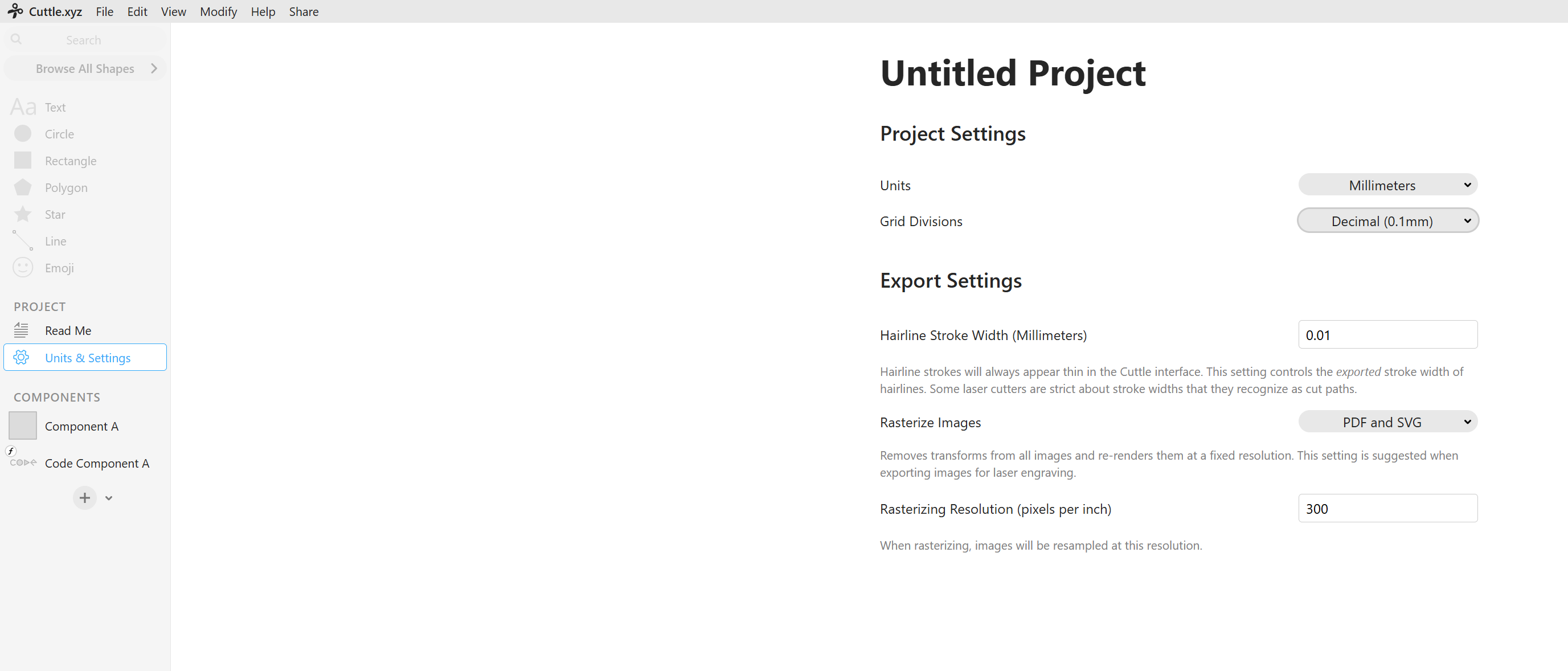
I then set the project settings, changing the units to mm.
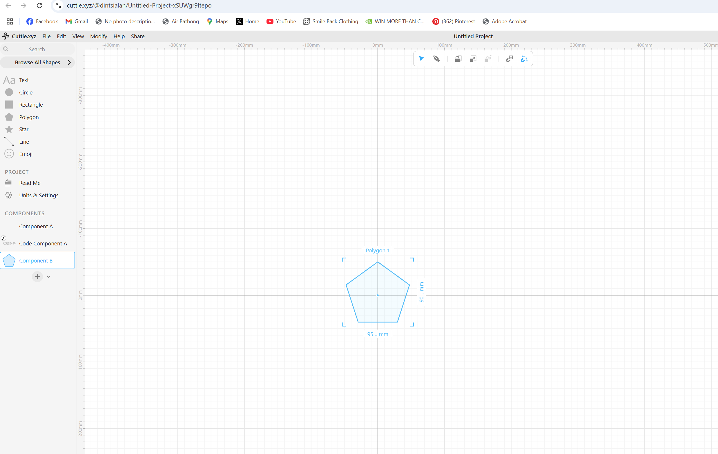
I started sketching, of which I imported the pentagon in the workspace.
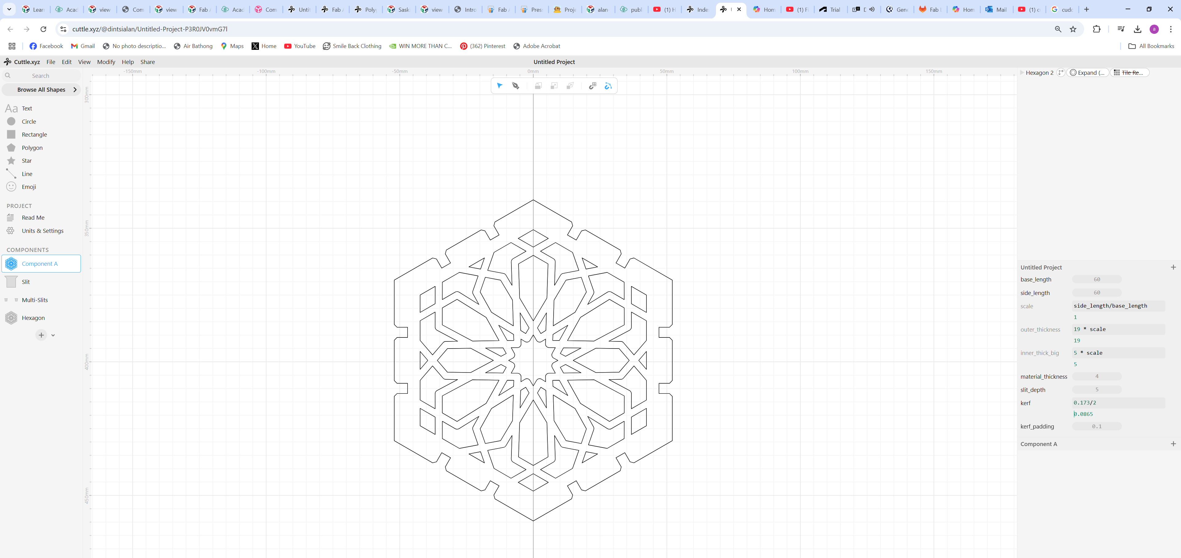
Because of time constraints I opted to download Nadieh's files and modified them, changing sizes.
LASER CUTTING PARAMETRIC MODELS
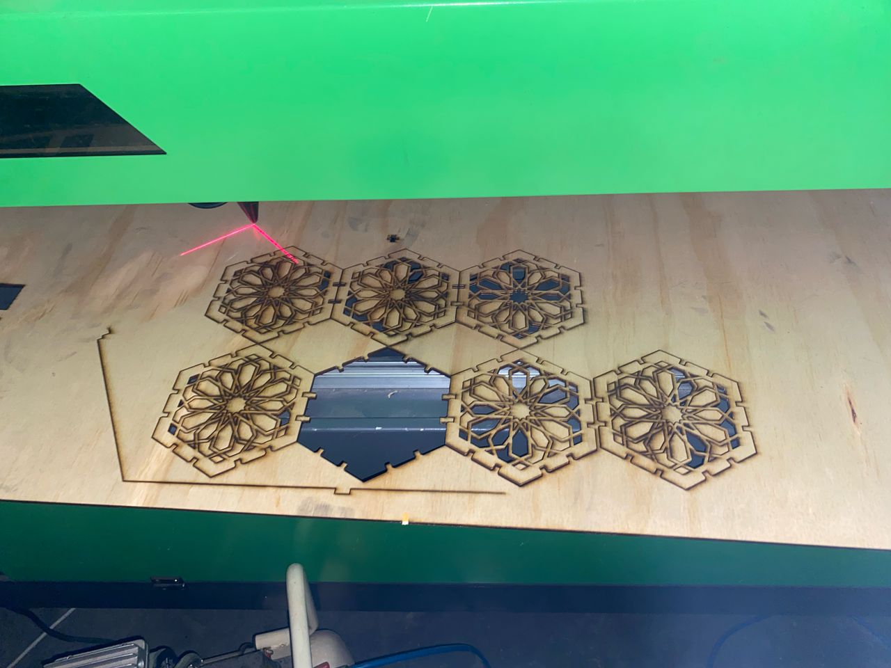
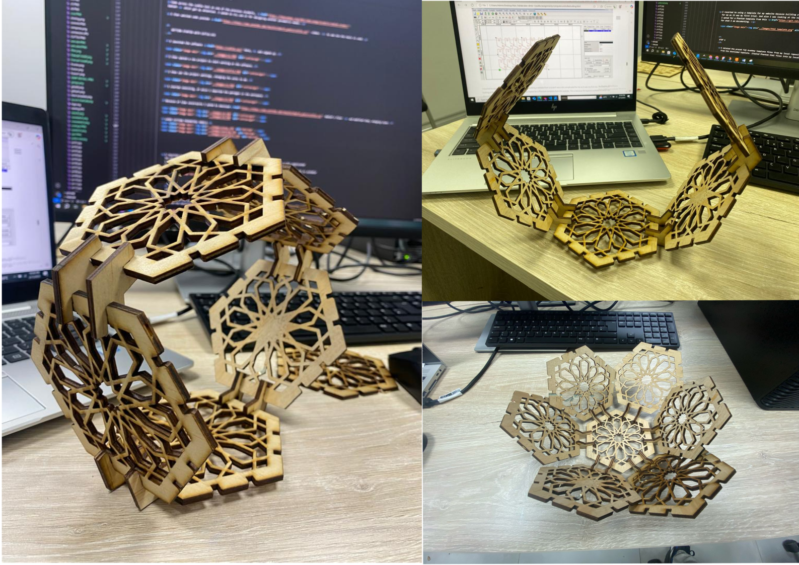
The files where then changed to dxf file and then imported into RDworks, a software that is used to operate our CO2 laser cutter. The parts where then nested as shown in the pictures.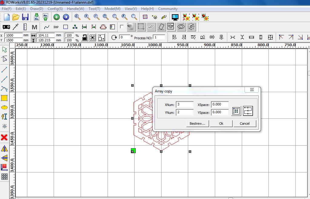
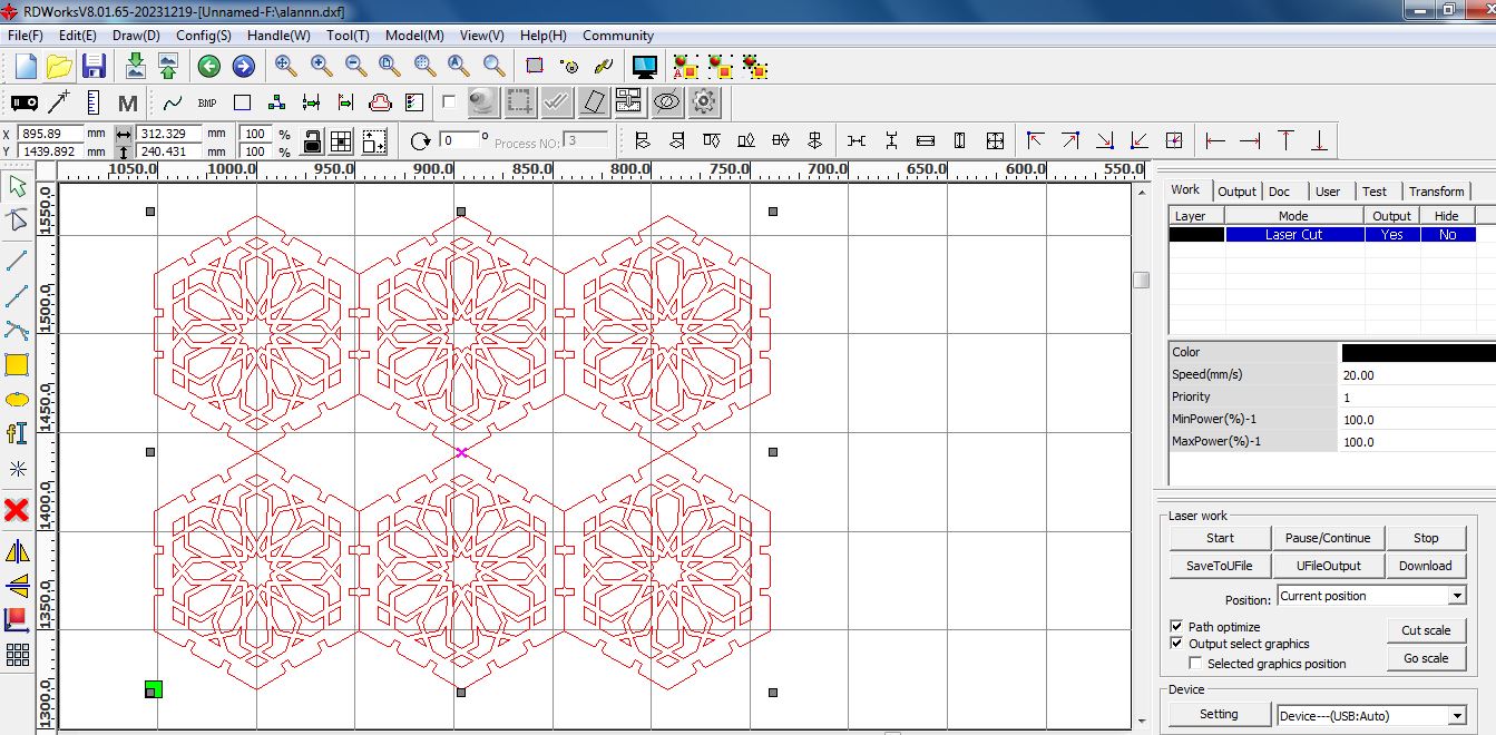
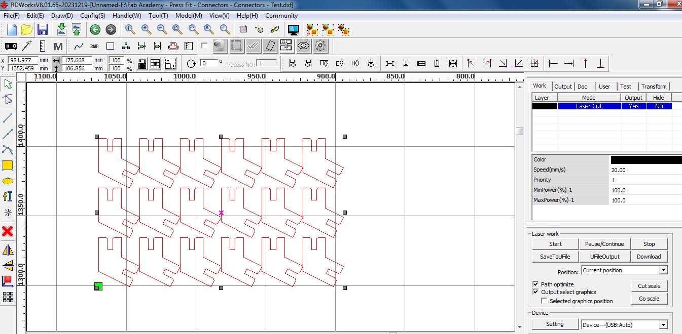
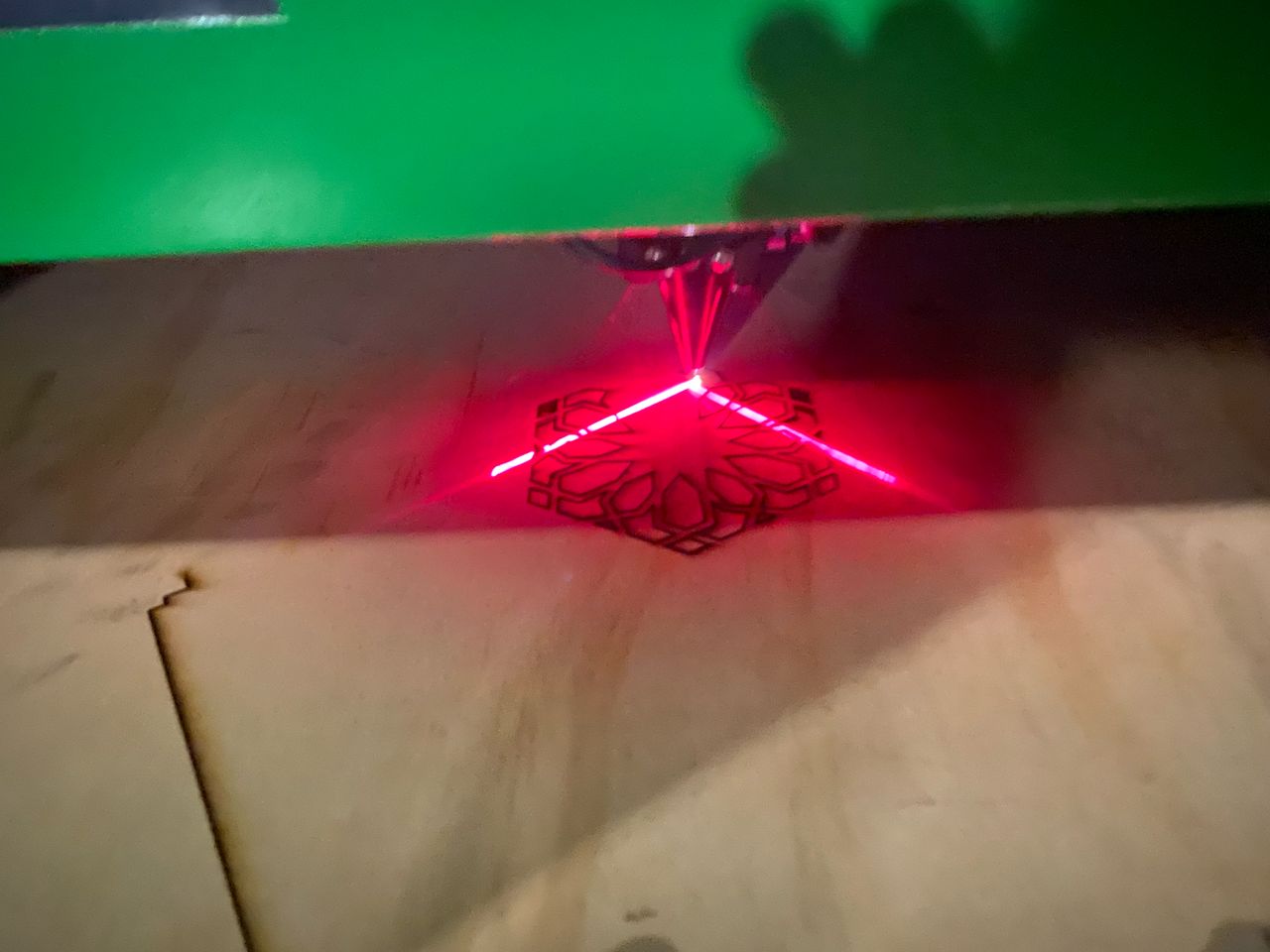
The files were then cut using a CO2 laser cutter as shown below, at a power of 100 and with speed at 20. The material used is 4mm plywood.
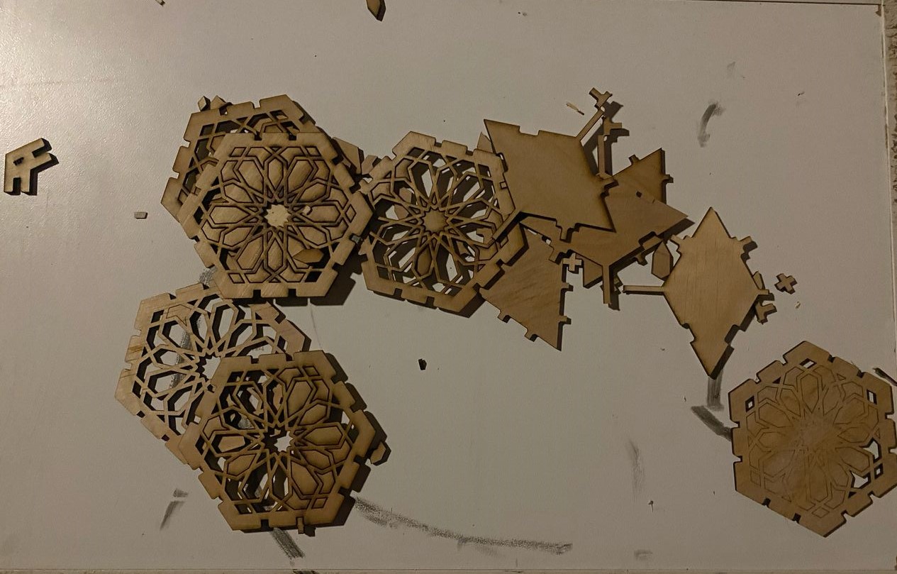
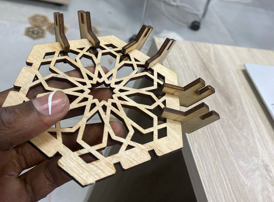
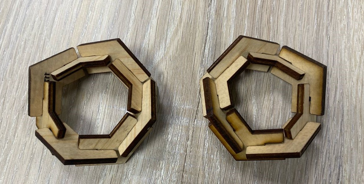
I introduced the connector after cutting to start assembly the parts I have made.The parts were not tightly fitting(were A bit loose) and also they were a bit longer, so I decided to continue with them. the following pictures are the different constructions of my parametric design. And also I had to use force to push out the unwanted cut parts, this is because the laser did not completely cut the material.
VINYL CUTTING
STEP 1
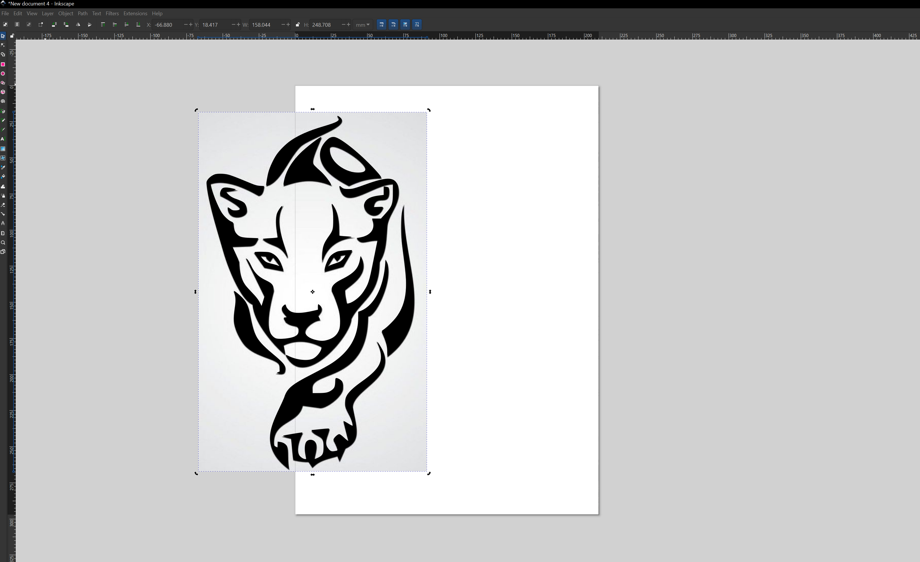
For my vinyl cutting design I downloaded the pictures from Pinterest and then imported them into Inkscape software.
STEP 2
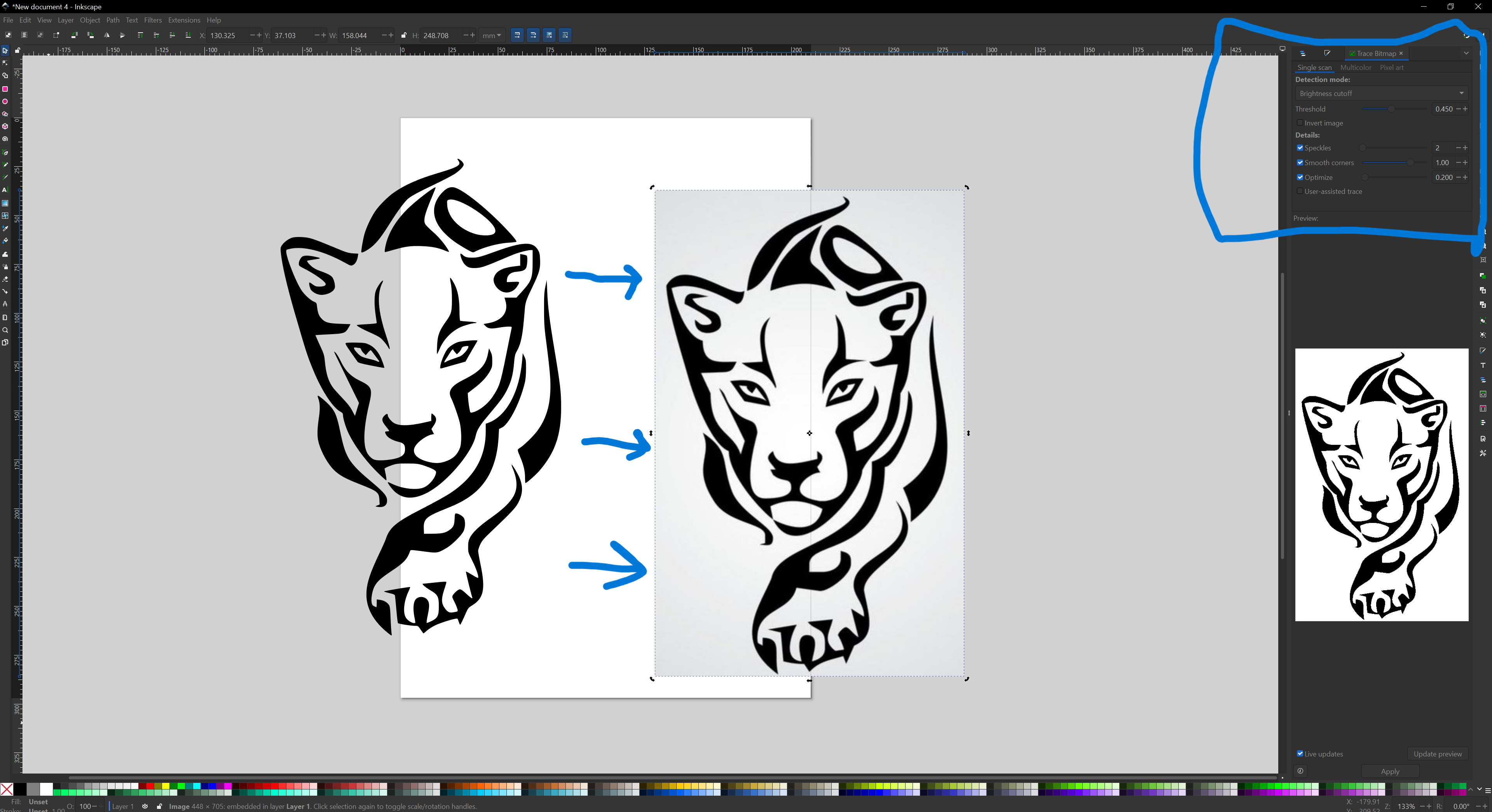
I then clicked trace the bitmap to extract the outlines of the images to be able to save it as a dxf file. After tracing I deleted the image and left with the outlines.
STEP 3
I then launched the CutStudio software and then imported the save files from Inkscape into it. Cutstudio is the software used to operate the vinyl cutter.The vinyl cutter used is the Roland CAMM1-Servo.
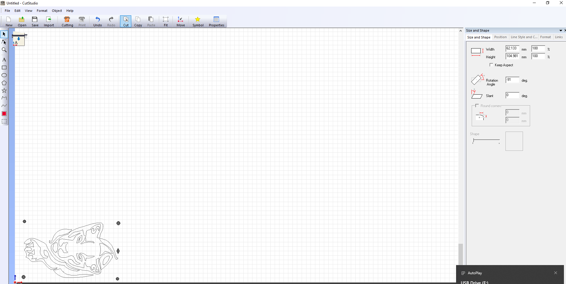
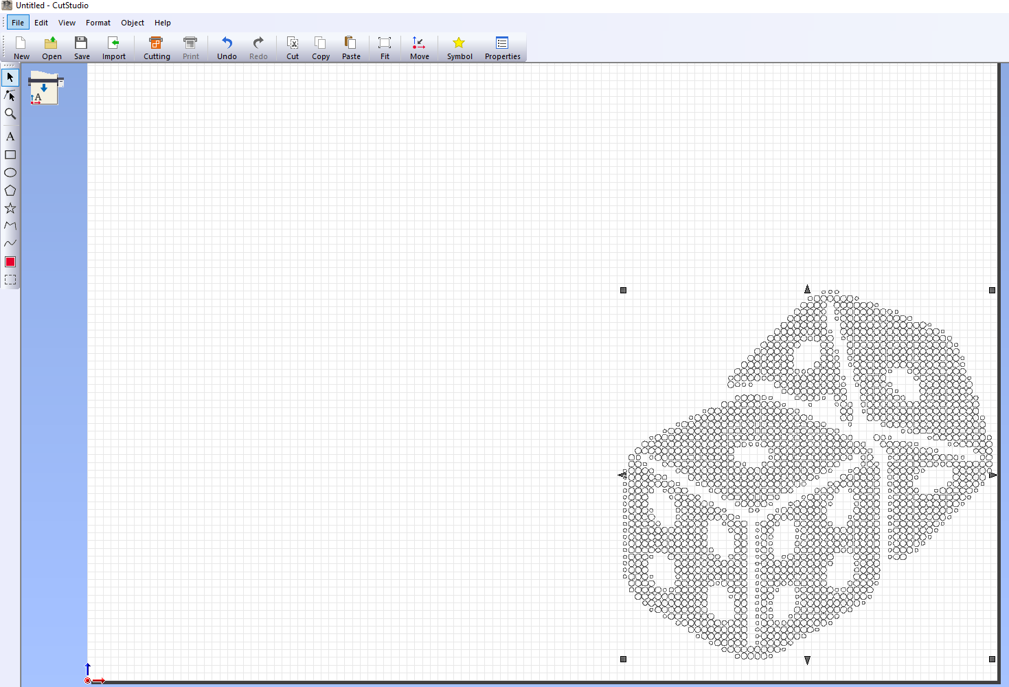
STEP 4
I then switched on the machine and set the parameters for cutting the vinyl, of which speed was 20cm/s and force at 50gf and then loaded the material.
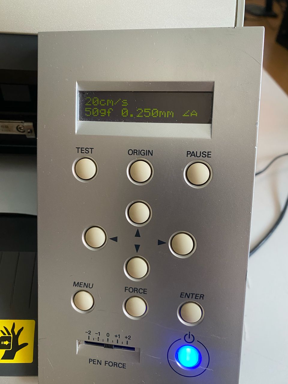
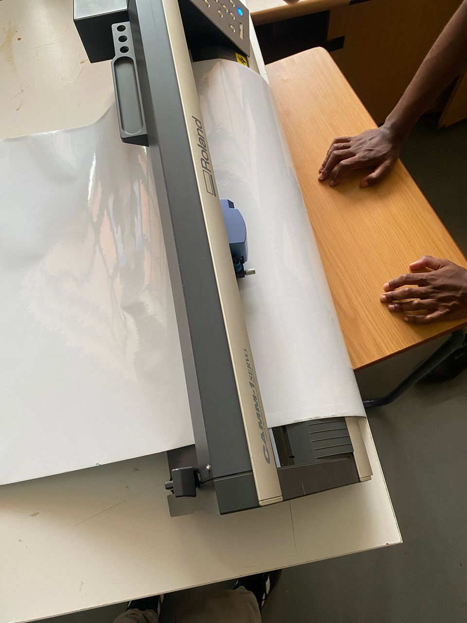
STEP 5
I then started cutting the vinyl.
STEP 6
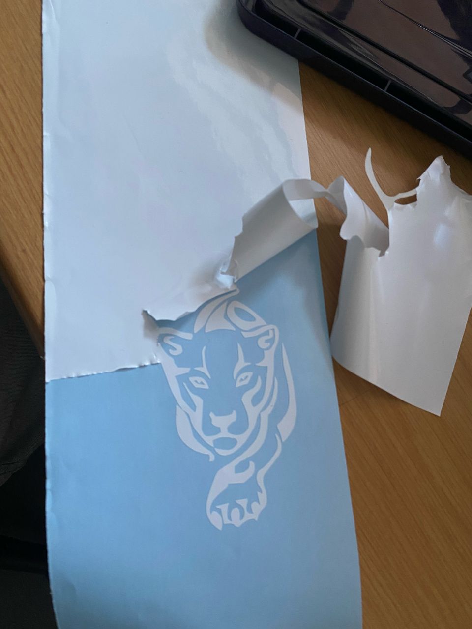
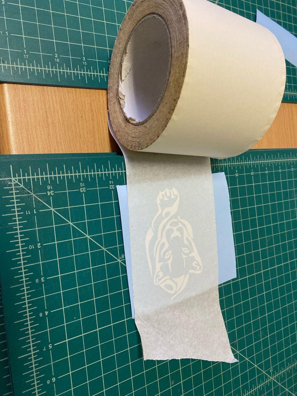
After cutting I then started weeding,(removing unwanted material) from the cut vinyl and applied transferring tape to it prepairing it for pasting it.
WEEDING
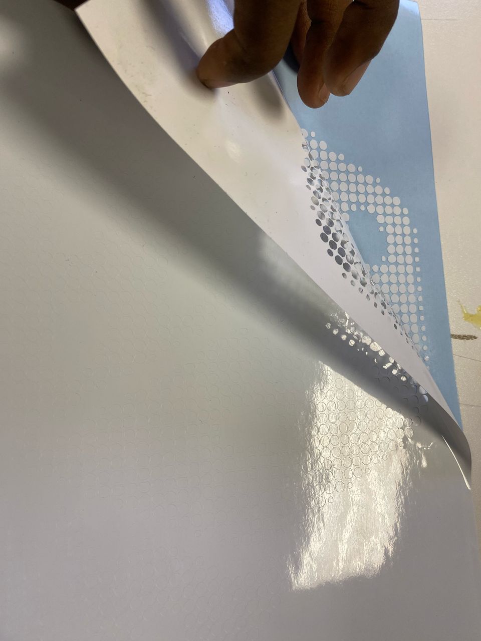
TRANFERRING THE VINYL
PASTING
I then transferred the cut vinyls in my laptops.
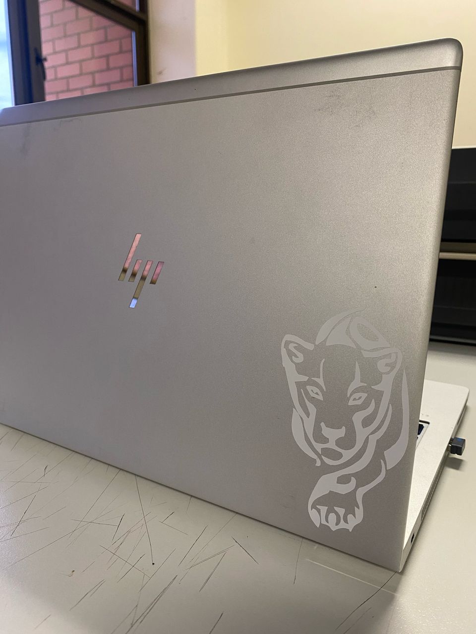
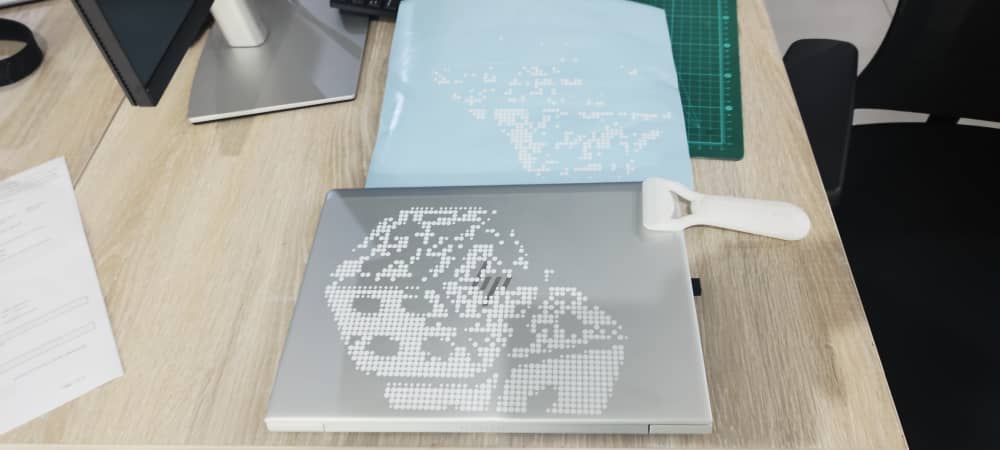
The vinyl pasted on the second laptop did not come out nicely as some of the vinyl did not stick to the laptop. This is because I reoved the masking tape quickly or the problem was with the masking tape as it did not stick properly.
FILES