SYSTEM INTEGRATION
MECHANICAL DESIGN OF THE SYSTEM
System diagram
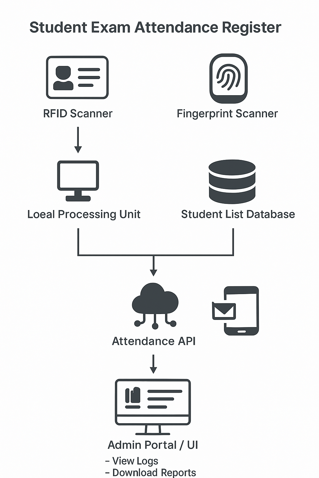
My system is composed of a circuit enclosure/case which is shown below. It has two sides, which is the back and front. This are will be used to cover or protected the electronic components as well as provide project aesthetics.
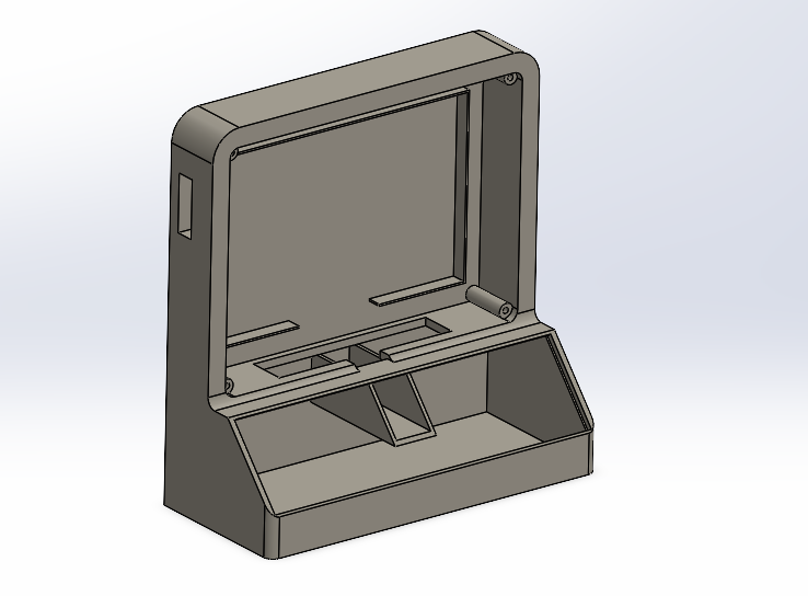
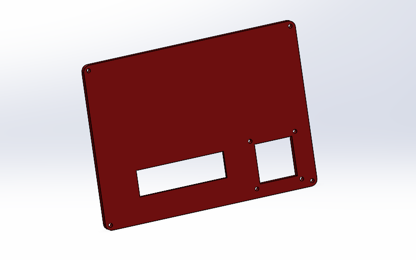
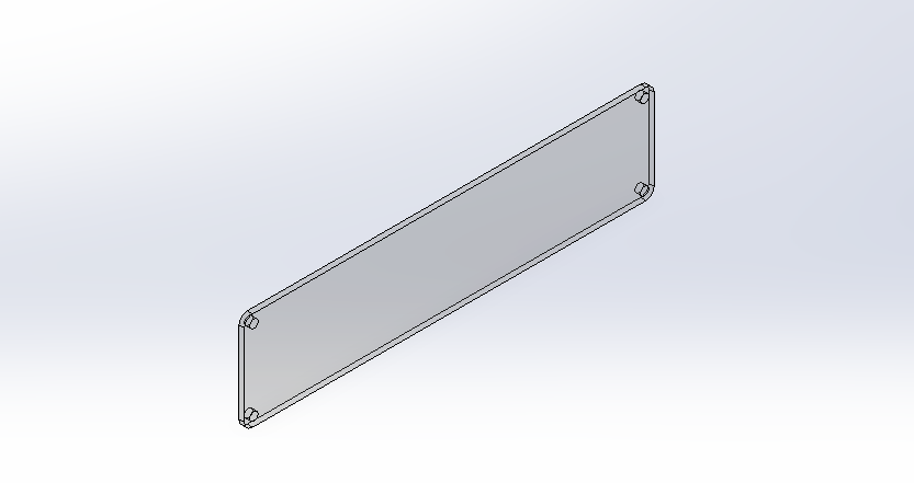
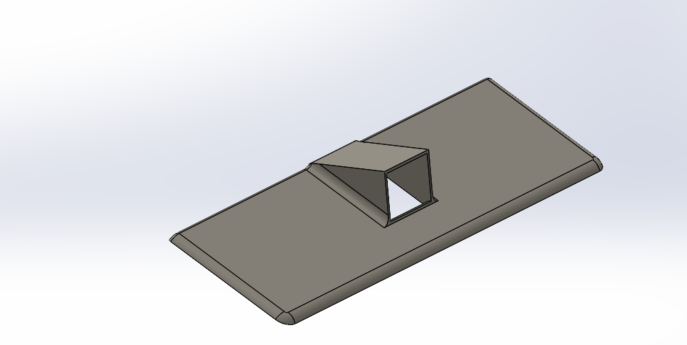
The following is the full assembly of the project casing, of which some parts will be joined by screws.
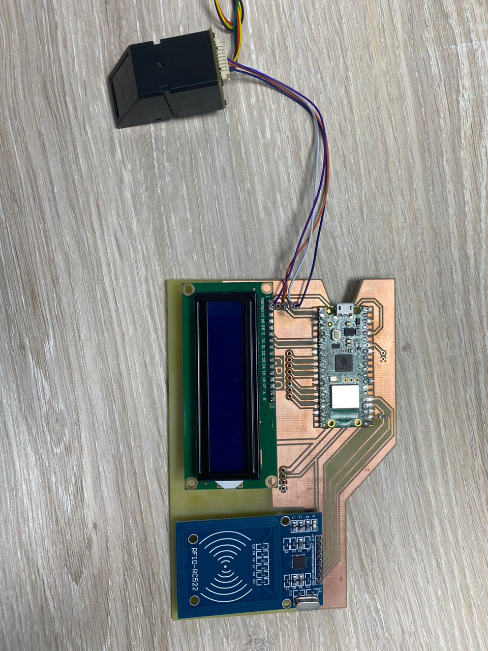
ELECTRONIC COMPONENTS USED
The following are components to use for my project.
- OLED DISPLAY
- RFID-RC522
- FINGER PRINT SCANNER
- RASPBERRY PI PICO W
- BUZZER
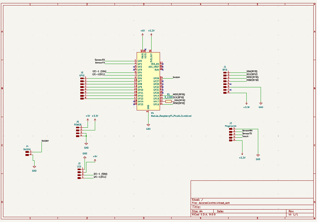
ELECTRONIC CIRCUIT DESIGN
The design for the circuit and the board has been made.
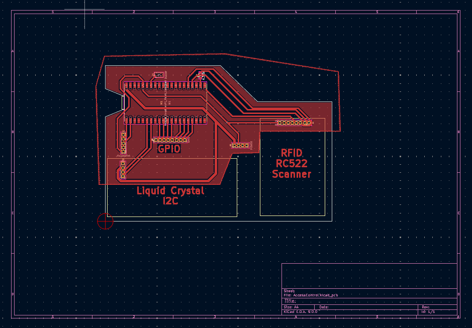
PCB DESIGN
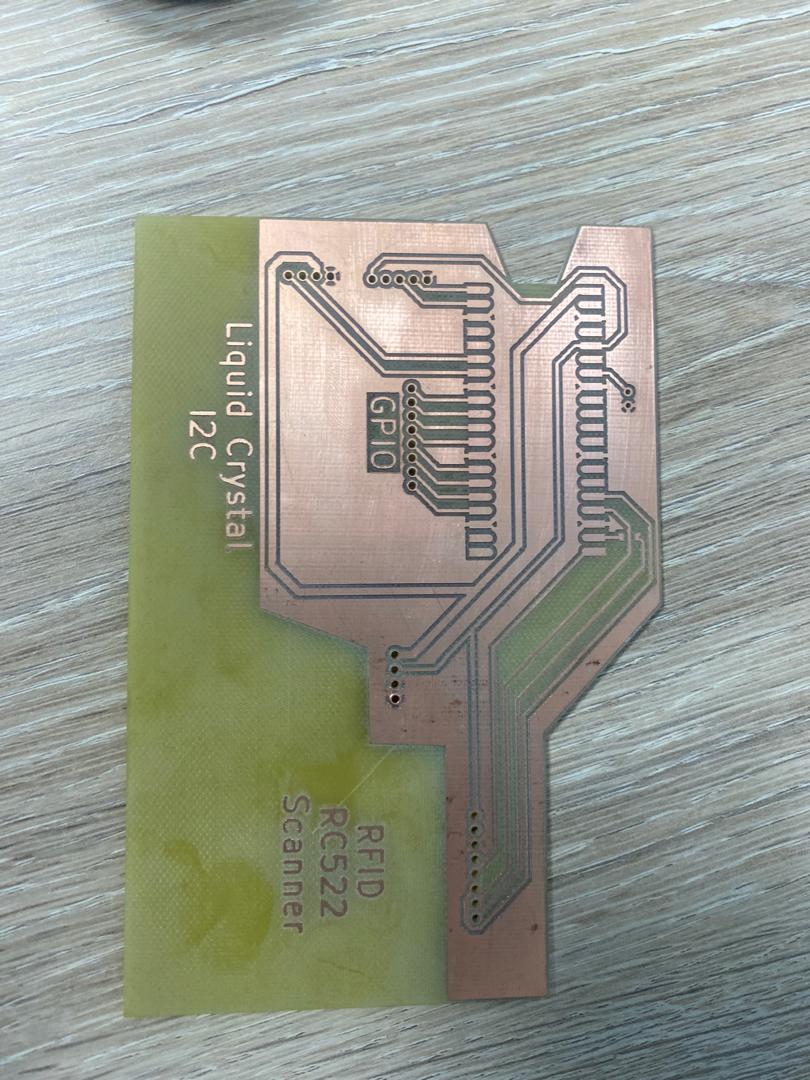
PCB PRODUCTION
The designed circuit board was then milled.
And then soldered
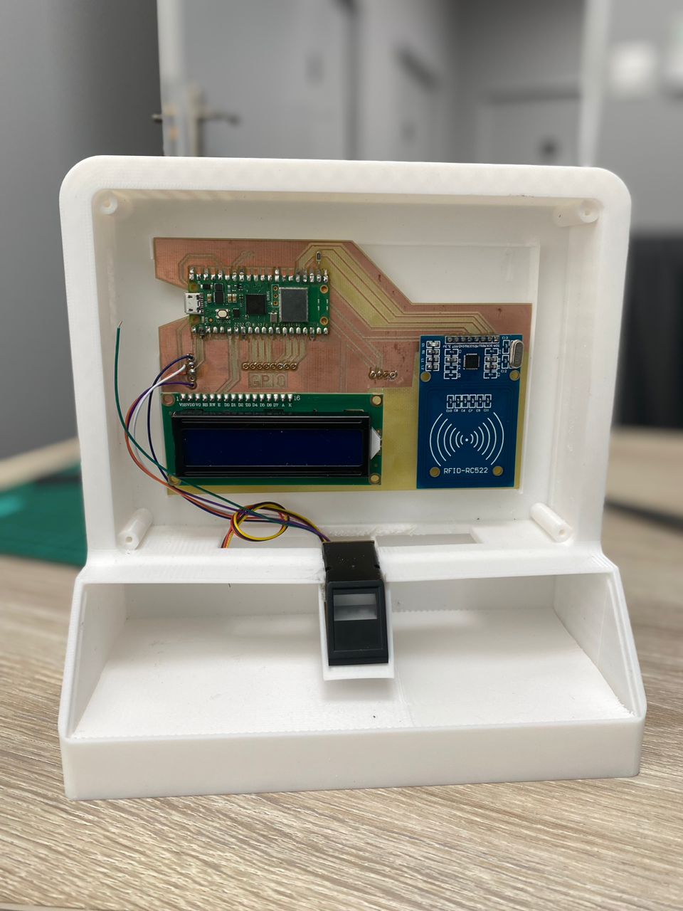
ASSEMBLY
The PCB and the product components were mounted to the casing as shown. I made some holders where the pcb can be placed/slotted then reinforced it with hot air gun.
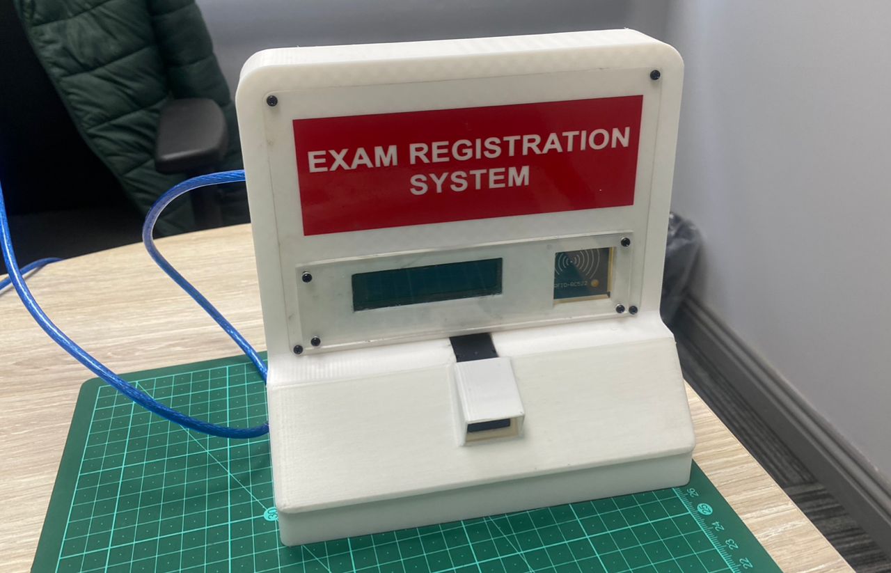
THE FINAL ASSEMBLED PRODUCT
FILES