COMPUTER AIDED DESIGN

Computer-aided design(CAD) is the use of computers to aid in the creation, modification, analysis or optimization of a design. It is used to increase the productivity of the designer, improve quality of design, improve communications through documentation and database for manufacturing. Designs through CAD software help protect products and inventions when used in patent applications. CAD software for mechanical design uses either vector-based graphics to depict the objects of traditional drafting, or may also produce raster graphics showing the overall appearance of designed objects. CAD may be used to design curves and figures in 2D space; or curves, surfaces and solid in 3D space.
TYPES OF CAD
2-DIMENSIONAL
2D CAD uses fundamental geometric shapes like lines, rectangles, arcs, and circles to make flat drawings. 2D CAD software also annotates drawings using text, dimensions, leaders, and tables. This type of CAD is used to design, plan, section, and detail structures and represent elevation views in the built environment. Additionally, the drawings convey how various components work together to form assemblies and offer insight into potential locations that may require additional inspection.3-DIMENSIONAL
3D CAD has grown in popularity as a design tool as computer processing power and graphic display capabilities have improved. In general, 3D CAD software produces a realistic model of an object, enabling designers to address potential issues earlier in the product lifecycle. Like most software, CAD tools may be better for different modeling applications. The three main categories of CAD software modeling are: Solid Modeling: A solid model is a 3D image that represents the volume of an object and provides a complete and accurate representation of its geometry. Wireframe Modeling: A wireframe model uses lines and curves to represent the edges of an object – essentially, a skeletal view without surface details. Surface Modeling: A surface model represents complex surfaces by defining the exterior shape of an object. Designers frequently use this model type for intricate and detailed designs.
2D DESIGN TOOLS
STRATEGIES FOR GEOMETRIC MODELLING IN 2D
VECTOR VS BITMAP
VECTOR GRAPHICS
Vector graphics are resolution independent. They are based on mathematical expressions and use points, lines, curves and polygons to represent images. Because they use mathmatical formulas, they can be resized, bent and stretched without losing resolution. Lines remain crisp and sharp when the size of the drawing is increased.
BITMAP / PIXELMAP / RASTER GRAPHICS
Pixels (or "picture elements") are the smallest controllable unit of a digital image.Bitmap / pixel map images are made up a rectangular grid of pixels.
Bitmapimages are comprised of mapped bits. This means that the image information is stored as a series of values that are either zeros or ones. This gives a computer a way to store a binary image made up of black and white pixels
The term "raster" is used to describe both bitmaps and pixelmaps and indicates that these graphics are resoultion dependent. If you resize a raster graphic to a larger size, the square pixels will become apparent.
TRYING OUT 2D SOFTWARES
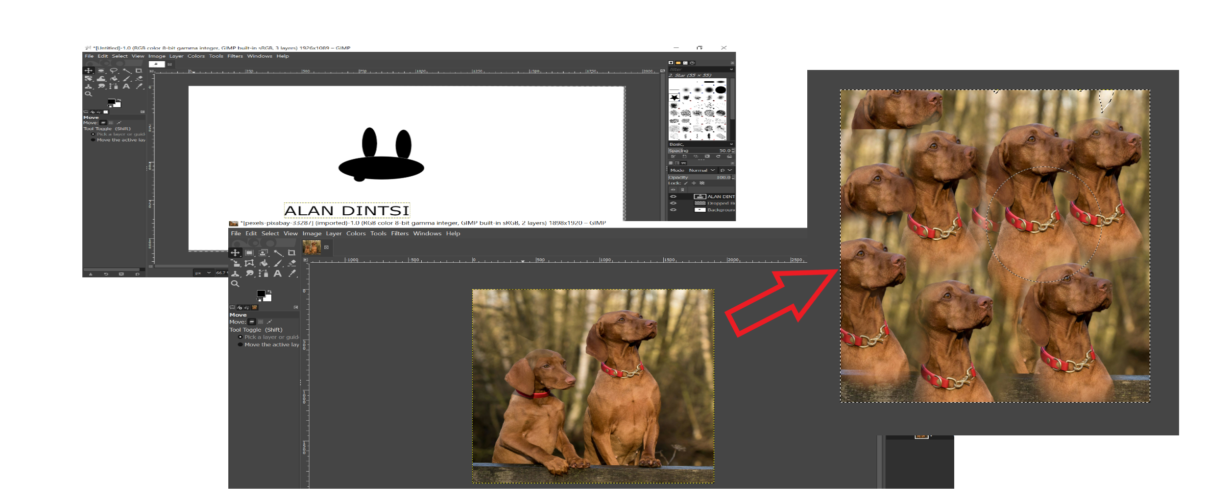
GIMP
I downloaded and installed GIMP SOFTWARE. I started working on to
familiarise myself with its tools and how to use use. I also watched the
youtube videos to get a better understanding on how to use the software.
INKSCAPE
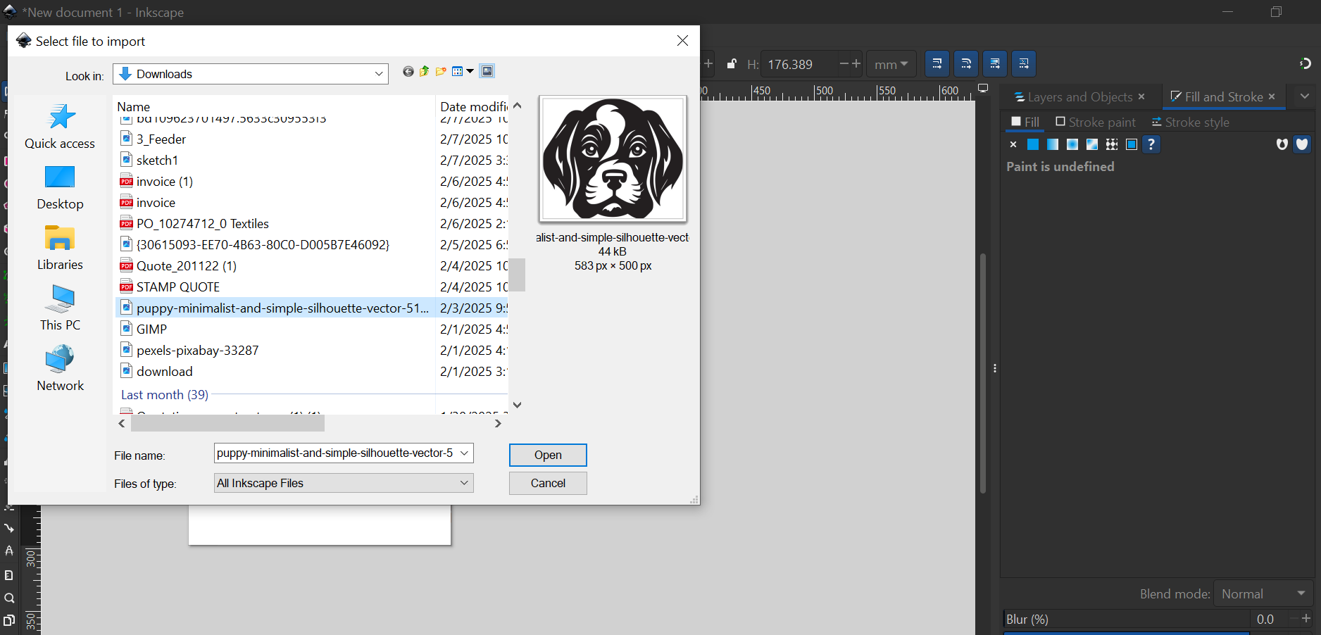
I downloaded and installed Inkscape software, then followed a tutorial to try and make a logo for my proposed final project.
GETTING STARTED WITH INKSCAPE
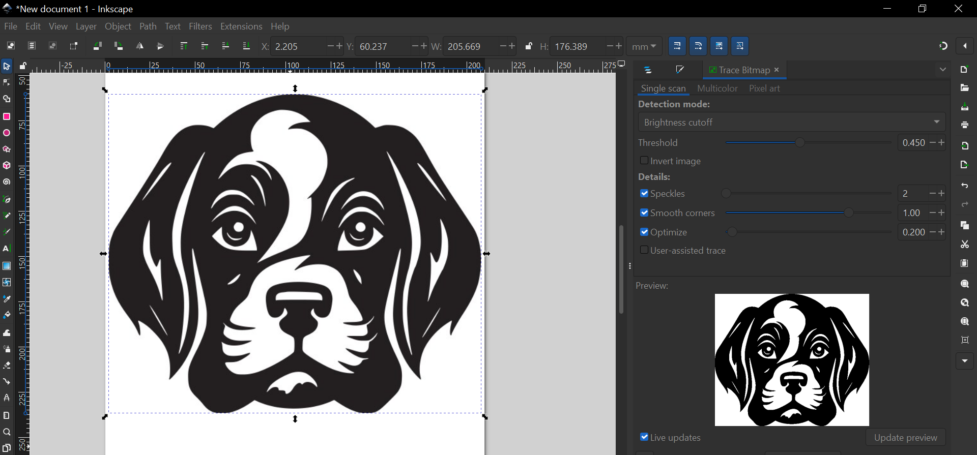
I downloaded a raster image from the internet and imported it on Inkscape.
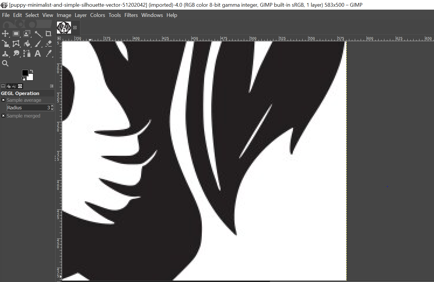
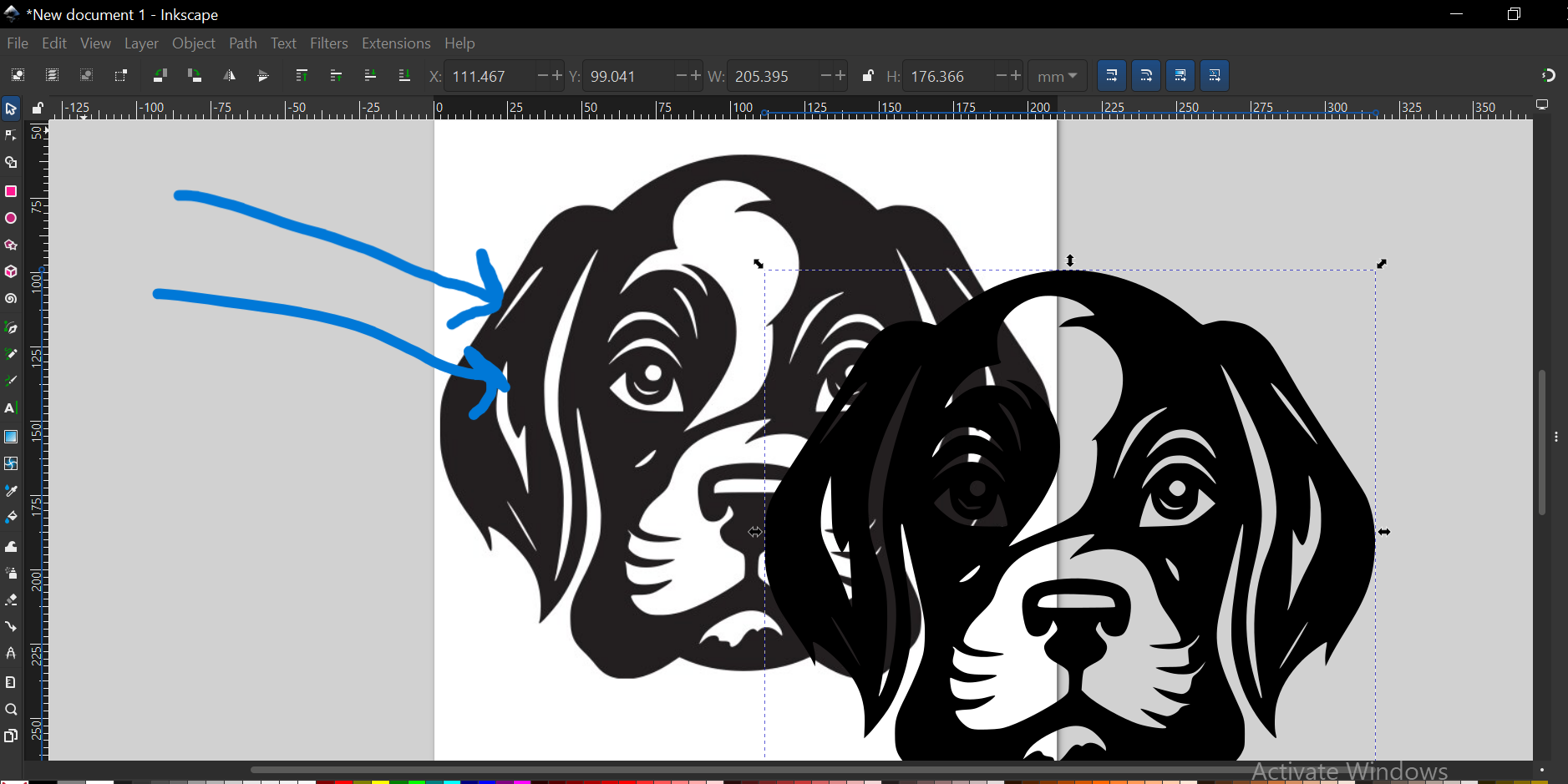
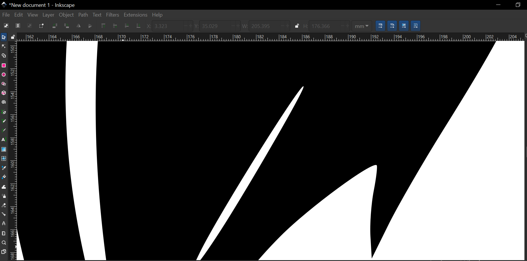
I have zoomed to show that as you zoom the raster image it pixelates.
I then went to path then traced the image to make a vector image then deleted the original image(the one with arrows).
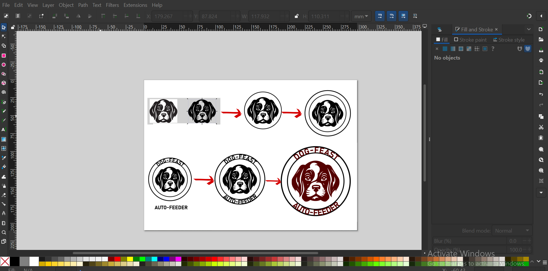
I zoomed to check if indeed the image is now vectorized, after that I then started working on the Logo as shown by the process image.
The following is the process I took to come up with a logo, as a way of trying the Inkscape tutorial.
The final file in .SVG format can be downloaded here
3D DESIGN TOOLS
SOLIDWORKS
SolidWorks (stylized as SOLIDWORKS) is a brand within Dassault Systèmes that develops and markets software for solid modeling computer-aided design (CAD), computer-aided engineering (CAE), 3D CAD design, collaboration, analysis, and product data management.
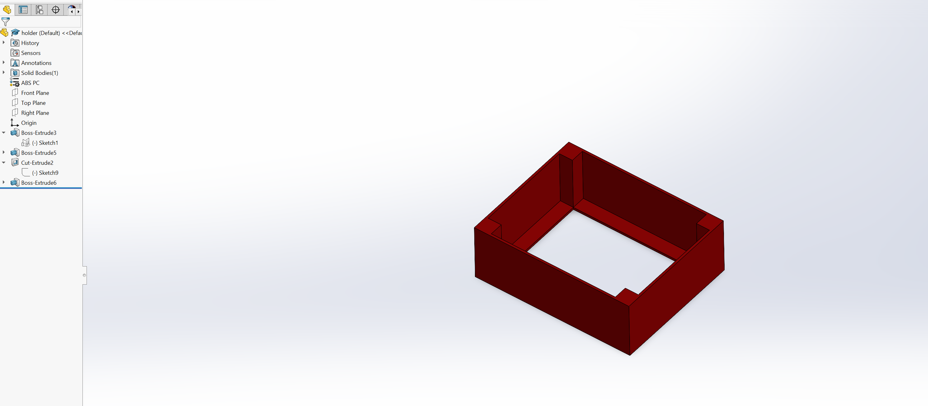
CREATING A MODEL WITH SOLIDWORKS
I started by drawing a rectangle with a rectangle tool and dimensioned it, then offset it.
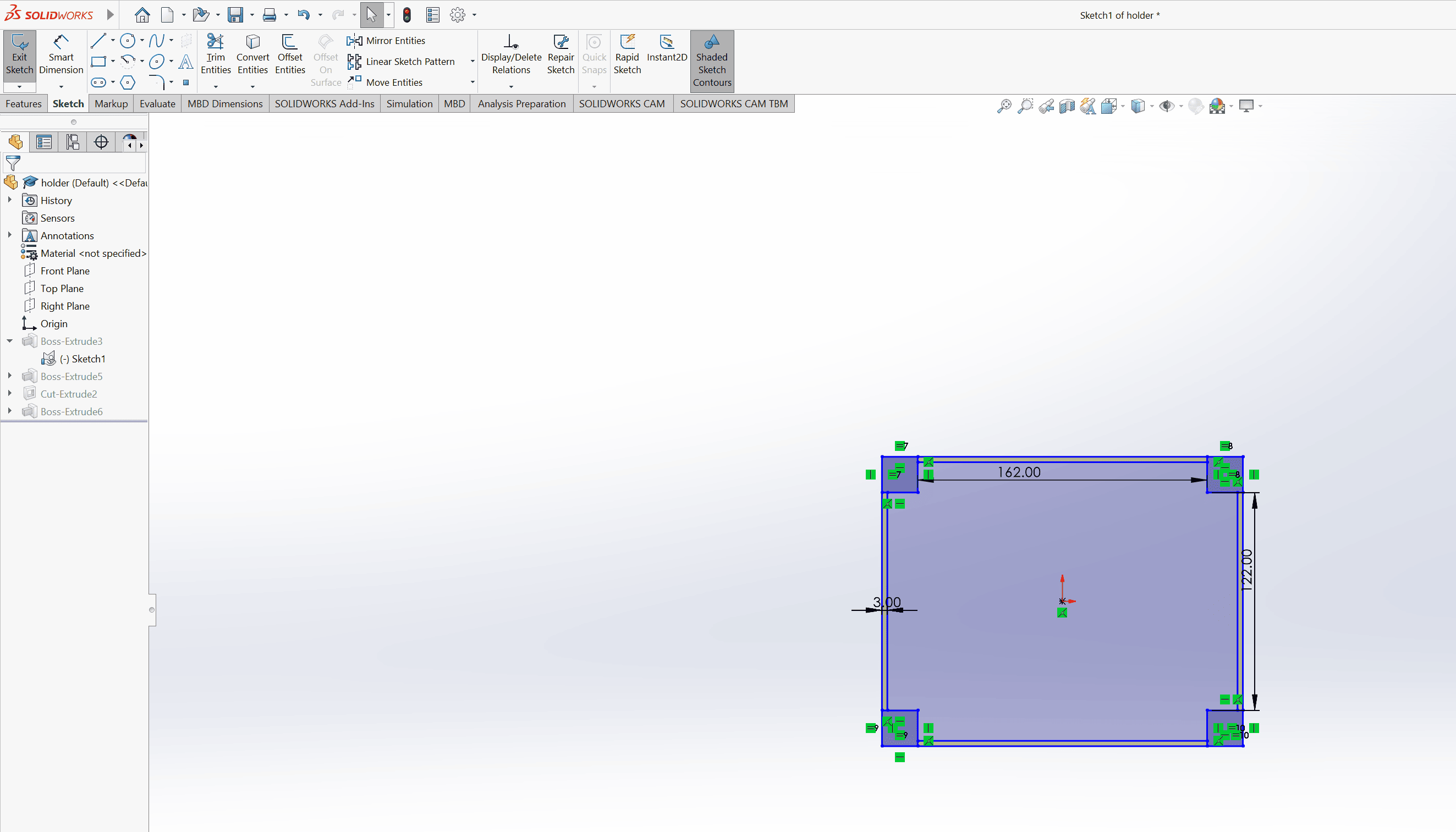
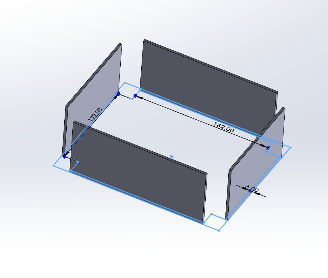
I extruded the sketch to make a solid model.
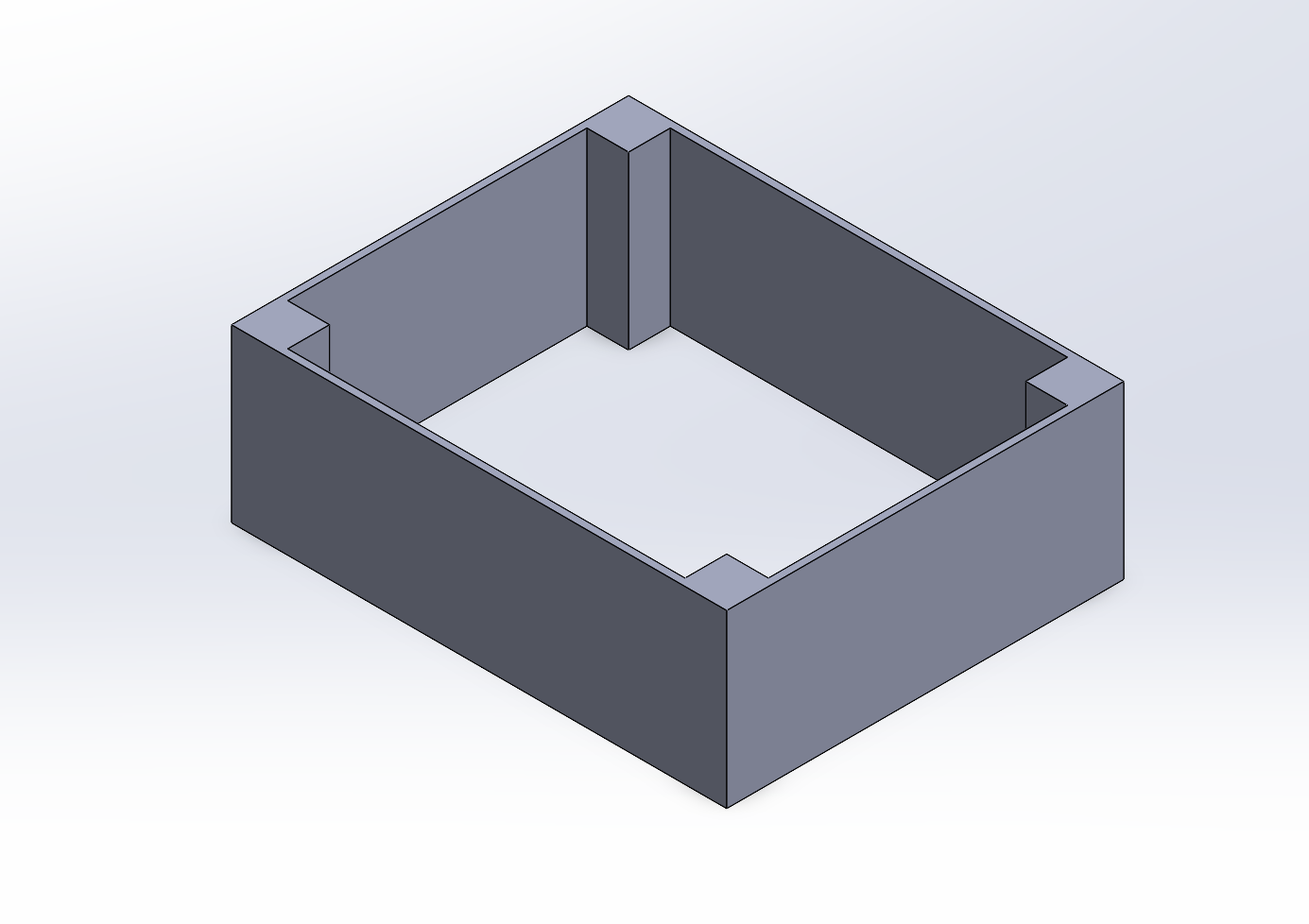
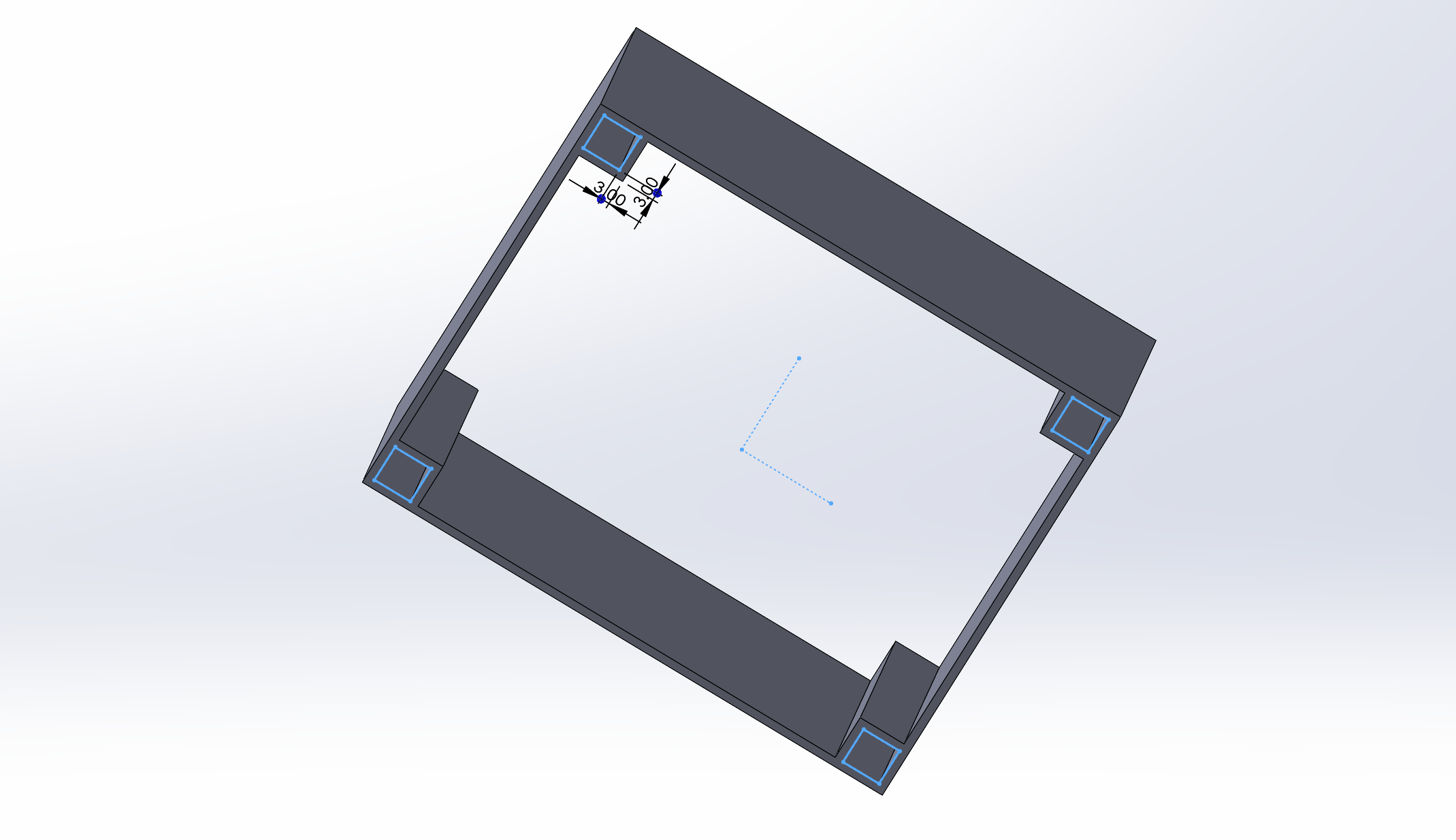
I sketched and extude cut the squares in the model which will as slots for holding the legs of my product.
I introduced a section that will hold a hopper and then assigned the material to the model.
ONSHAPE
Onshape is a cloud-based computer-aided design (CAD) program that allows teams to collaborate on product design in real time. It's a software as a service (SaaS) system that's accessible via a web browser or mobile app. How it works: Onshape is delivered over the internet, so users can access it from any device with an internet connection Onshape upgrades are released directly to the web interface, so users don't need to maintain the software Onshape stores data in a database on cloud servers
TRYING OUT ONSHAPE FOR THE FIRST TIME
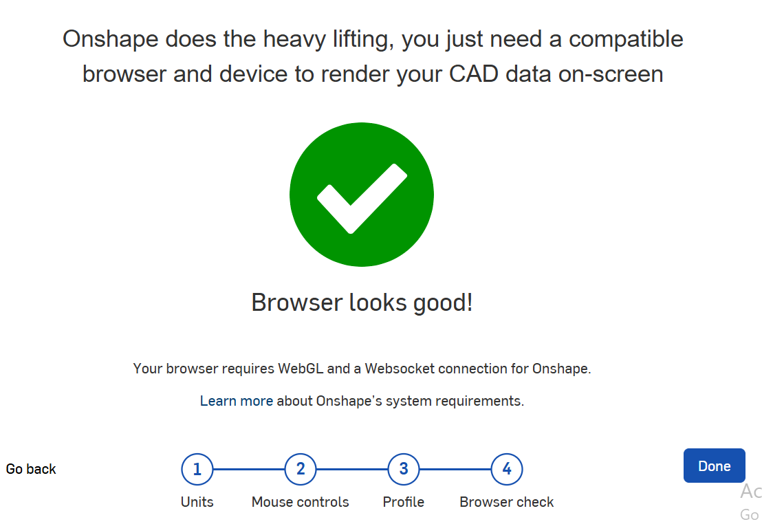
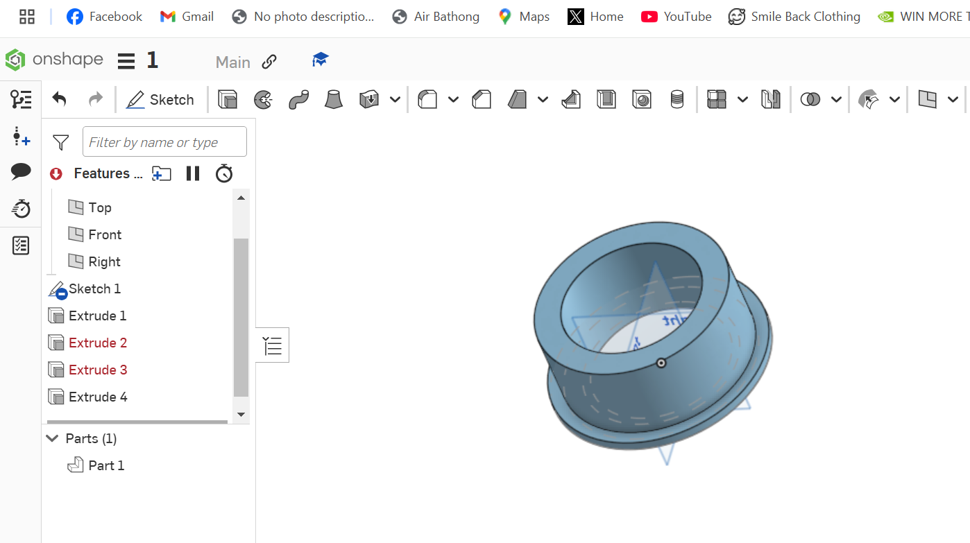
Started off by lauching the onshape software then set up the parameters.
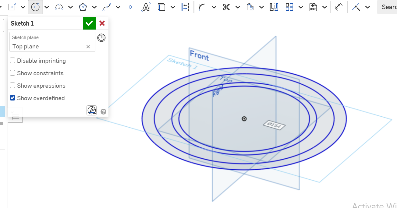
Opened a new document and sketched basic shapes.
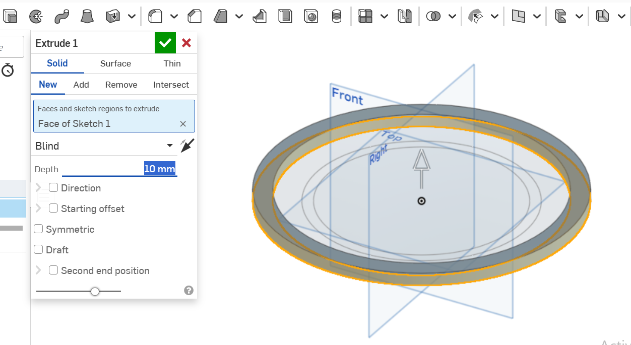
The I tried other features, of which in this case I captured the extrude feature.
FREECAD
FreeCAD is a general-purpose parametric 3D computer-aided design (CAD) modeler and a building information modeling (BIM) software application with finite element method (FEM) support. It is intended for mechanical engineering product design but also expands to a wider range of uses around engineering, such as architecture or electrical engineering.FreeCAD is free and open-source, under the LGPL-2.0-or-later license, and available for Linux, macOS, and Windows operating systems. Users can extend the functionality of the software using the Python programming language.
TRYING OUT FREECAD FOR THE FIRST TIME
I downloaded and installed FreeCad software, then watched this tutorial to learn how to get started with the software.
I then launched the software and started working on a possible part for my final project as a way of trying to familiarize myself with the software. The following steps were folowed to come up with a part for my final product.
LAUNCHING
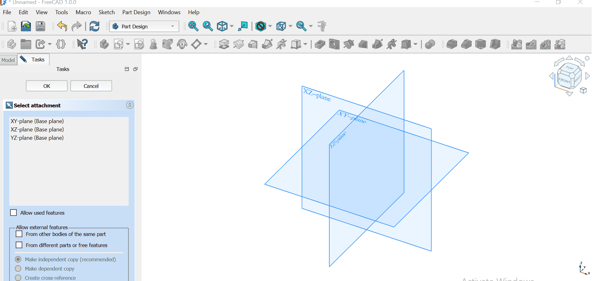
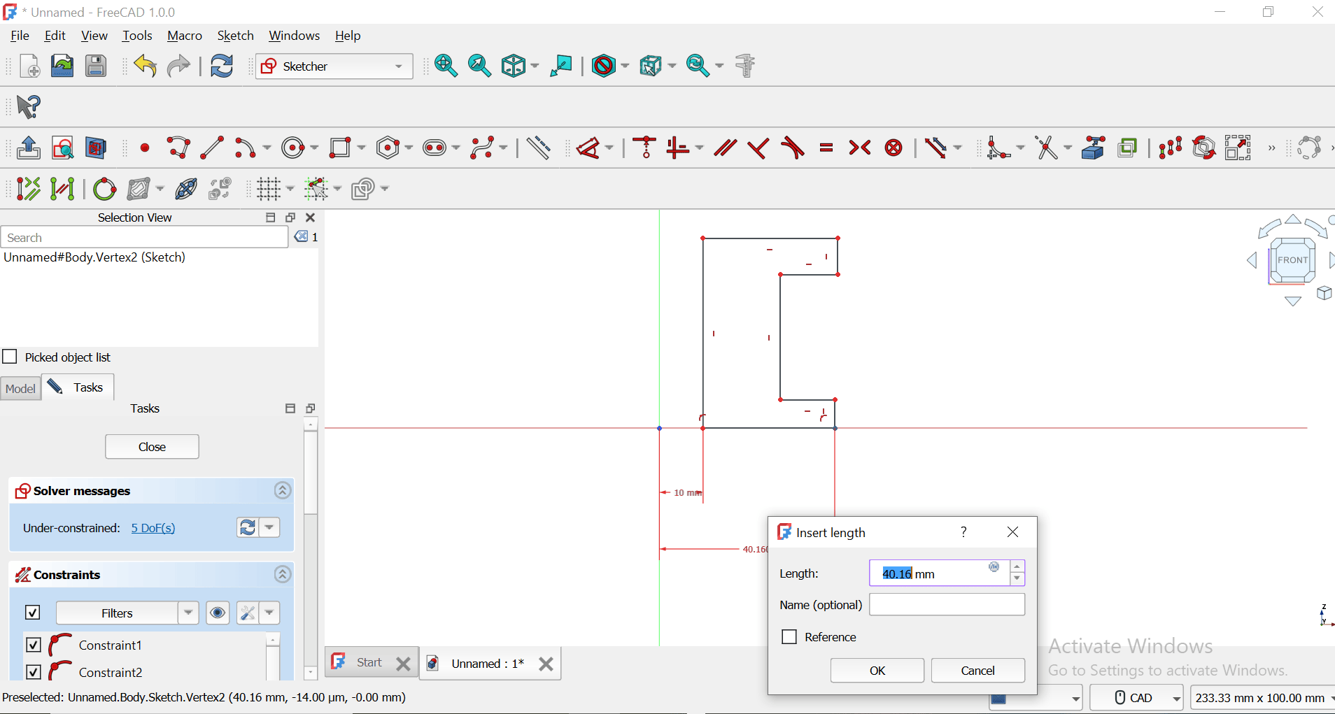
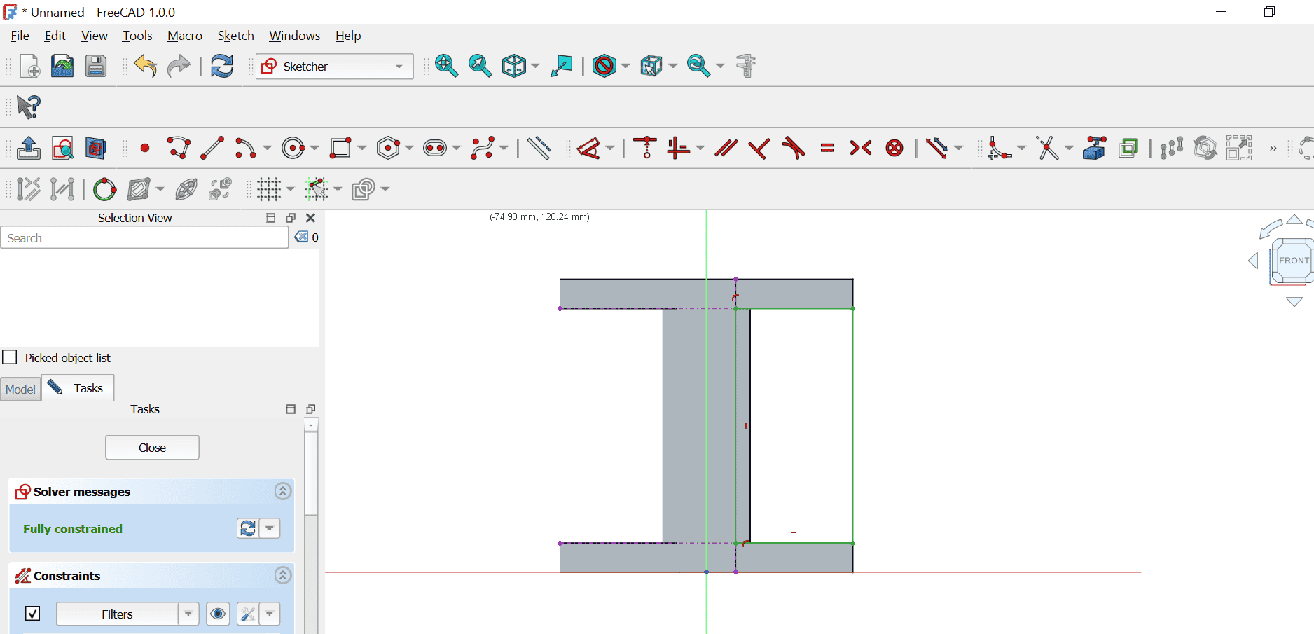
SKETCHING AND DIMENSIONING
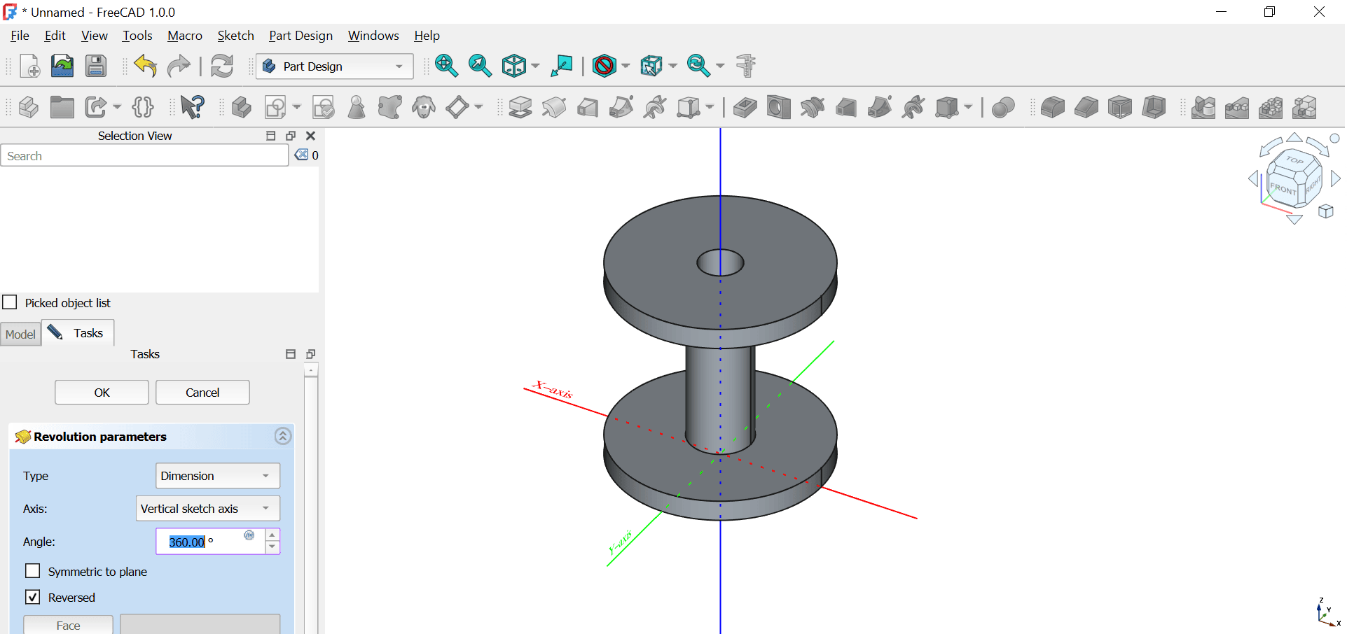
REVOLVING
THis is where I used a revolve feature to make a solid body from the sketch.
ADDING RIBS TO THE BODY
I started by making a new sketch on the body of the part.
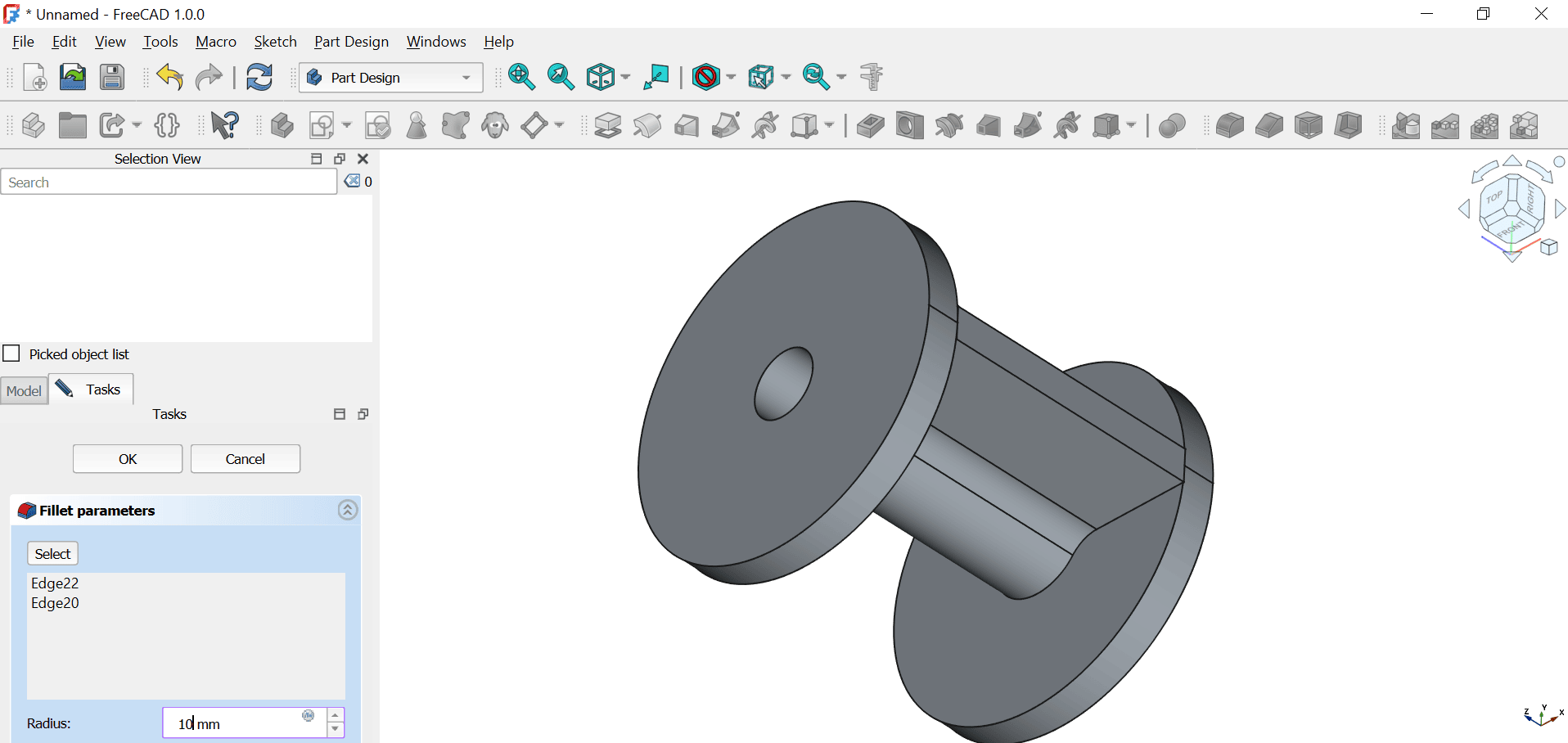
EXTRUDE
I used the pad to extrude the sketch I previously made and filleted it.
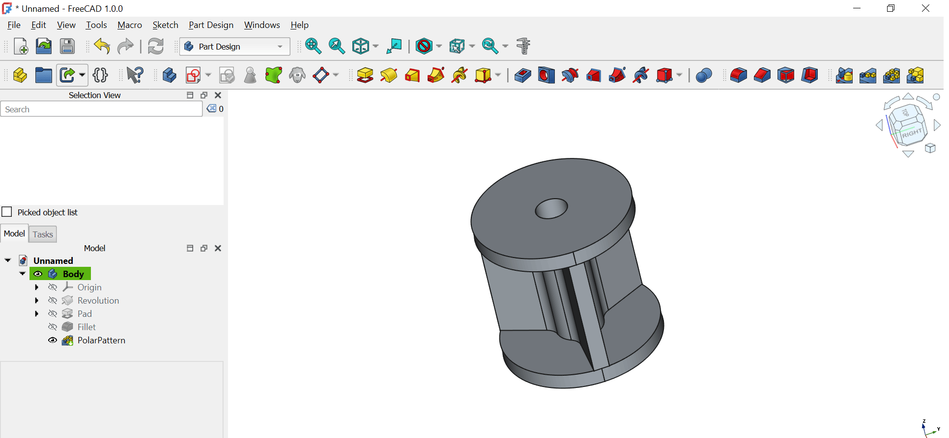
PATTERN
I patterned the rib I previously made around the revolution of the body of the part.
FILES
The files I have made using the above softwares can be downloaded below.