COMPUTER CONTROLLED MACHINING
 GROUP ASSIGNMENT
Computer-controlled machining, often referred to as Computer Numerical Control (CNC) machining, is a manufacturing process that uses computer programs to control machine tools such as lathes, mills, routers, and grinders. This allows for precise and automated production of parts and components. This method works through the following steps;
GETTING STARTED
1. DESIGN PROCESS
I started off by using Solidworks to design a product to machine/cut. I chose flat pack furniture,which do not need any use of fittings and fixings. The furniture to cut is something that has to be useful in one of the laboratories where I work.PARTS CREATION
I launced solidworks then created different parts of the furniture to cut. The pictures of creating parts are as follows;
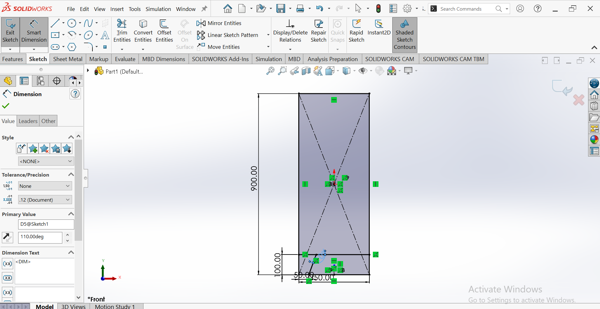
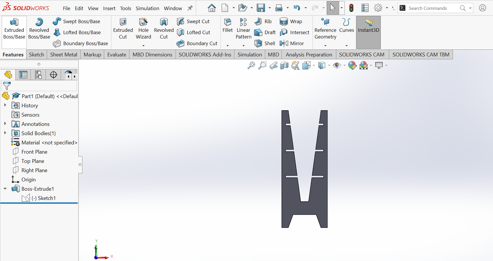
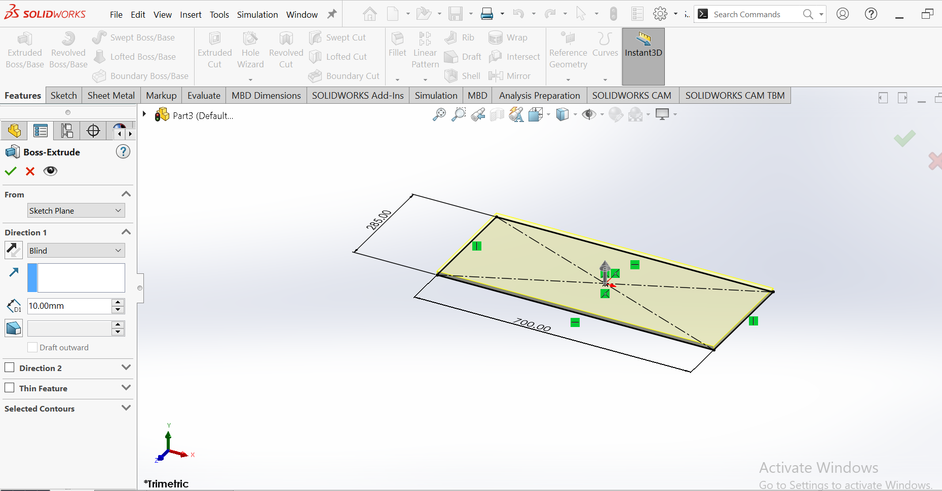
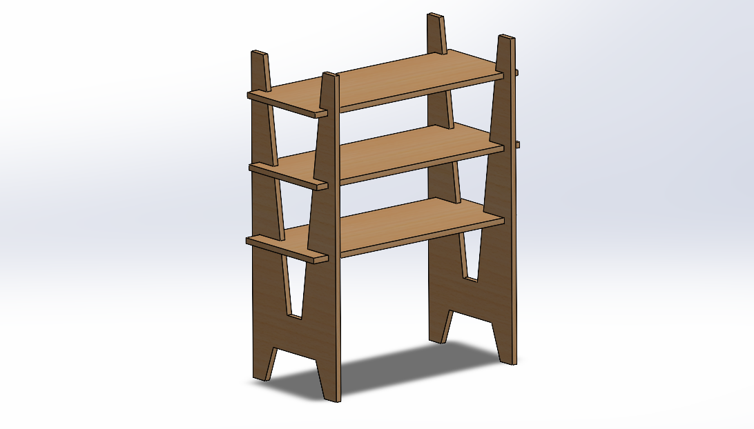
The final product looks like this:
The parts were then saved as dxf files and opened into a CNC machine (router), VCarve to create g-codes that will be readable by the machine.
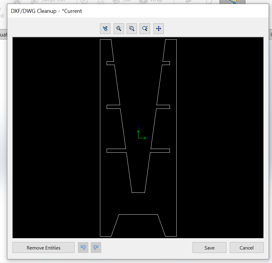
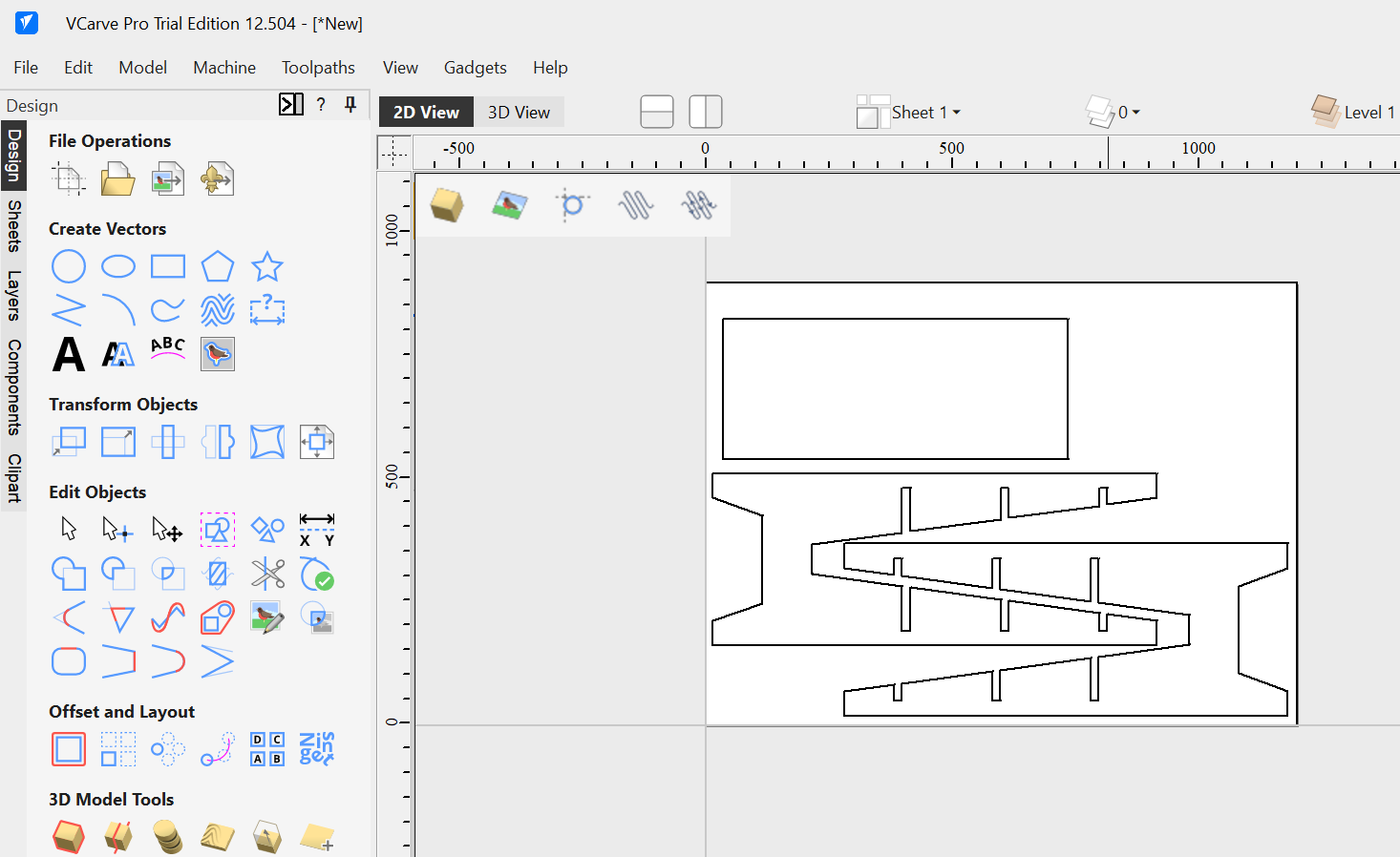
Importing the dxf files and then nested them in the sheet to make sure the sheet is used efectively.
Tool setup- I selected 6mm tool with 3 flutes for cutting my 16mm MDF board. The depth of each pass was set at 2.5mm. This was to enable clean cuts, without burns in the board and also to protect the cutting bit. After that I calculated the the toolpath, g-code where it will be read by the machine.
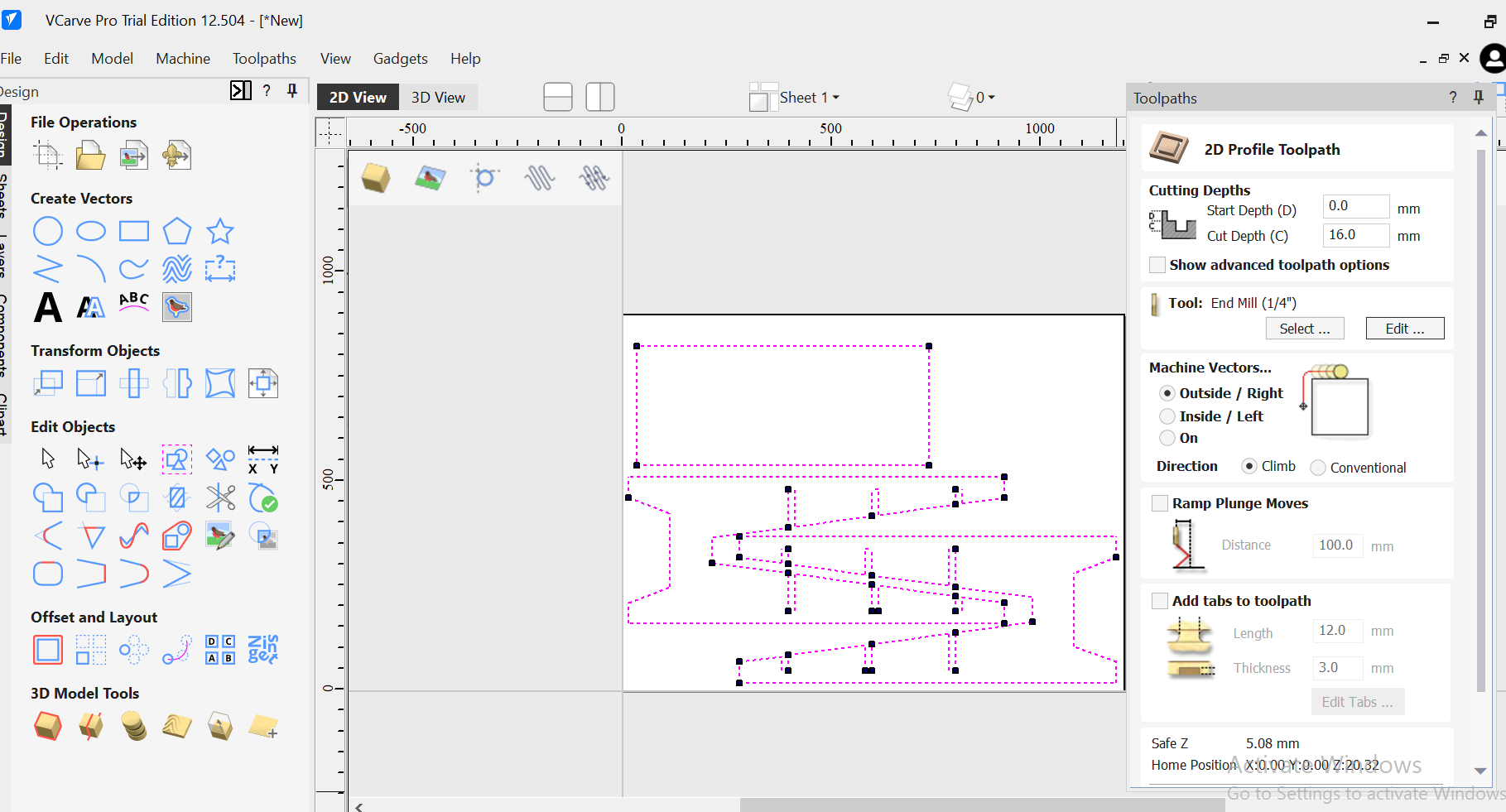
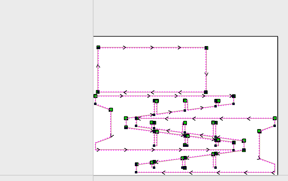
The toolpath was then made and this is how like and its simulation.
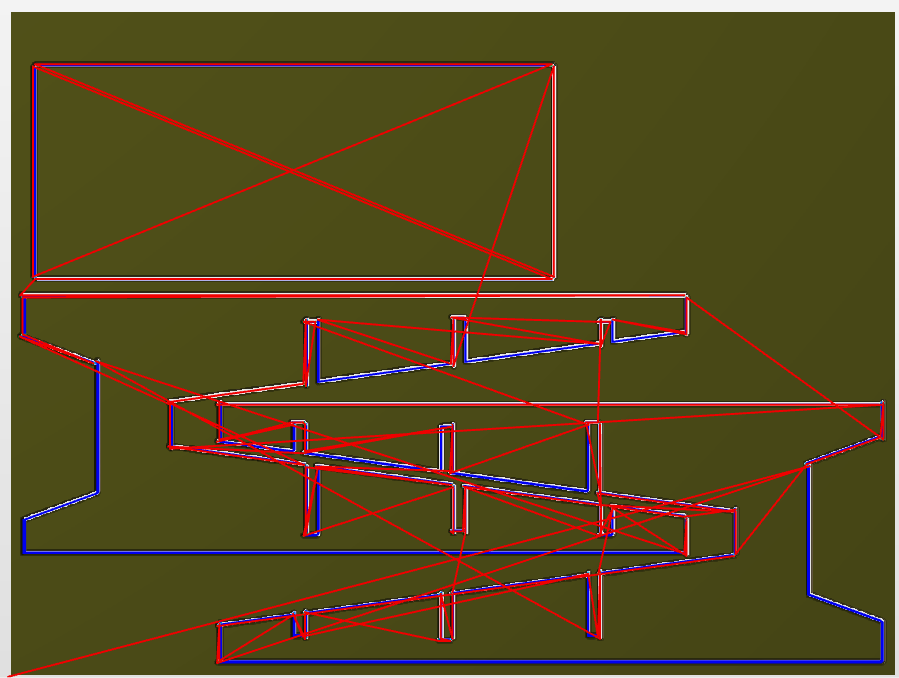
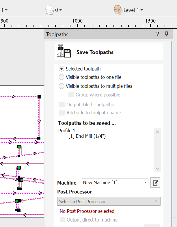
Exporting the toolpaths as G-code for the CNC router to read it.
Saving the files as g-code.
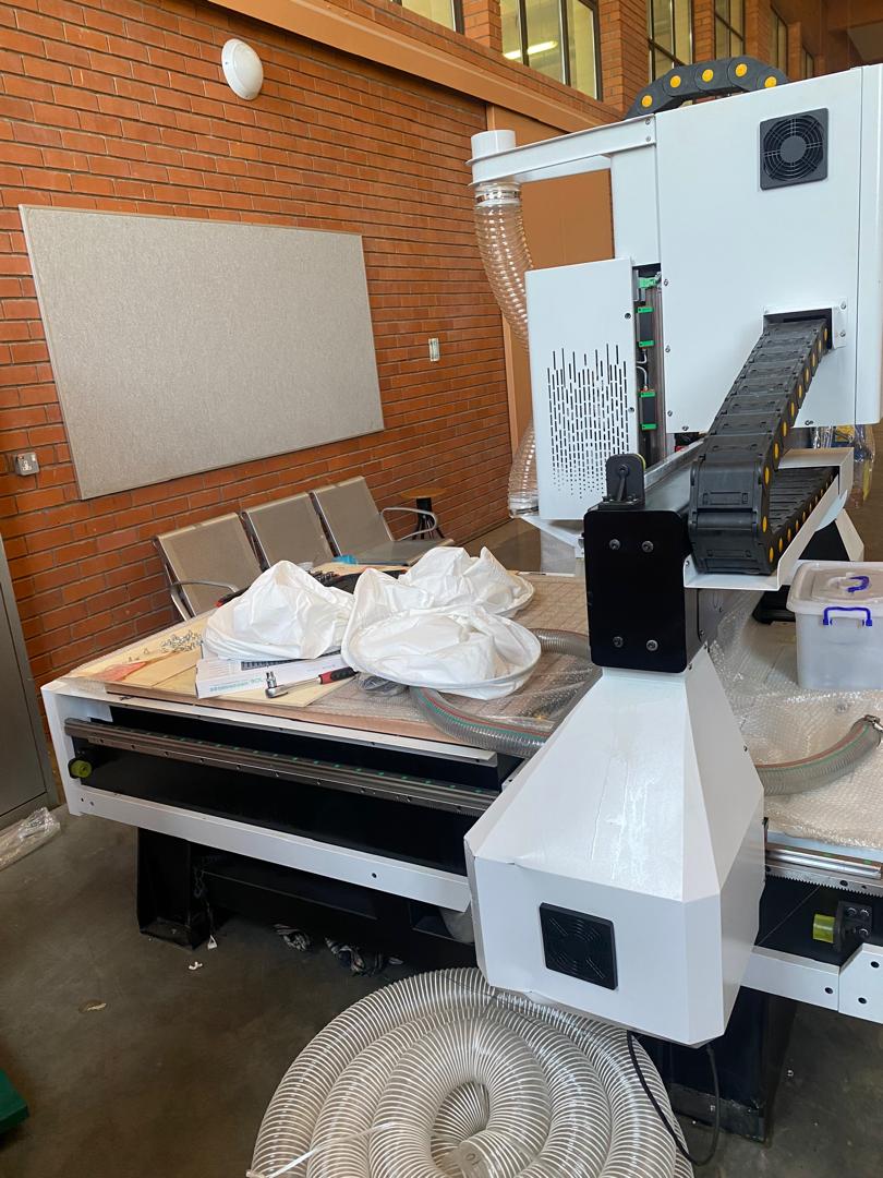
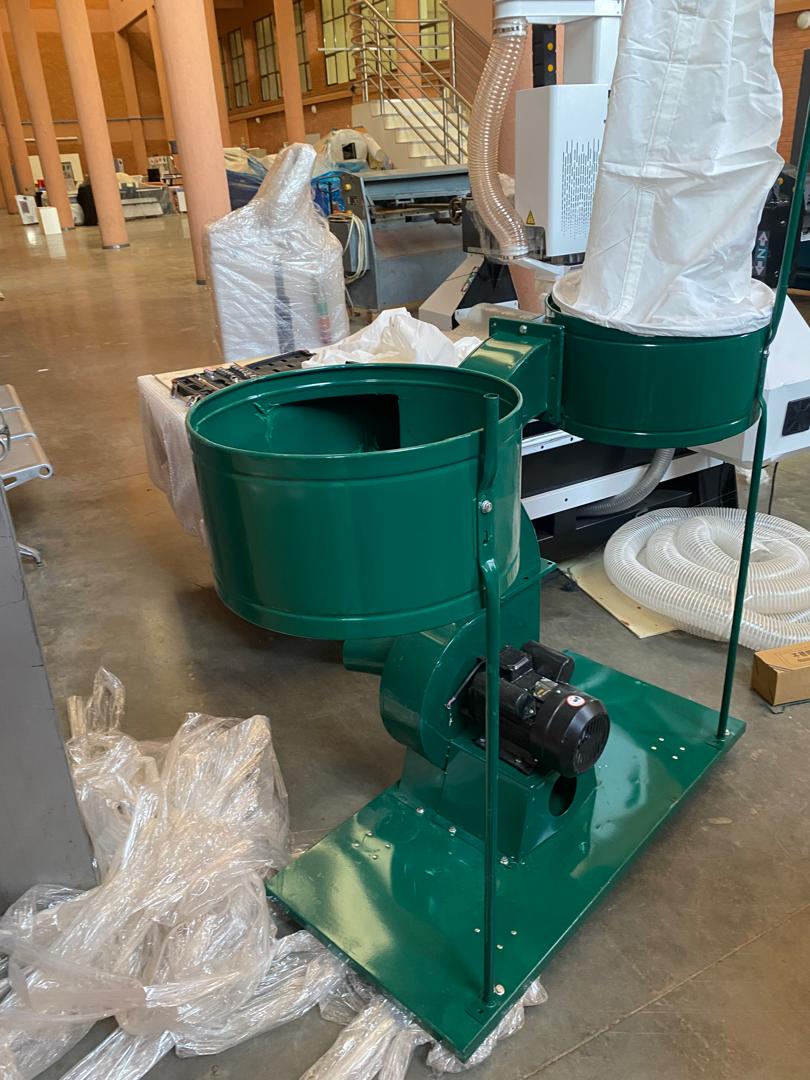
I could not fabricate or machine the parts because our CNC router is still down at the moment and also the newly bought one is still under commissioning
FILES
The files I have made can be downloaded below.