Week 12 Mechanical design, Machine design
Making a cnc
This week it was time to design the CNC machine in teams. I oversaw designing all the mechanisms and parts, as well as the structures. Below is my contribution to the team.
Before continuing, it's best to show the assembled machine from the program

The rest of the parts were a design inspired by the PRUSA MK4S 3D printer, which are:
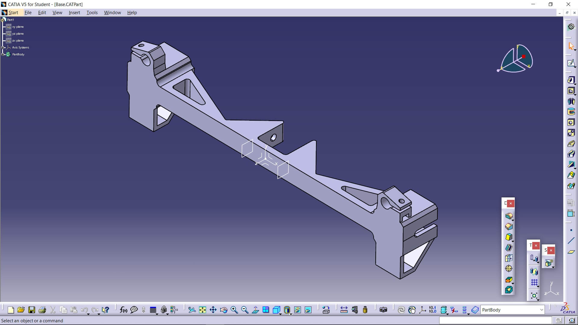
Base
This is one of the two parts that join the base of the CNC. Their functions are to hold a pulley for the belt that moves the Y-axis carriage, to hold the two smooth rods for the same Y-axis carriage, and lastly, the most obvious function, to join the base profiles.
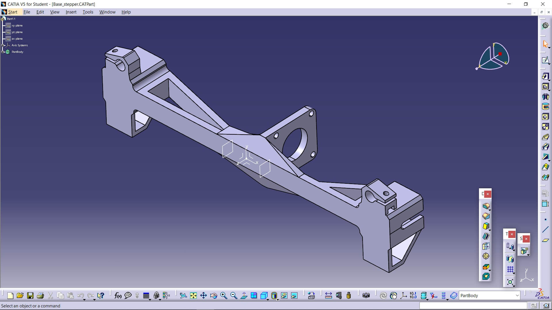
Base_stepper
This part has the same functions as the previous one, but with the difference that this one doesn't hold a pulley, it holds the entire stepper motor.
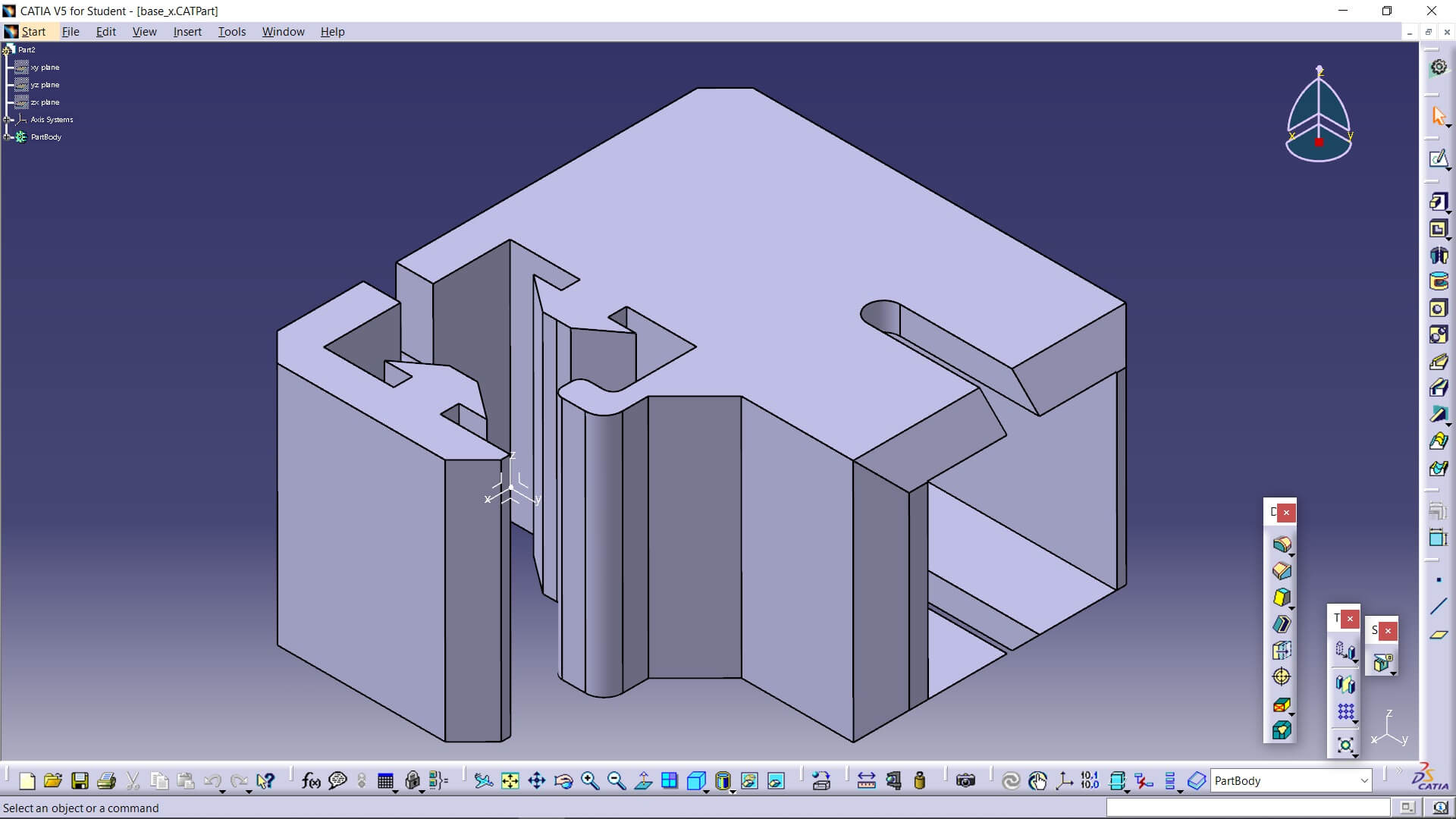
Base_x
This part is for joining the profiles of the base square and the ones that hold the X-axis.
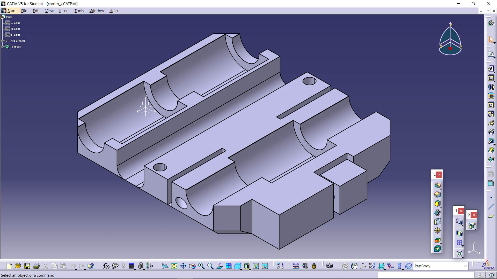
Carrito_x
As its name suggests, this is one of the two parts of the carriage that travels along the X-axis. It has 3 slots for linear bearings each, another 2 to insert the belt, which are tightened with screws, a hole between the bearing spaces so the belt can move freely, and a space on the top to place a servo motor.
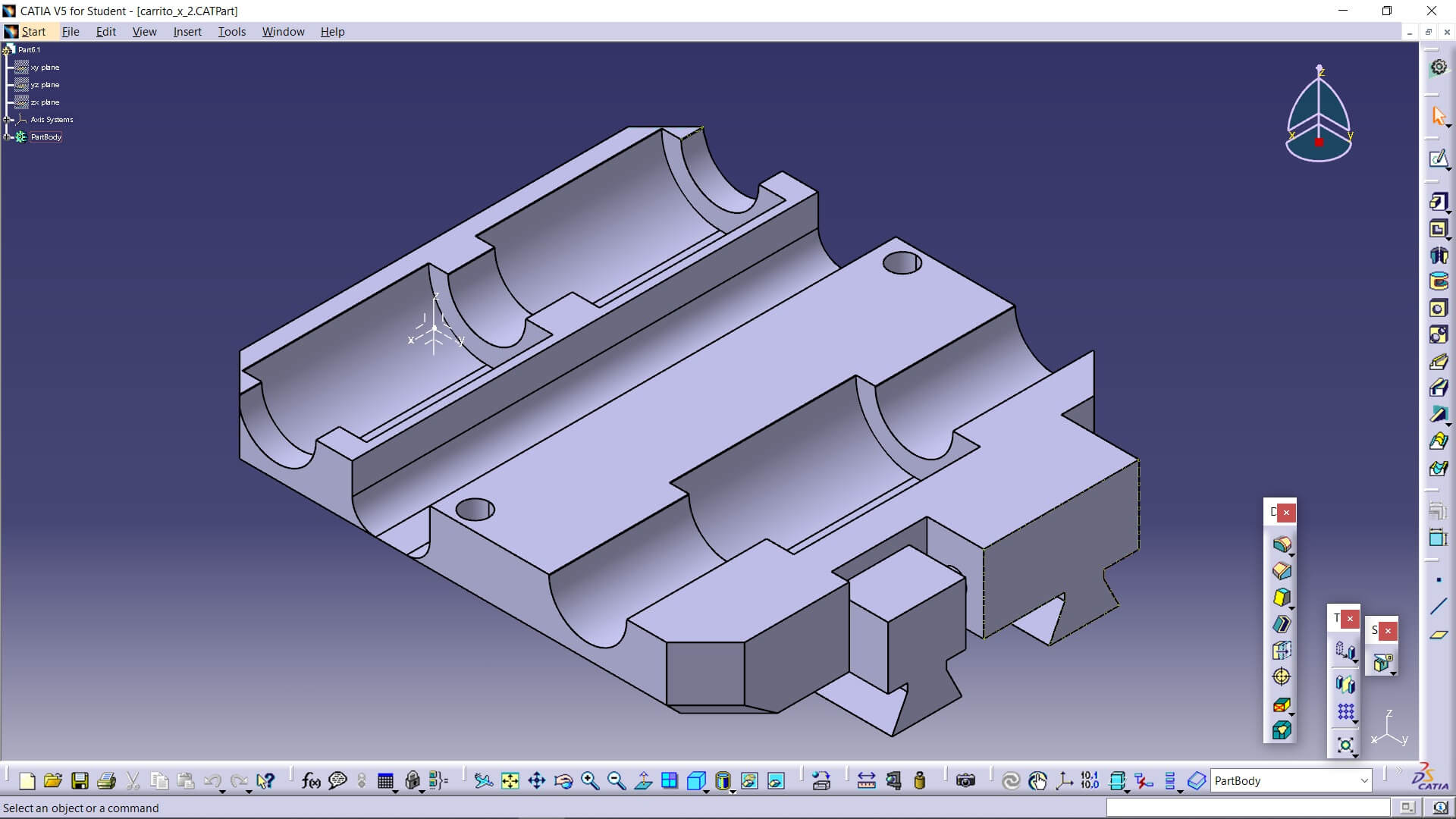
Carrito_x_2
Being the second part of the carriage, it has the same slots except for the ones to hold the belt. On the other hand, it has two trapezoidal shapes on the back that act as rails so that our spindle moves up and down without wobbling.
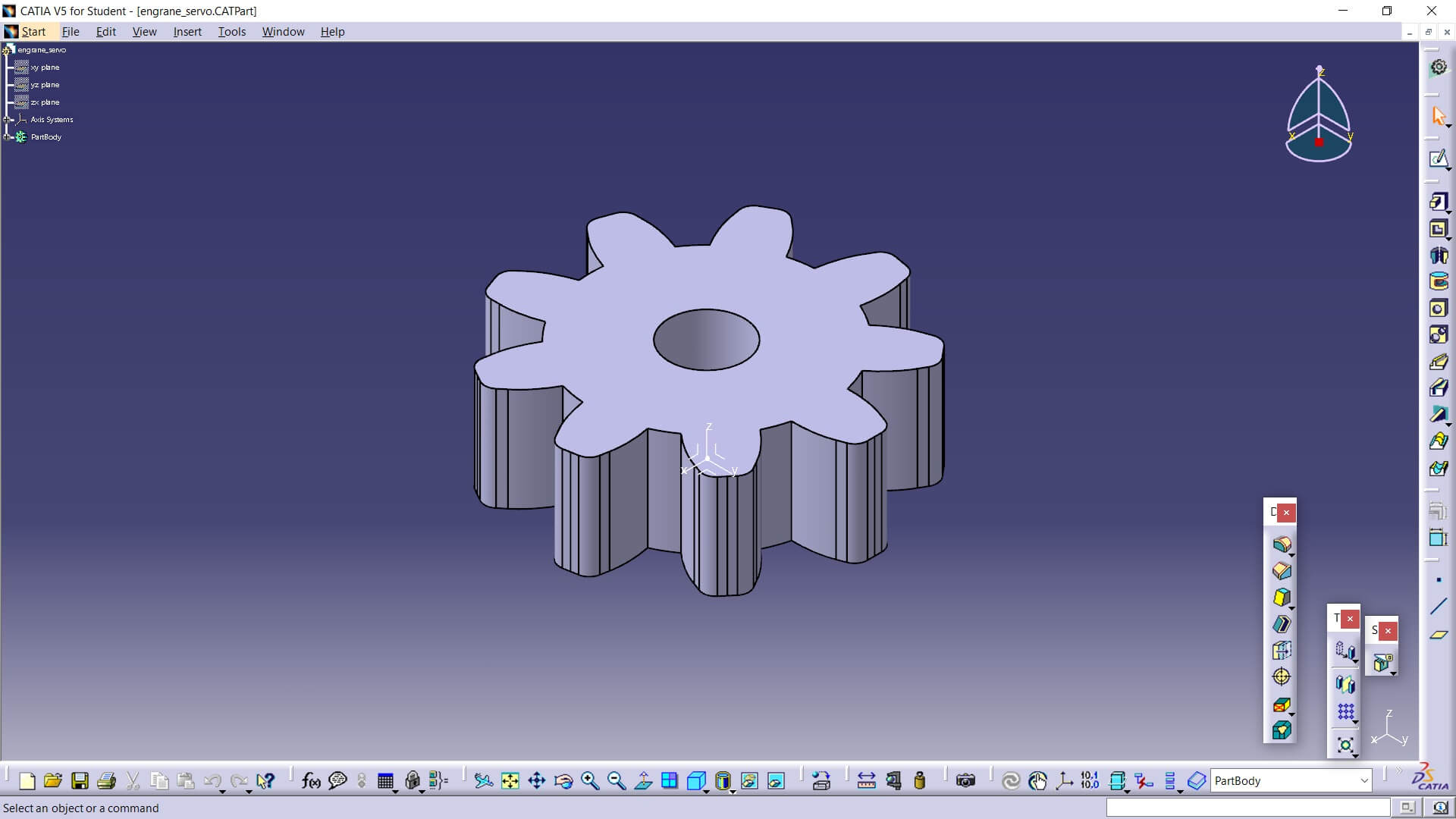
Engrane_servo
This gear is the one that moves the spindle holder up and down.
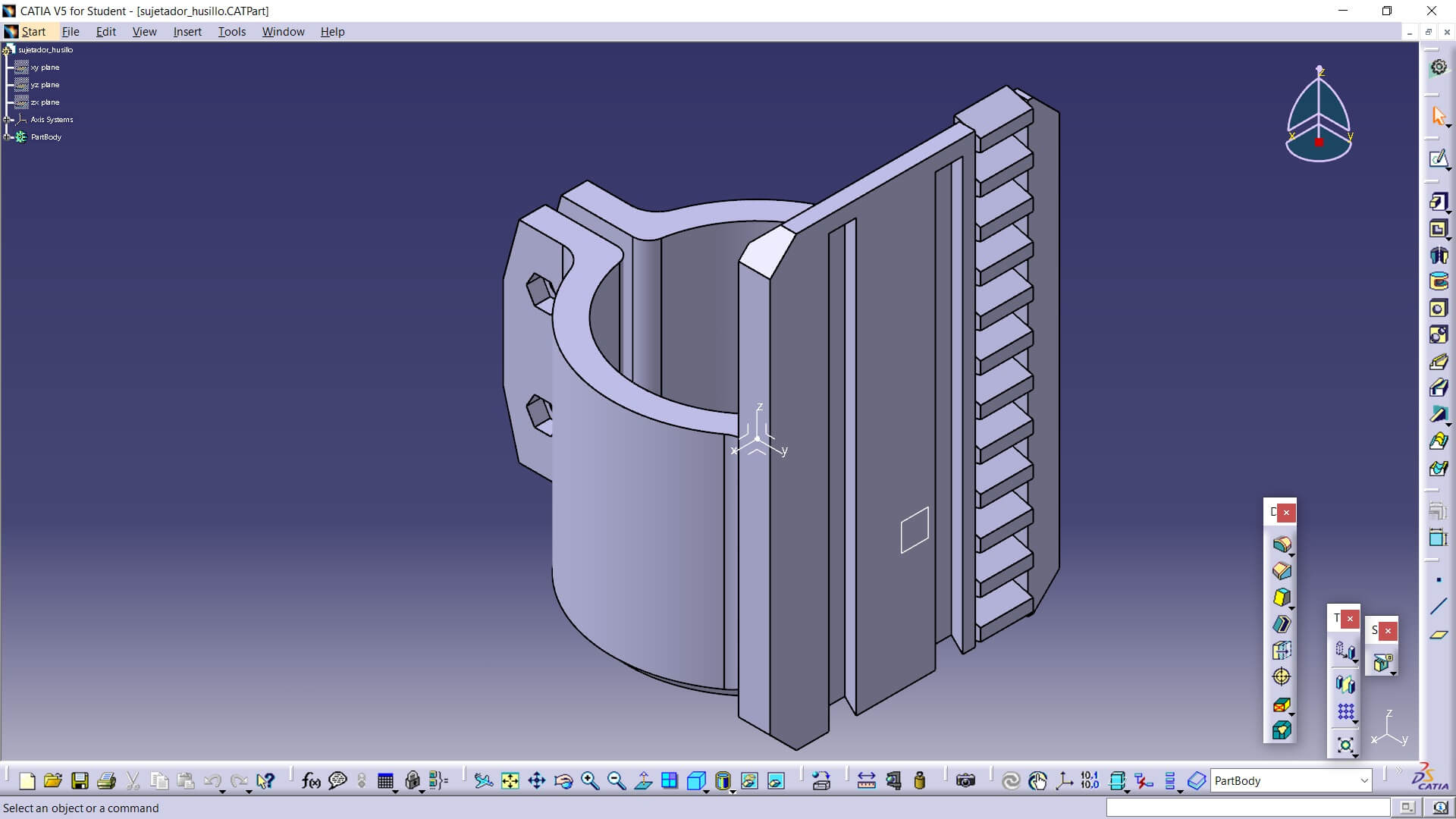
Sujetador_husillo
As the name suggests, it holds the motor that rotates the spindle. It has a couple of tabs to tighten the motor and prevent it from rotating. On the back, as can be seen, it has 2 trapezoid-shaped holes that function as rails and has a rack so the gear can move it up and down.
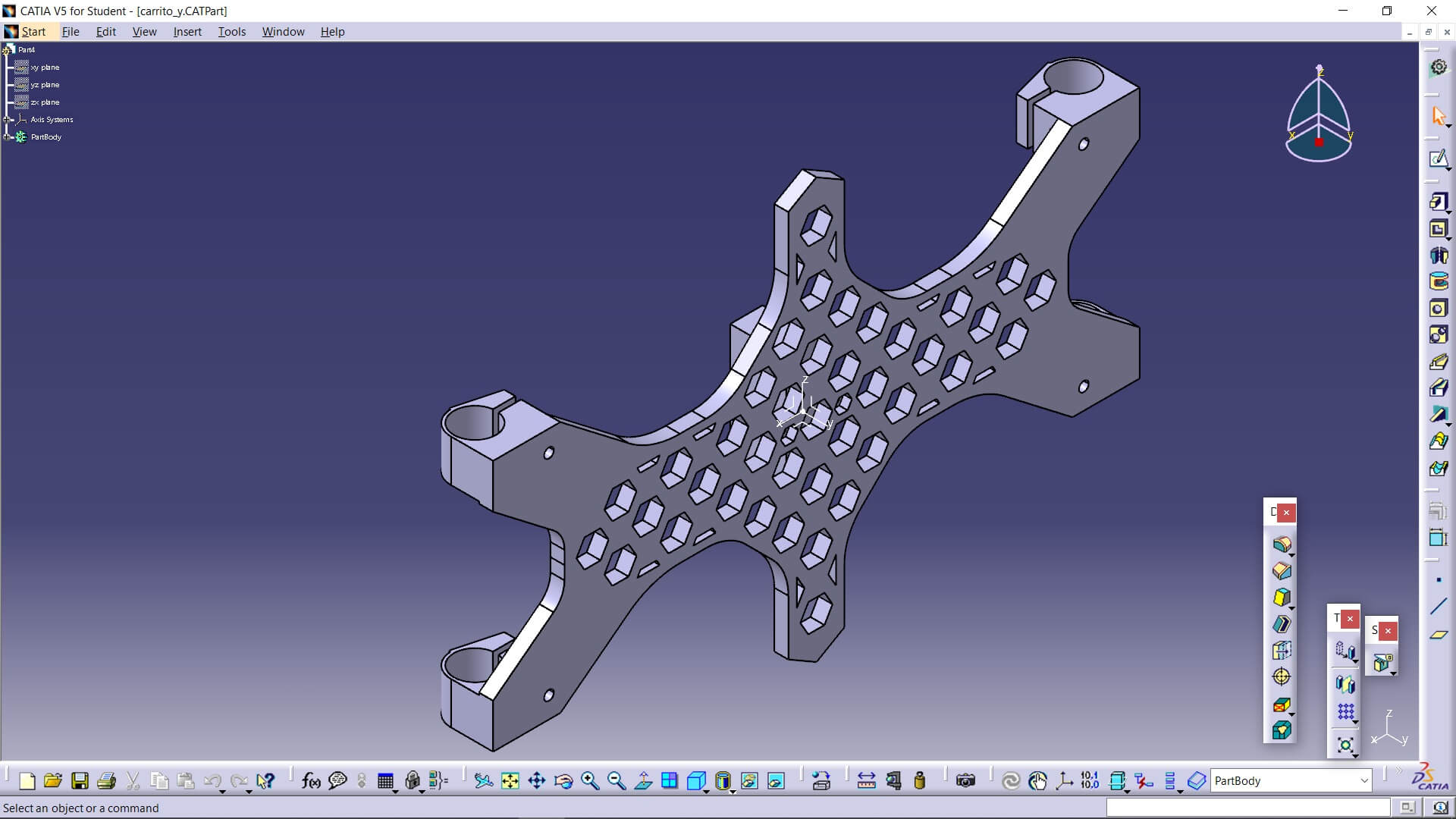
Carrito_y
The Y-axis carriage has 4 spaces to place the corresponding bearings. Also, the hexagonal holes have no function beyond saving material, and that shape was chosen because it has the best force distribution, like a honeycomb.
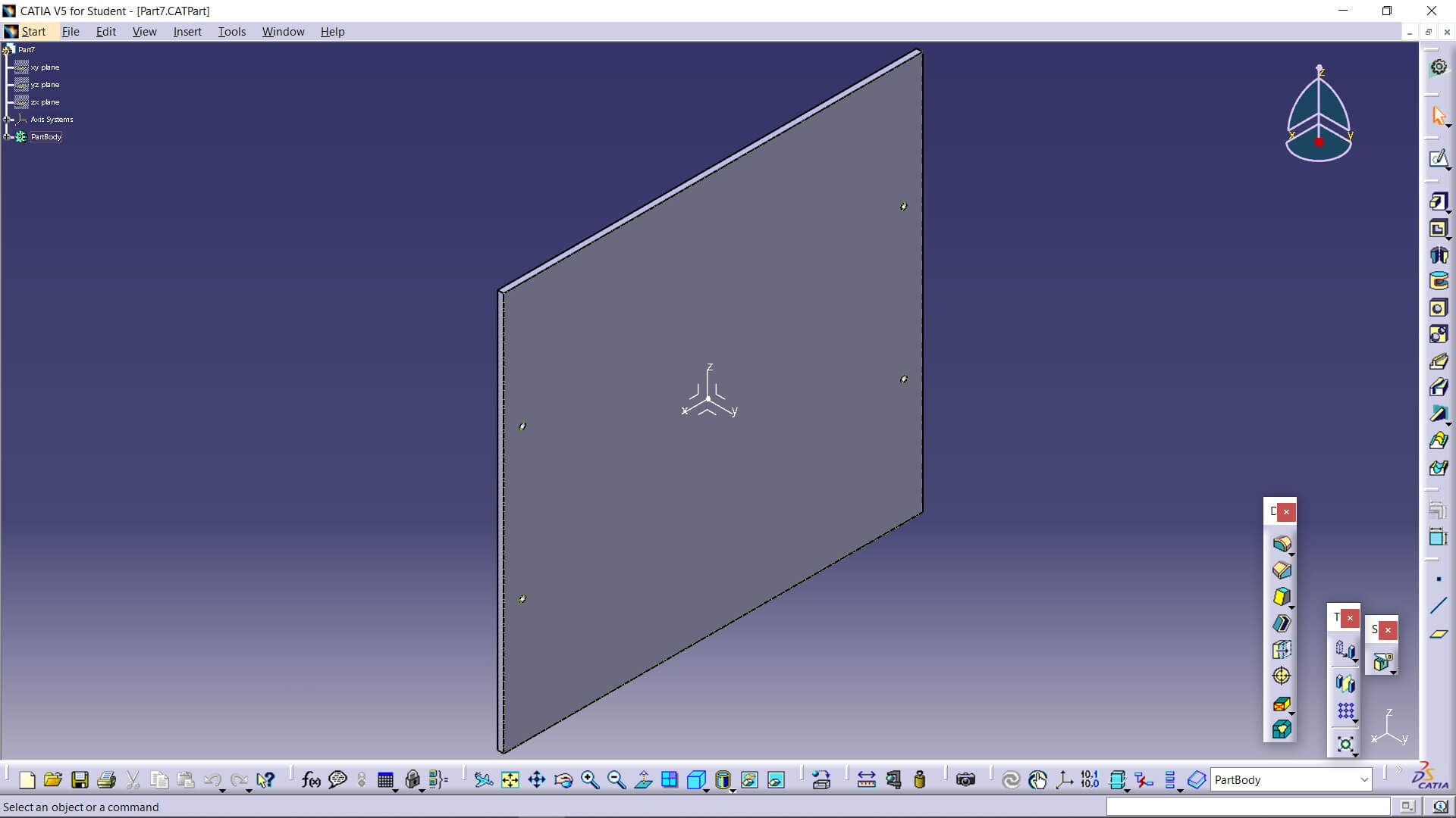
Cama
This is the sacrificial bed for CNC.
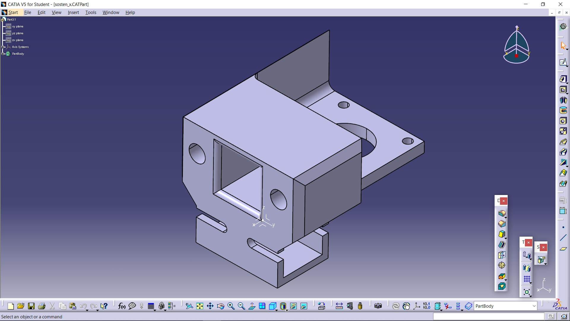
Sosten_x
This is one of the two parts that support the X-axis. It holds the stepper motor, both smooth rods for the Y-axis, and is mounted on a profile with a couple of screws.
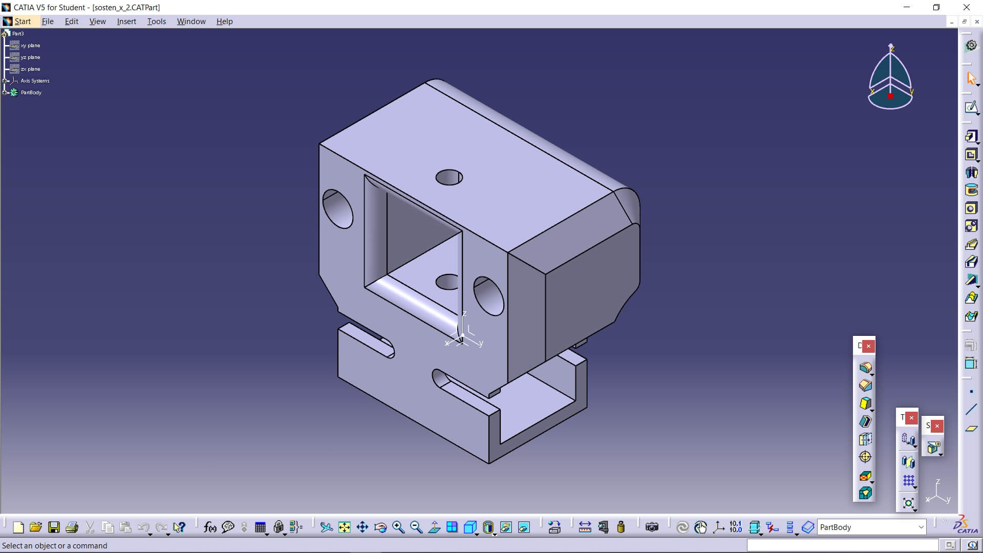
Sosten_2_x
This is the counterpart of the previous part. It has the same functions but holds a pulley.
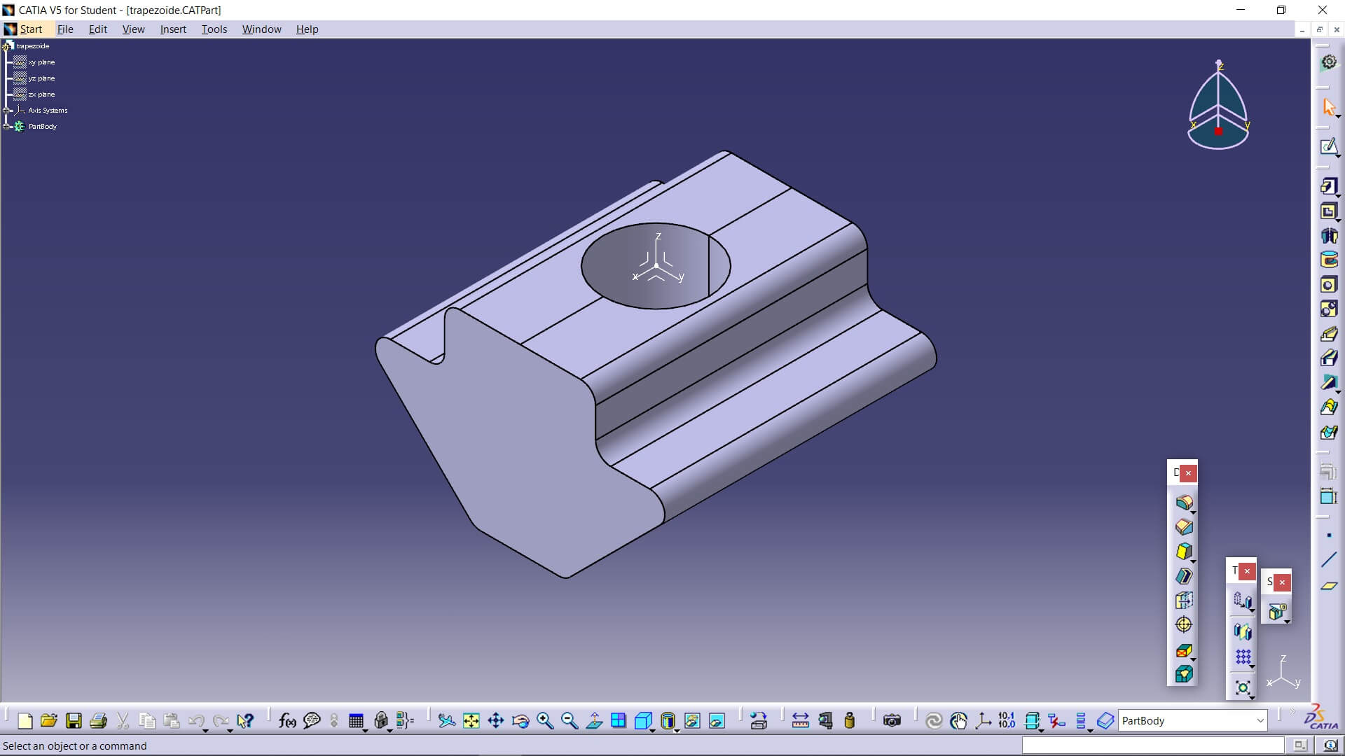
Trapezoide
The only function of this part is to be inserted into the profile slots and hold screws to attach parts to the screws themselves (this is not visible in the machine assembly, as it’s not necessary to hold anything there, but it is used in the actual machine).
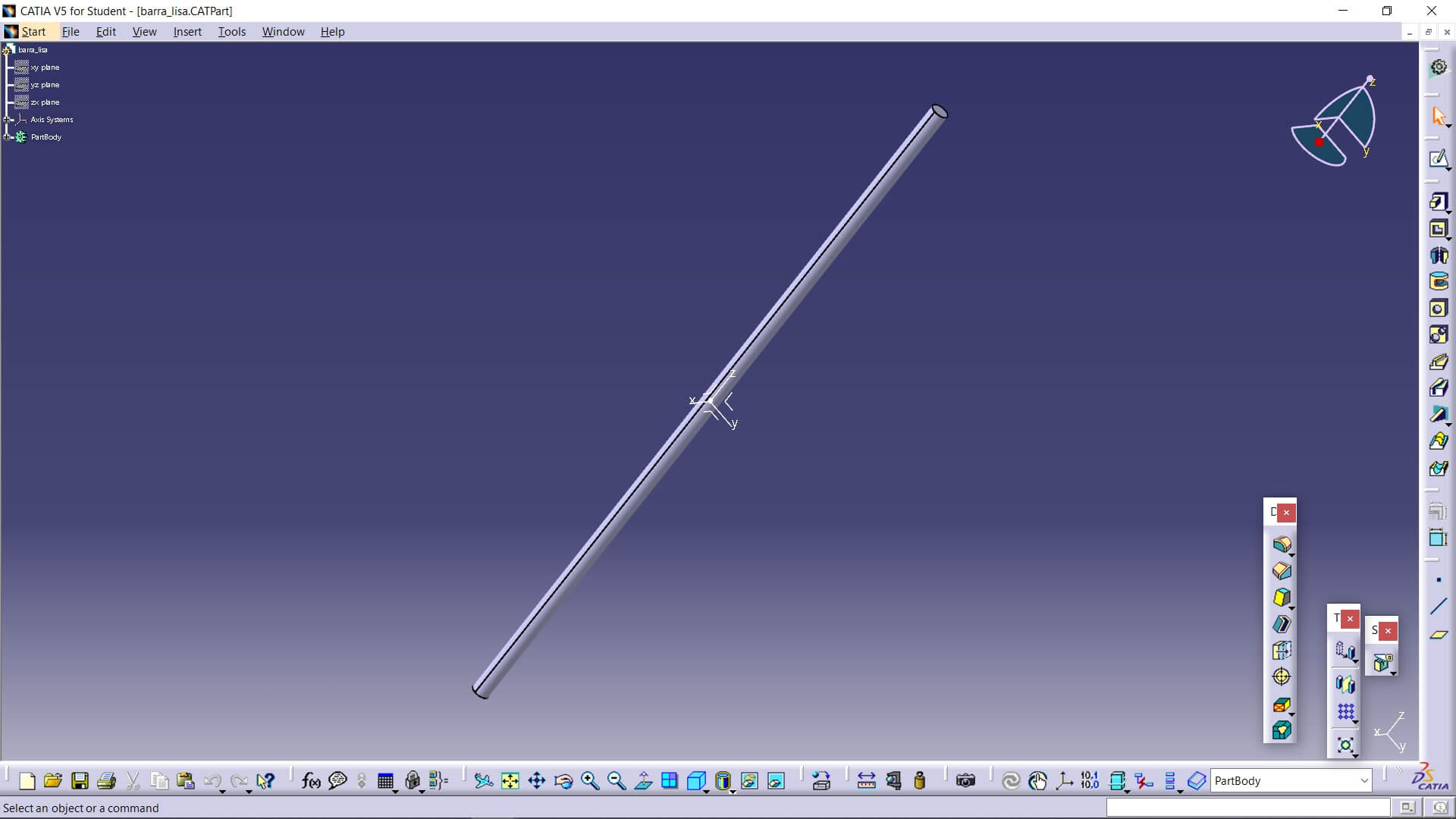
Barra_lisa
This simulates a generic smooth rod, and since it wasn't hard to replicate, the file was not downloaded from the internet.
Now then, here are the problems I had; first, the parts that connect the base profiles were not very firm and would bend, so I added some triangles on the edges to give them more strength. The belts on both axes were not tightening properly, so I placed them in a diagonal arrangement toward where the belts enter, so that when installed, they would push the belts inward and leave them well tensioned. The bed was not balancing properly, so I gave it a cross shape to have better reach with its support area. The X-axis of the machine was twisting slightly, so in this case I added another profile with a couple of angles on the top. That resulted in a better structure.
Here you have the link to our group page
For the parts used within our CNC, there are some that we did not design ourselves because they are components that were purchased. Therefore, their 3D designs are available online, which are:
Here you can find the link to the external files:
Here you can find the files of my own: