Plastic injection molding machine
Approach

For my final project, I decided to build a plastic injection machine. Here, I show the process and my line of thinking.
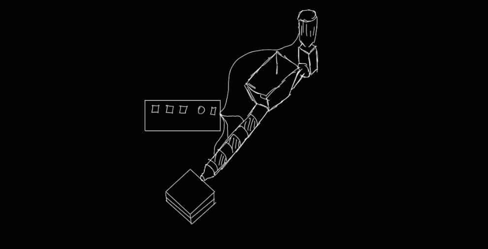
A plastic injection molding machine is a machine used in the industry to manufacture plastic parts through the injection molding process. This is one of the most common methods for mass-producing plastic components, such as automotive parts, toys, household appliances, packaging, and more. How does a plastic injection molding machine work?
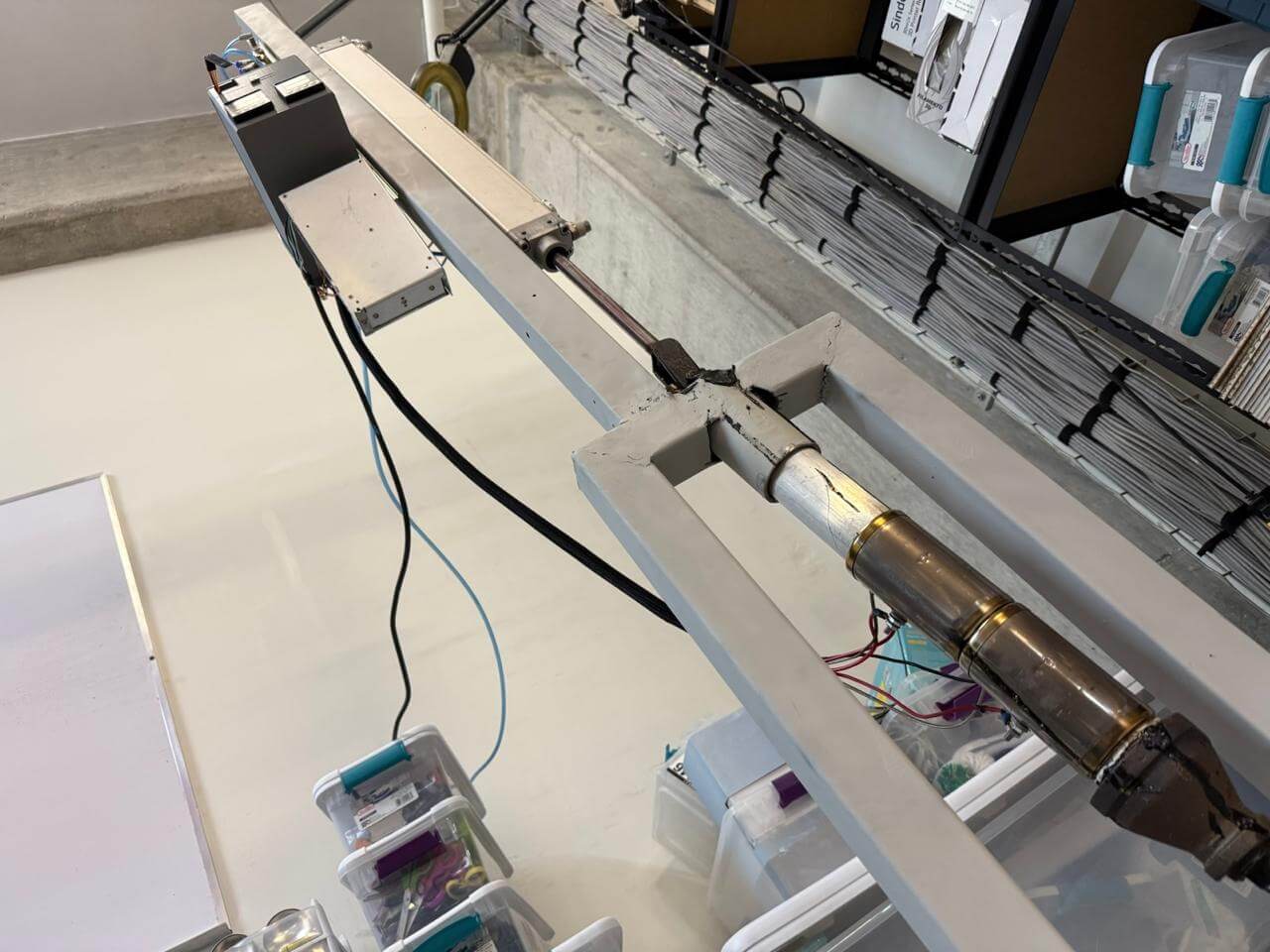
The original idea for this project was a machine with its tube in a horizontal position, using a motor to drive a leadscrew. However, that was too complicated, so I decided to go with a vertical setup instead, using a pneumatic piston to push all the contents at a constant speed.
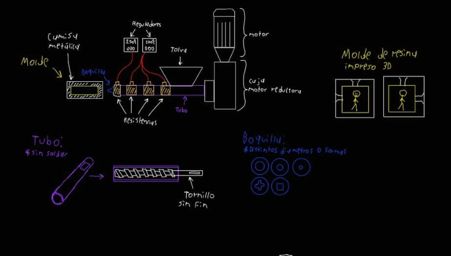
The first step was to decide what I wanted to use: a leadscrew or a piston to push the contents. Due to complexity, I chose the piston since it was simpler. It’s worth noting that I was already aware it wouldn't be easy to achieve a homogeneous mixture or to eliminate air bubbles in the mix, but it could still work.

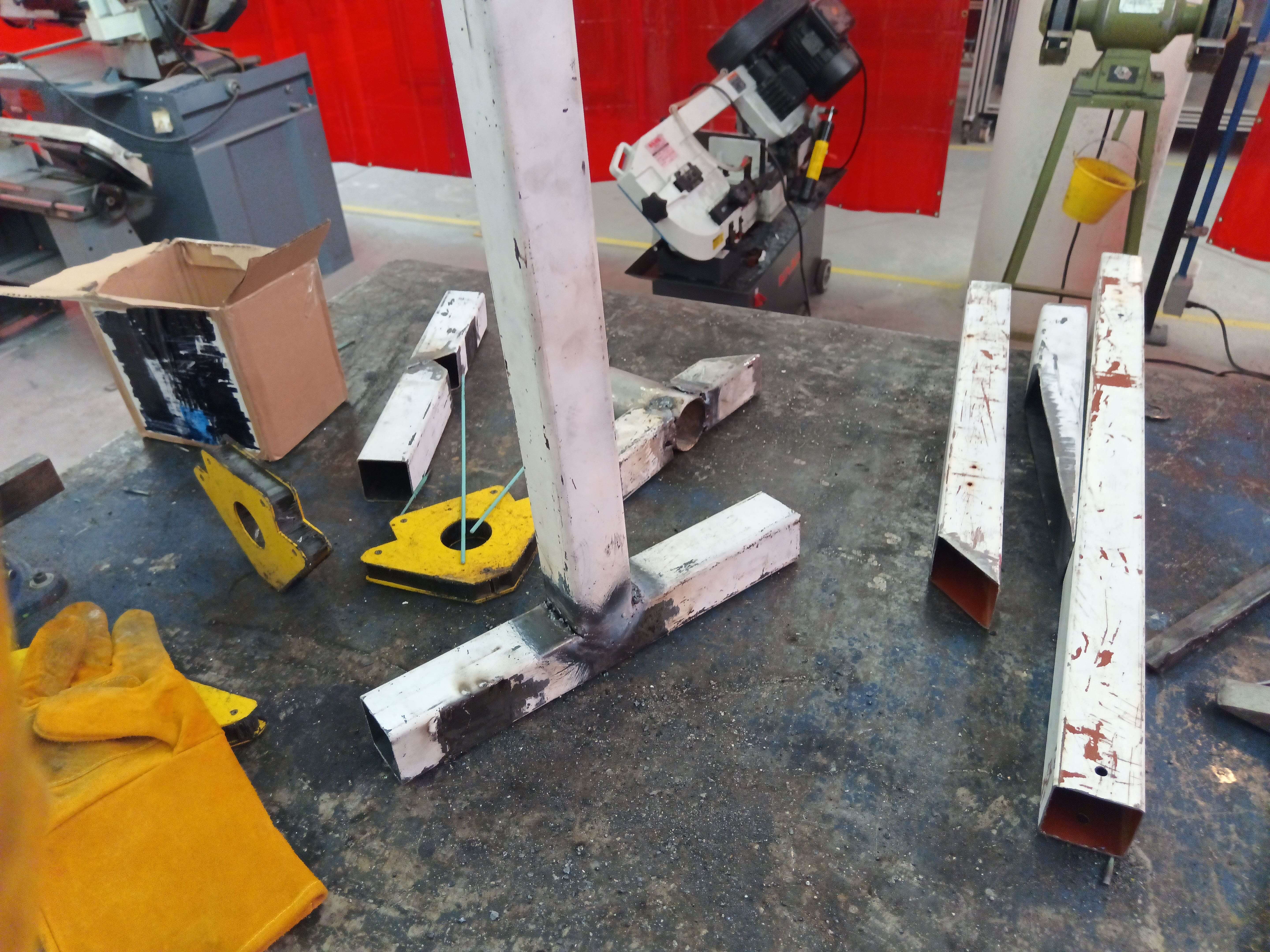
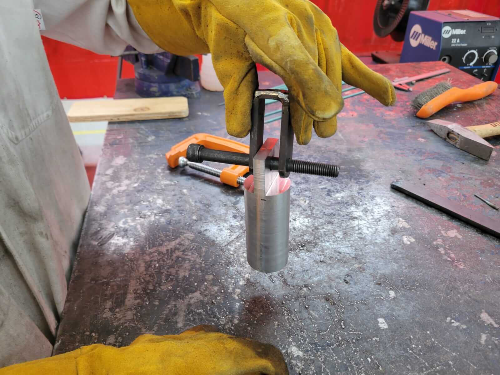
This part was simple, as it just involved measuring, cutting, welding and painting pieces of metal, as shown in the images.
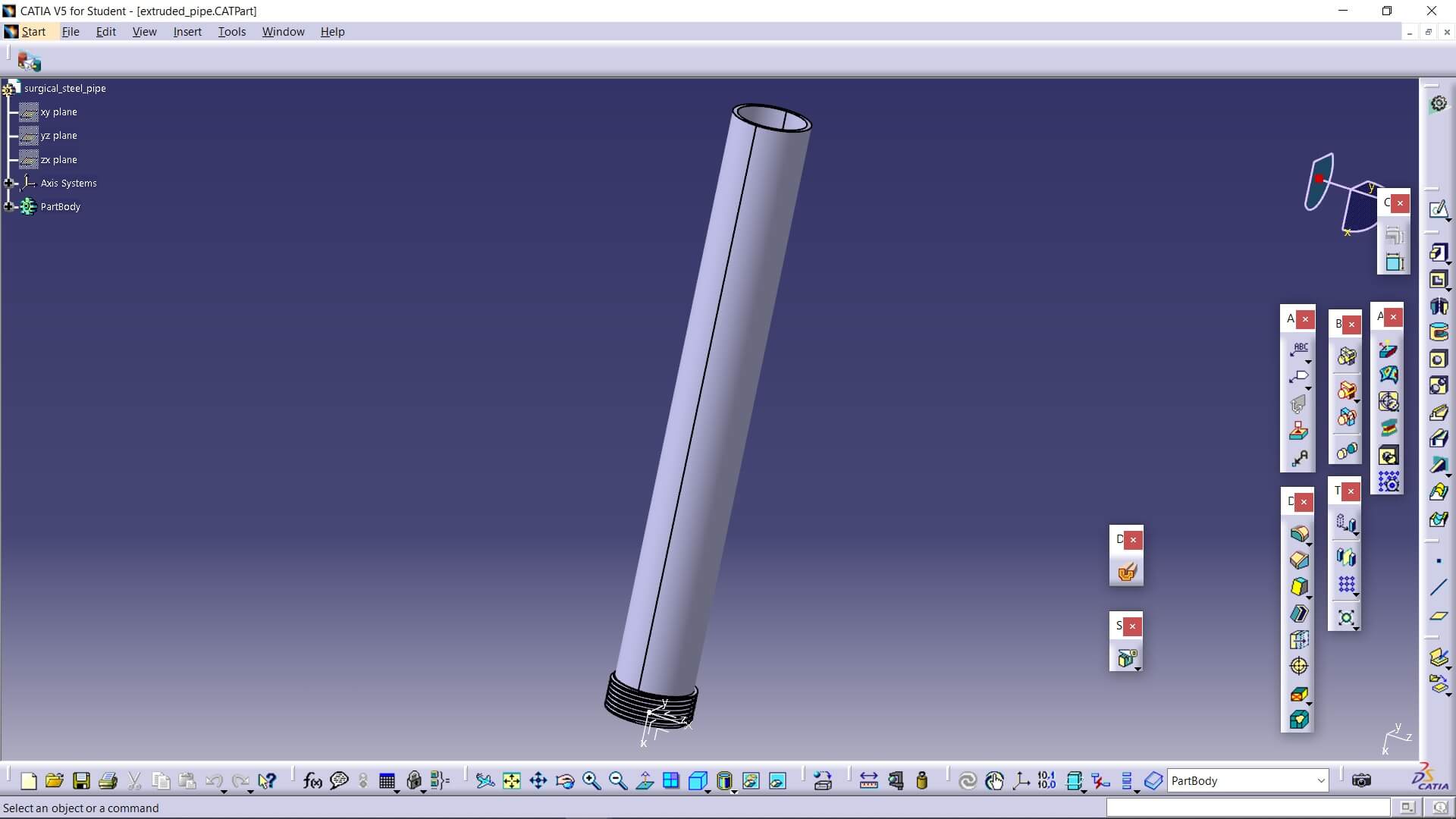
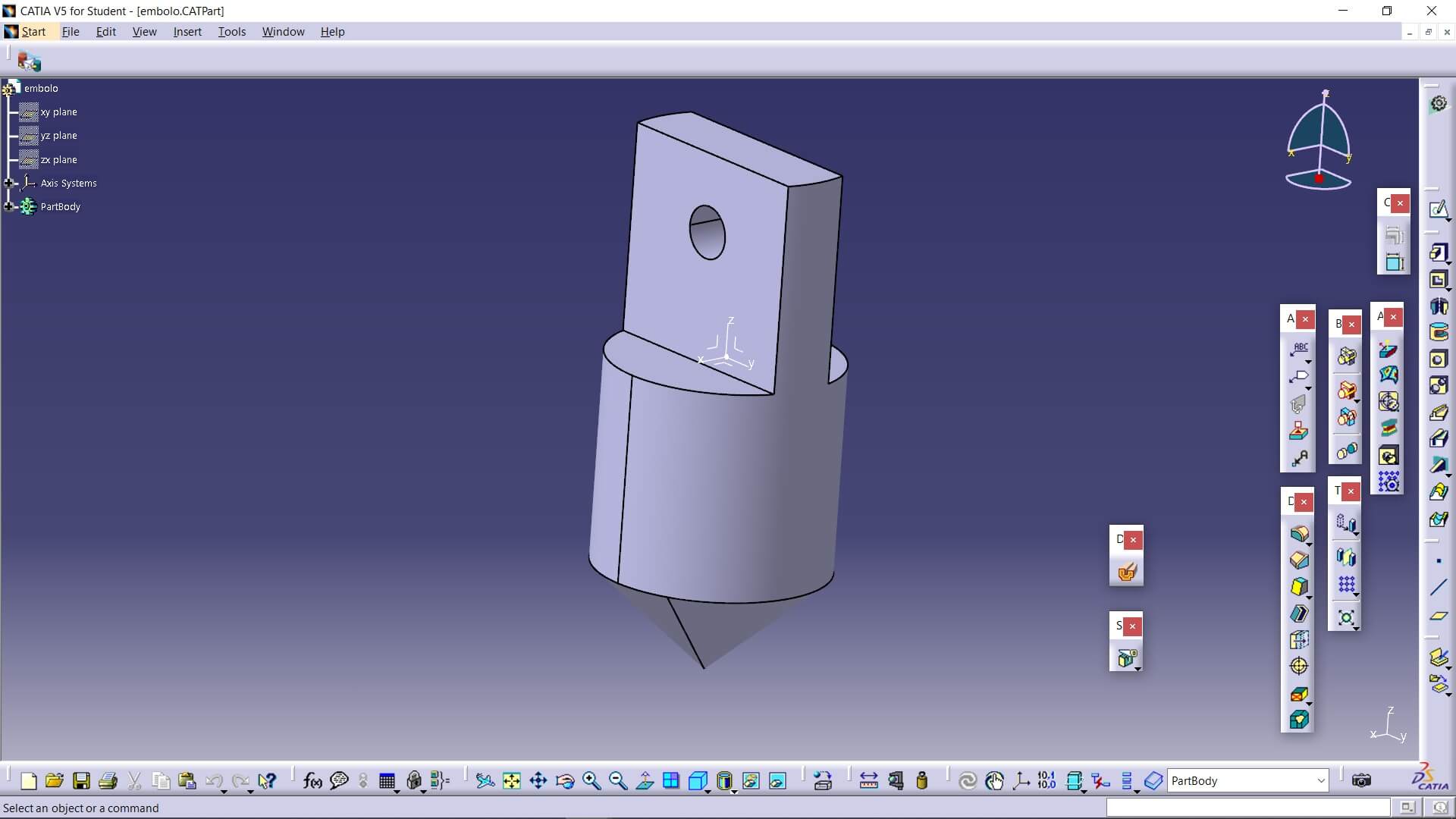
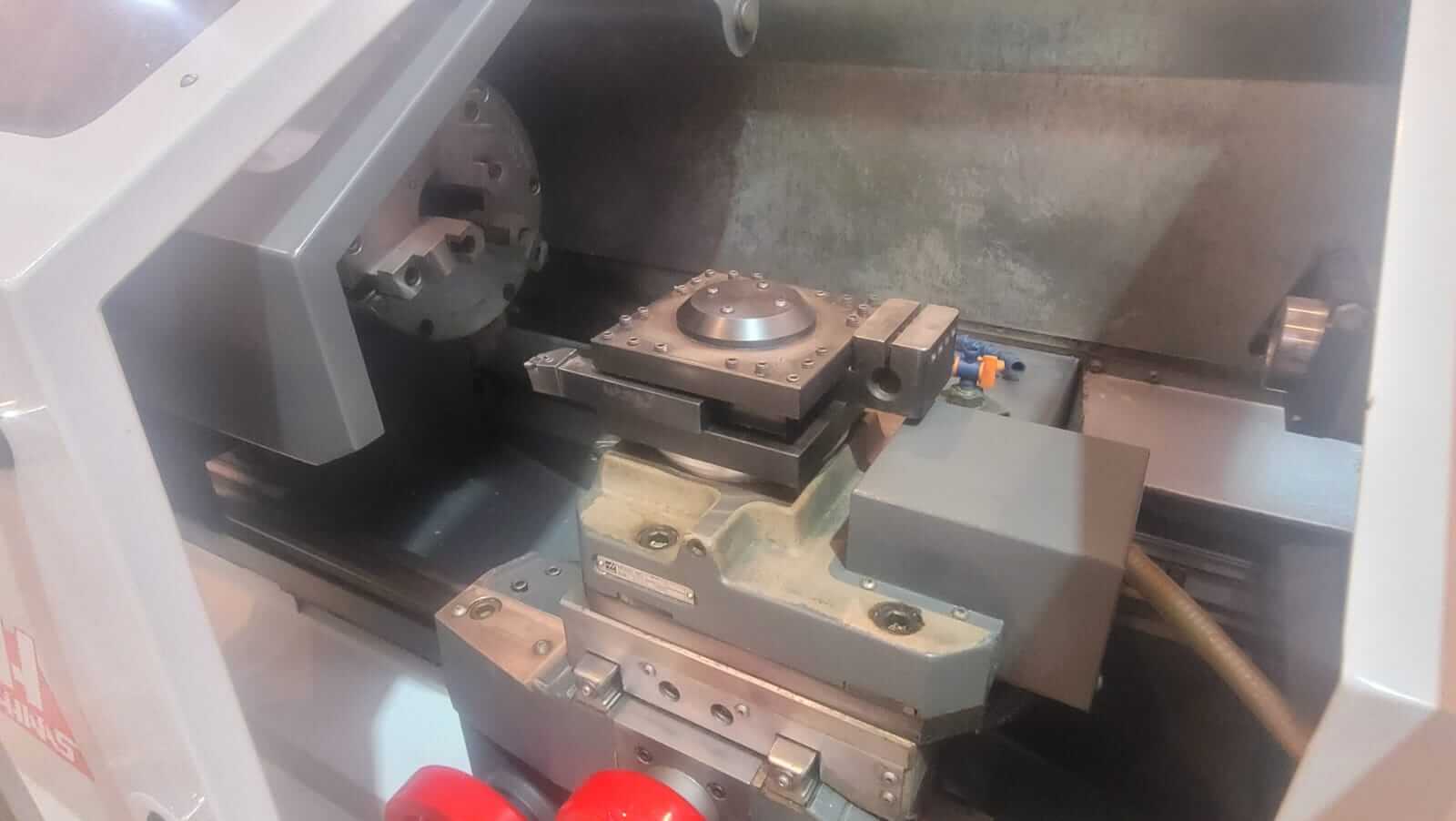
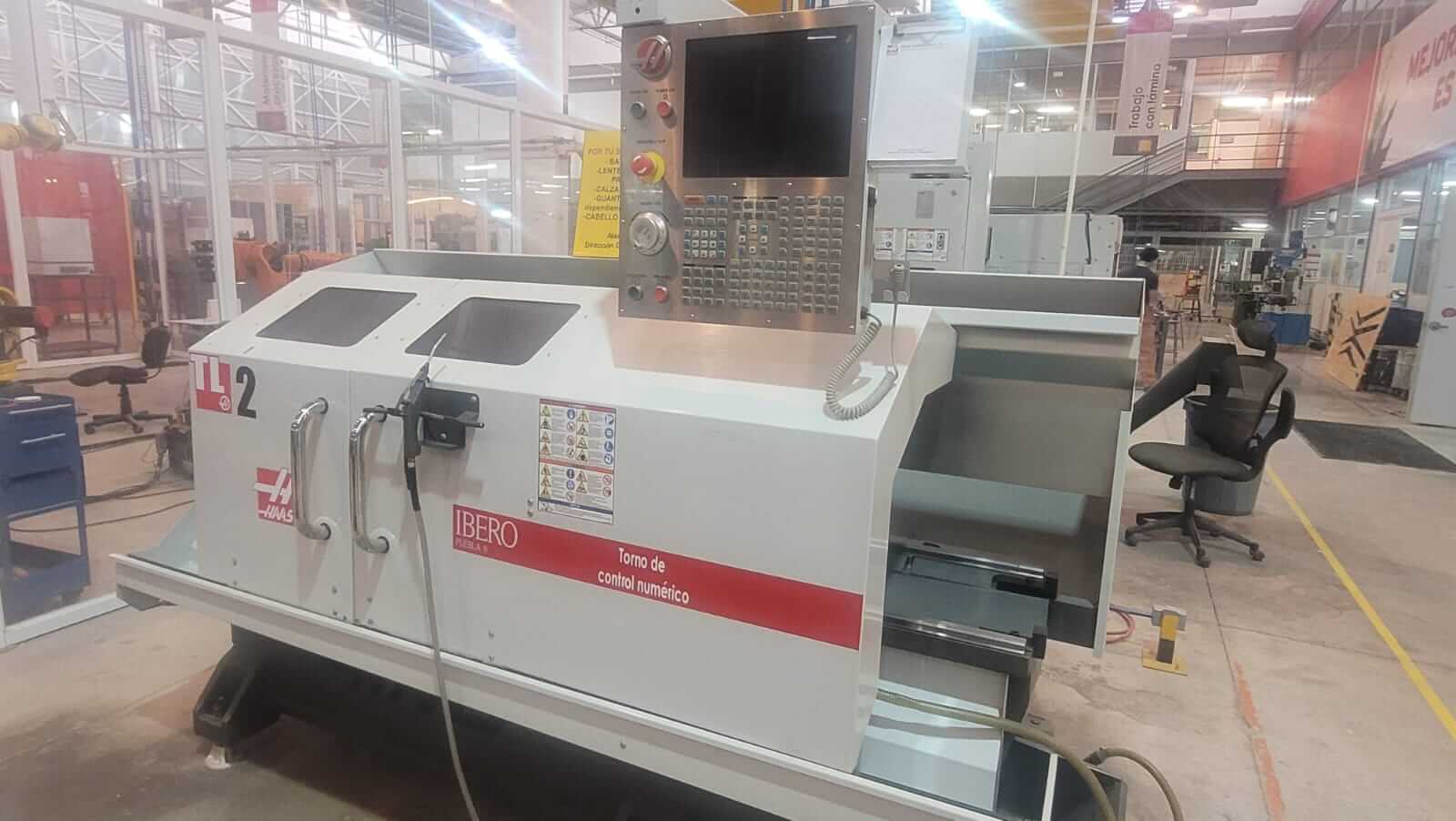
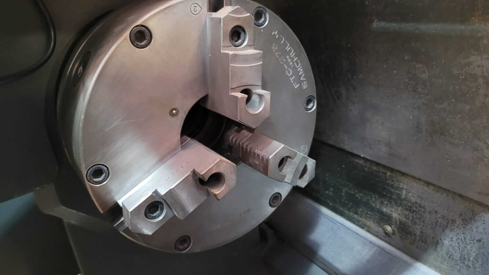
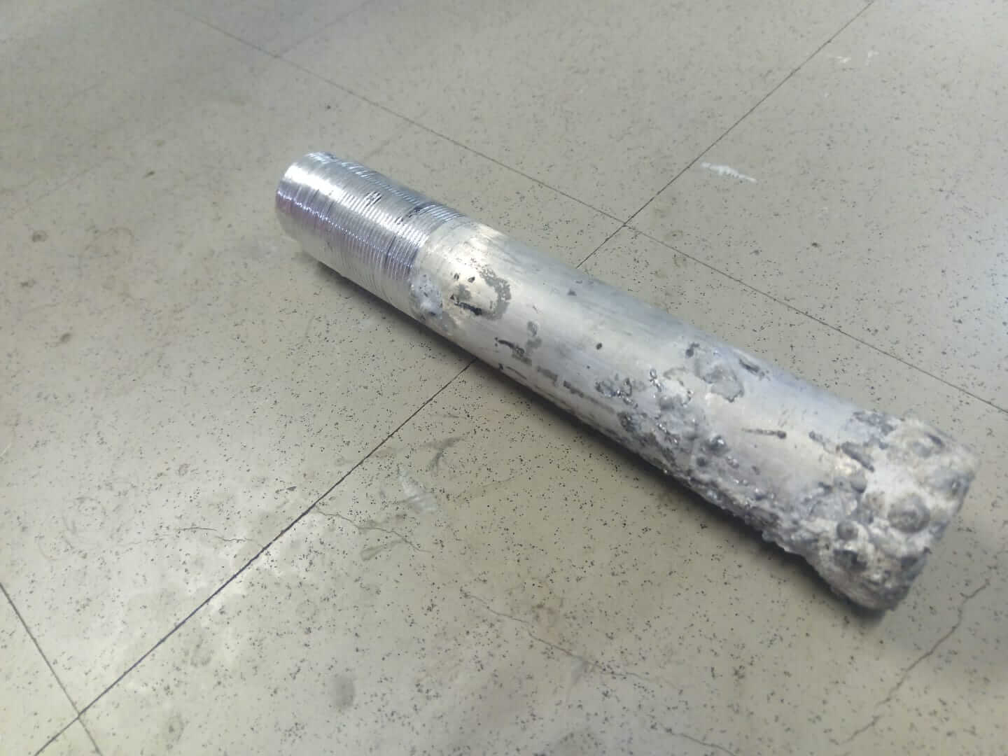
The next step was to machine the parts I needed — in this case, my aluminum tube, which required a diameter of 2.2 inches to fit both the reducer coupling and the tip of the pneumatic piston plunger.I had previously welded the tube, then I faced both ends and cut threads on one side. For the plunger tip, I took an aluminum cylinder, turned it on the lathe to shape the tip, then milled it, flattening two sides. In the resulting rectangular section, I drilled a hole to allow it to be secured from there. (all machining was on a CNC lathe except for the part of the milling bench)
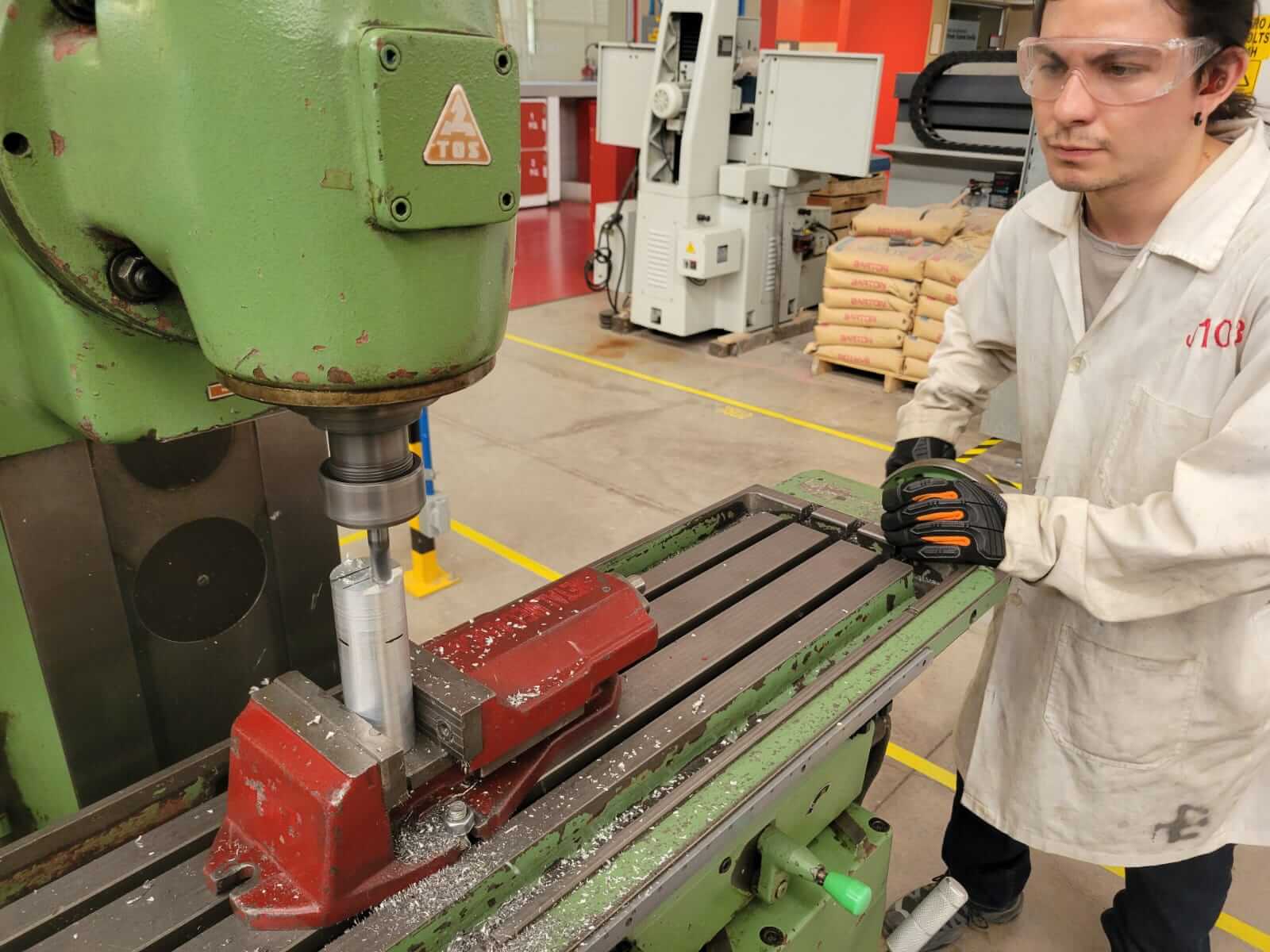
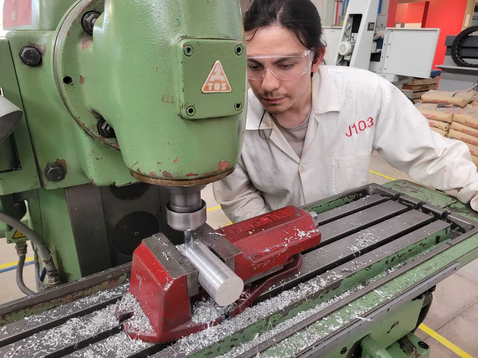
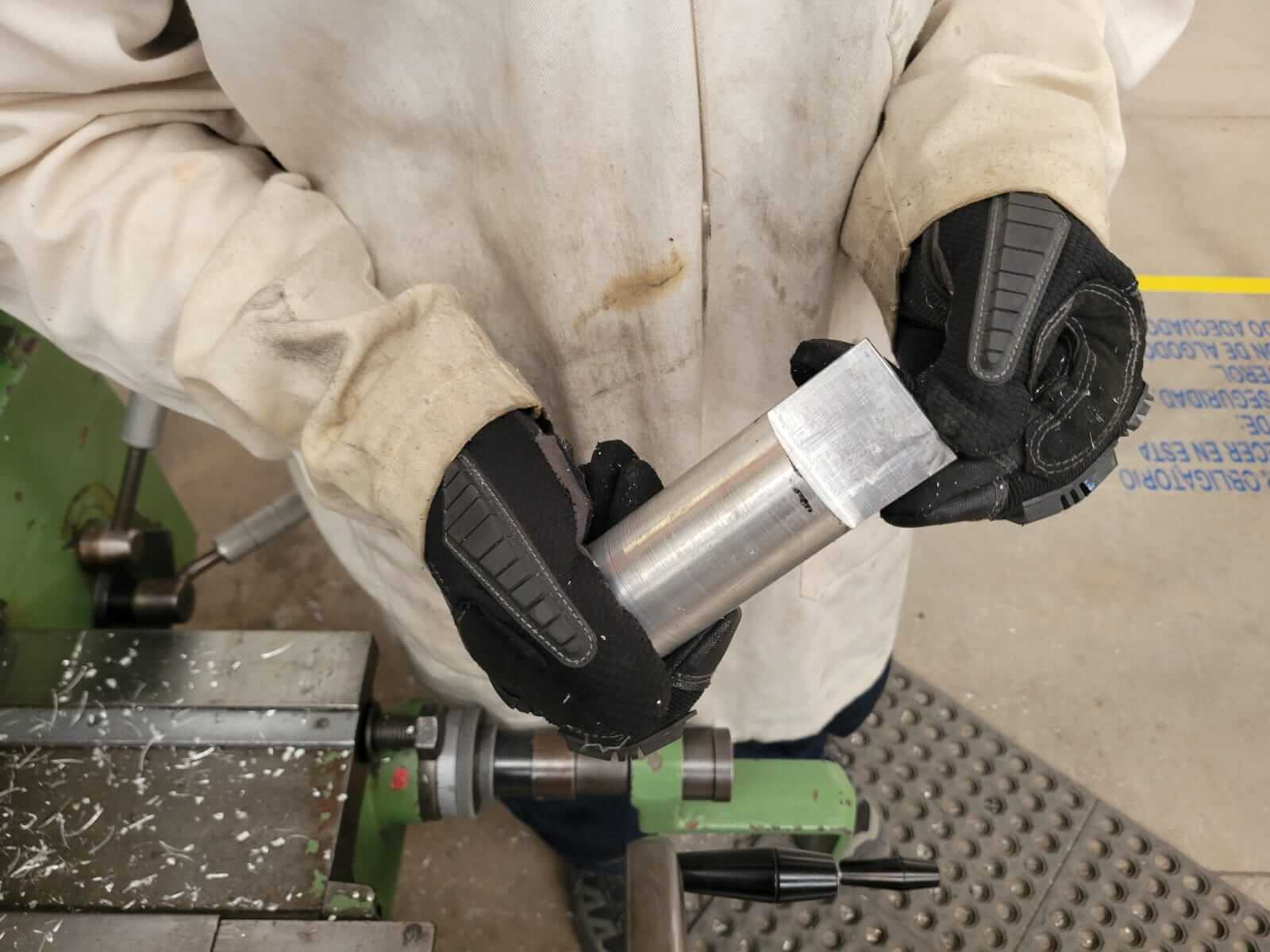
Unfortunately, I didn't take any photos of the CNC lathe process, but the steps to smooth the weld on my extrusion tube and to make the plunger were done using the CNC lathe.
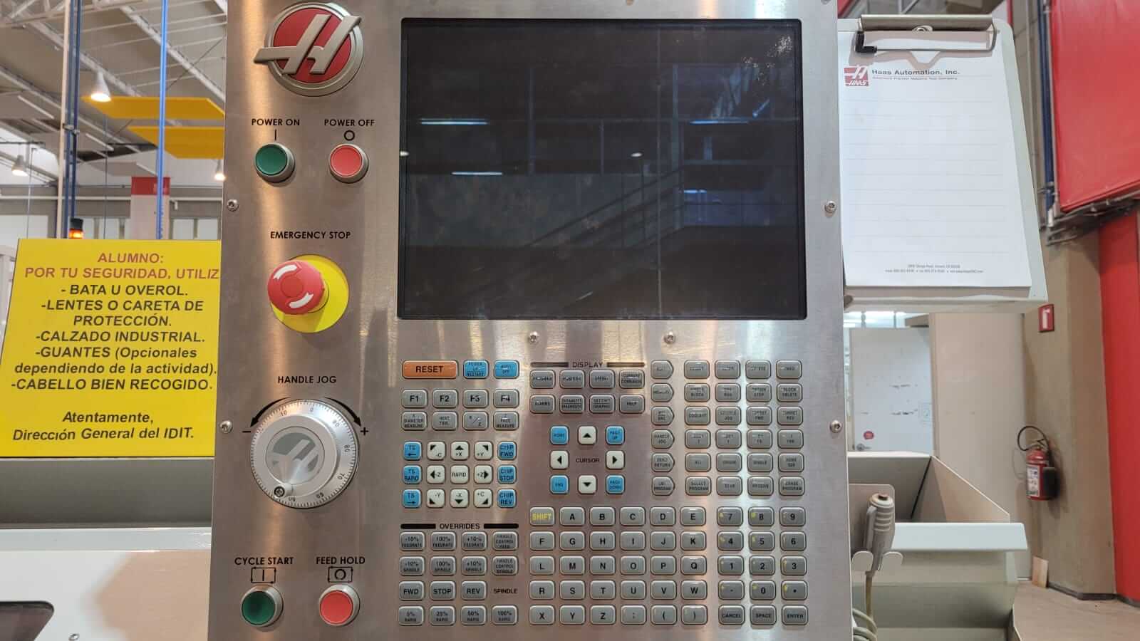
Always wear safety glasses and hearing protection. Make sure there are no loose objects on the machine. Do not place your hands near the machine while it is operating. Ensure that the emergency stop button (E-Stop) is visible and functional and verify that the spindle guard is in place.
Tool used: Diamond-shaped insert (DNMG), compatible DNMG tool holder, torque wrench to secure the insert, cylindrical raw stock (aluminum or steel).
Release the E-Stop button if it is activated, then select MEM or MDI mode. Perform the Home operation (referencing the Z and X axes), then load the program or manually write the G-code. Finally, place the material in the chuck and tighten it with moderate force. Use the touch setter or turret to set the tool offset for the Z and X axes.
I wasn't directly involved in the programming section, as this part was done by a university technician. However, I understand it was done in SolidWorks. I decided to replicate the lathe's operation in the same program. It's worth noting that I didn't do this part not because I couldn't, but because we aren't allowed to use the machine unsupervised. That said, here are some samples of the work, and the files are included in a zip file at the end.
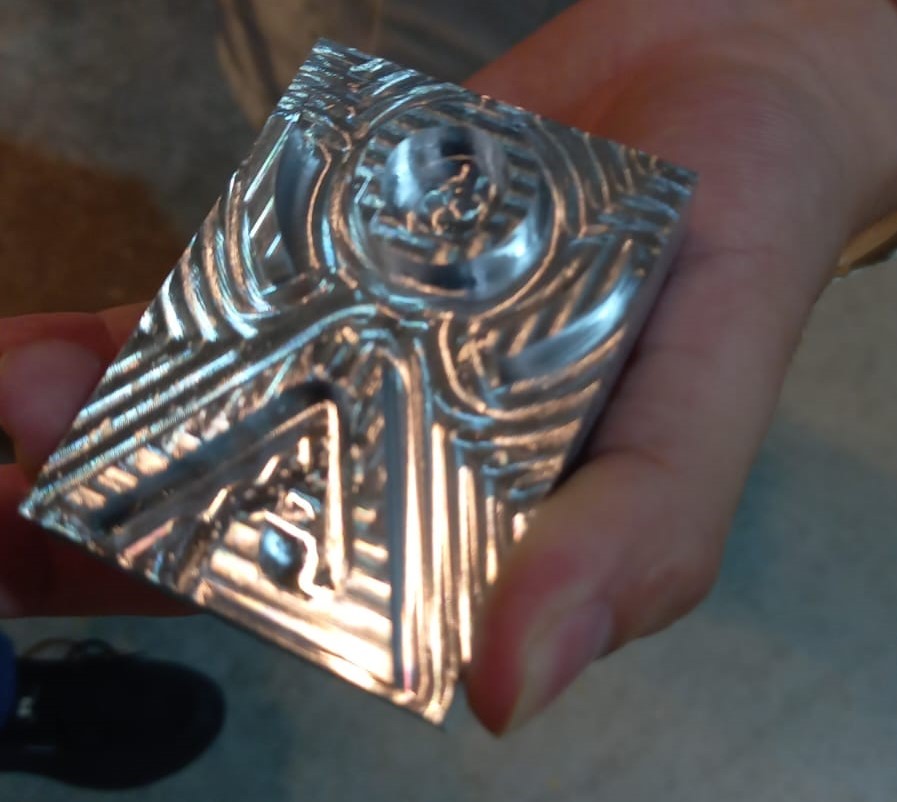
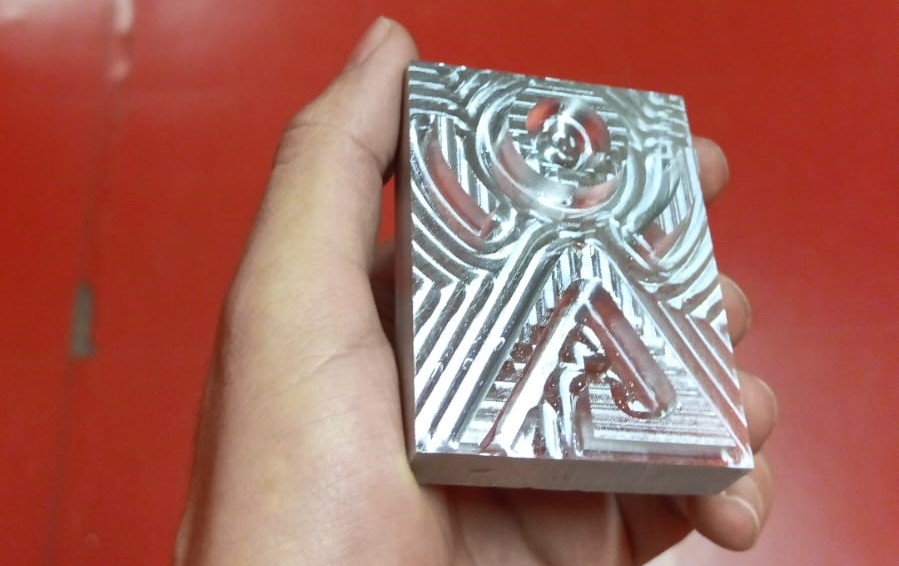
I tried to make a mold for one of my figures, but it didn't turn out quite right, so I didn't include it. However, here's a video showing the use of a CNC milling machine. The designs were made in Catia using the prismatic machining section. Here's the video.
The values and tools used were a 3mm diameter cutter, cutting speed of 250 m/min, RPM of 20,000, feed rate of 1000 mm/min
I didn't machine the other piece, as I realized it would be useless at this point, so I left it like that.
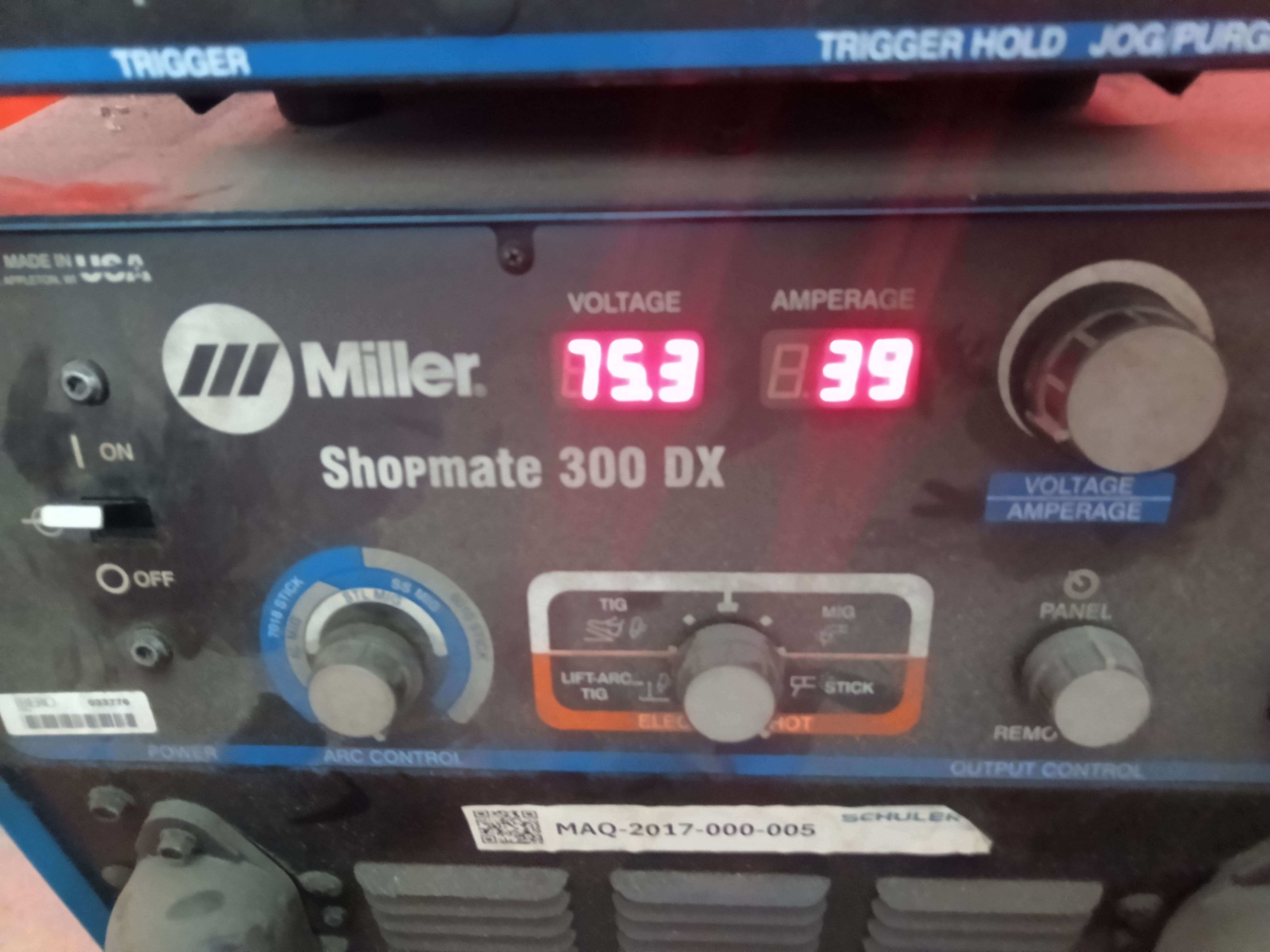
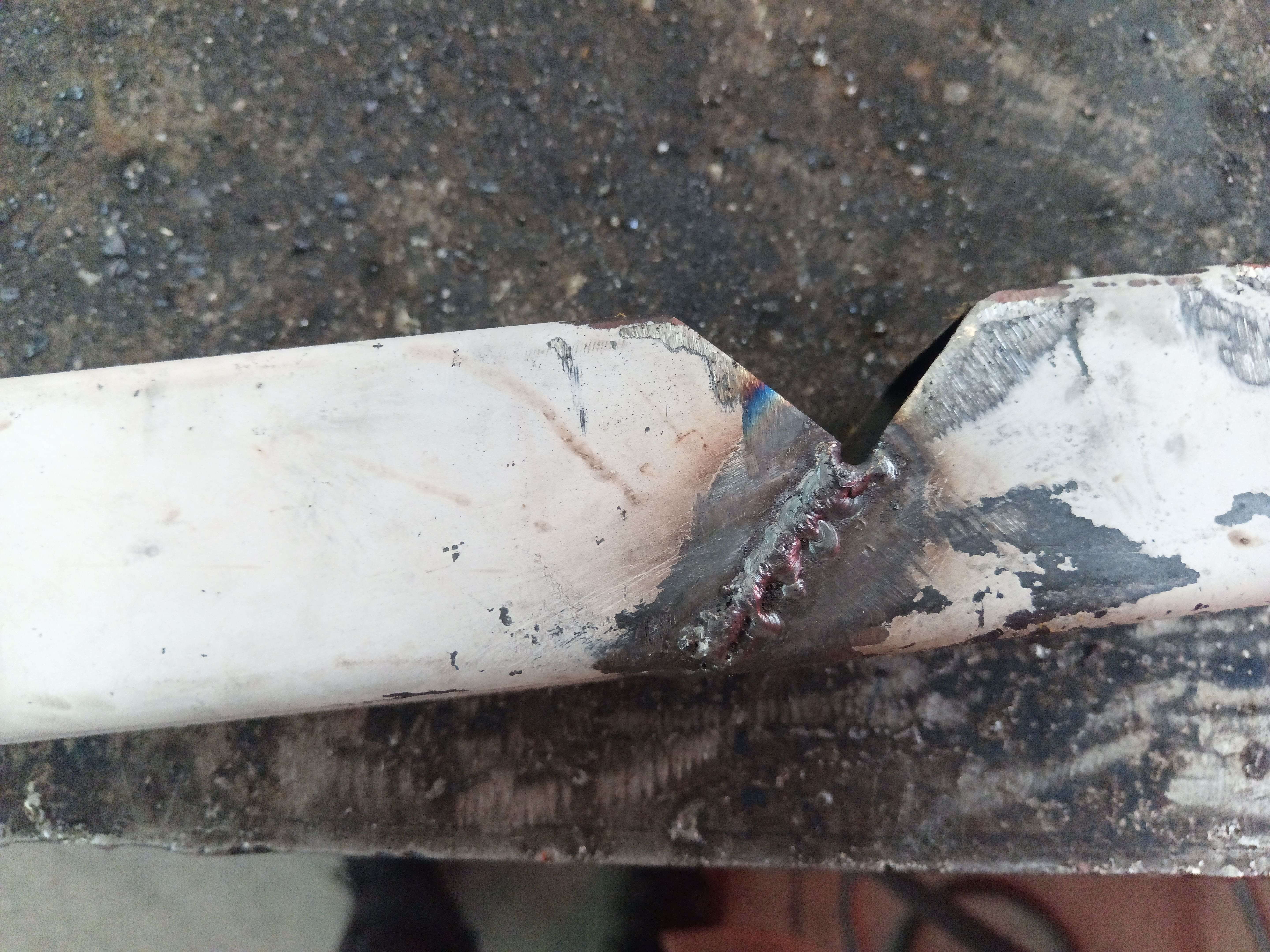
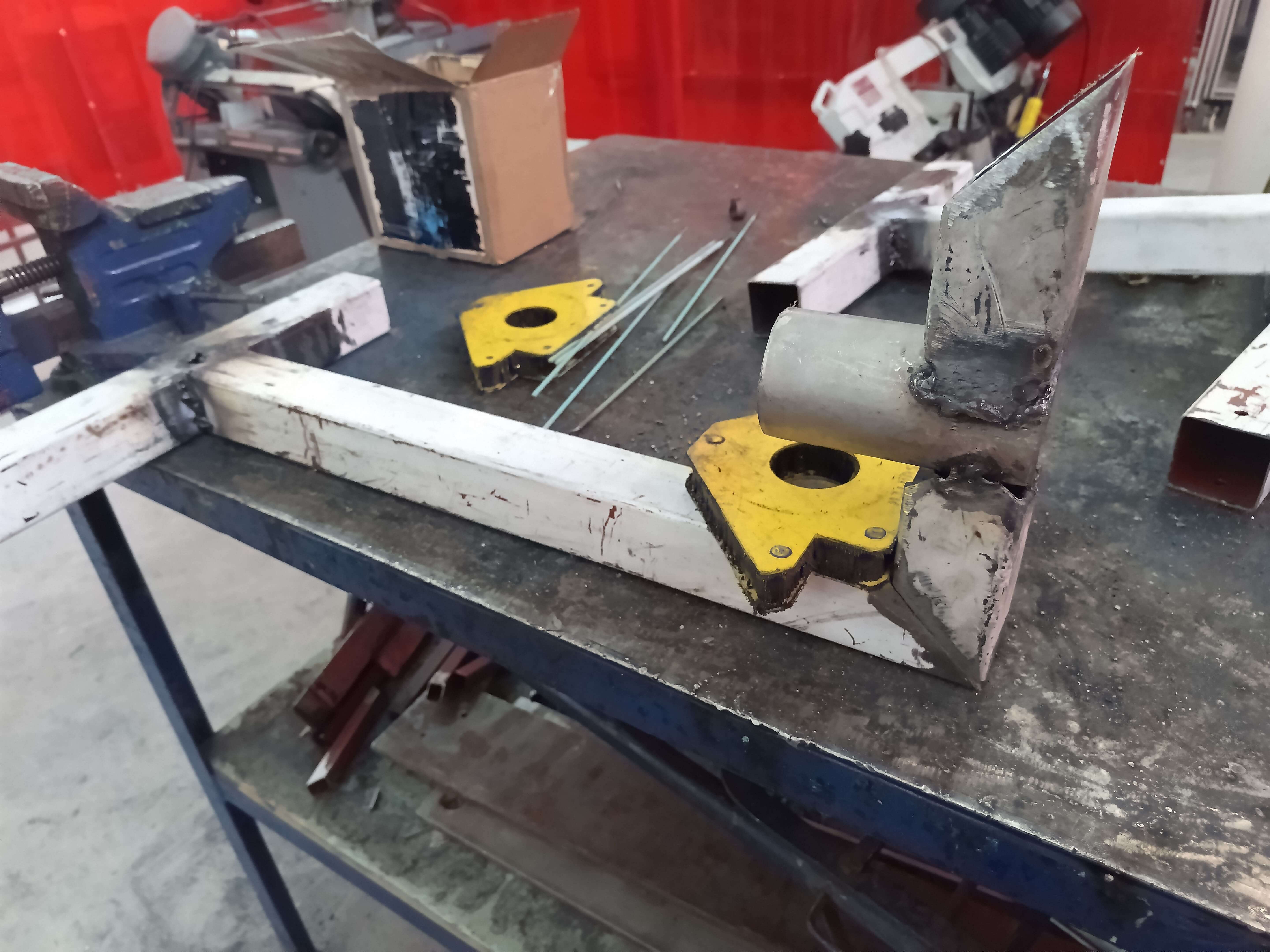
On the other hand, here's a photo of my attempts at welding aluminum on a tube.
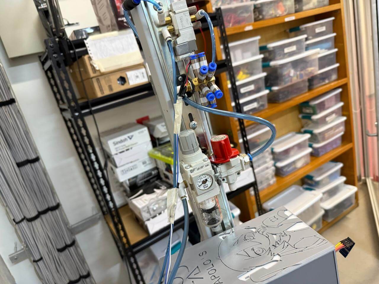
Next, I looked for a way to control the movement of my piston, which is fairly simple. It includes an air filter regulator that directs air to a distribution block (this isn't strictly necessary, but I chose to include it). From there, the air goes to a solenoid valve, which tells my piston (which, by the way, is double-acting) whether to move up or down.
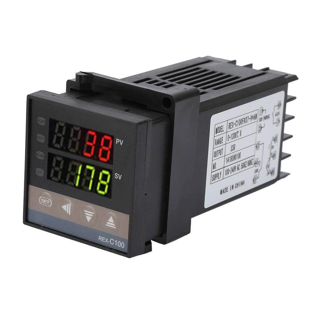
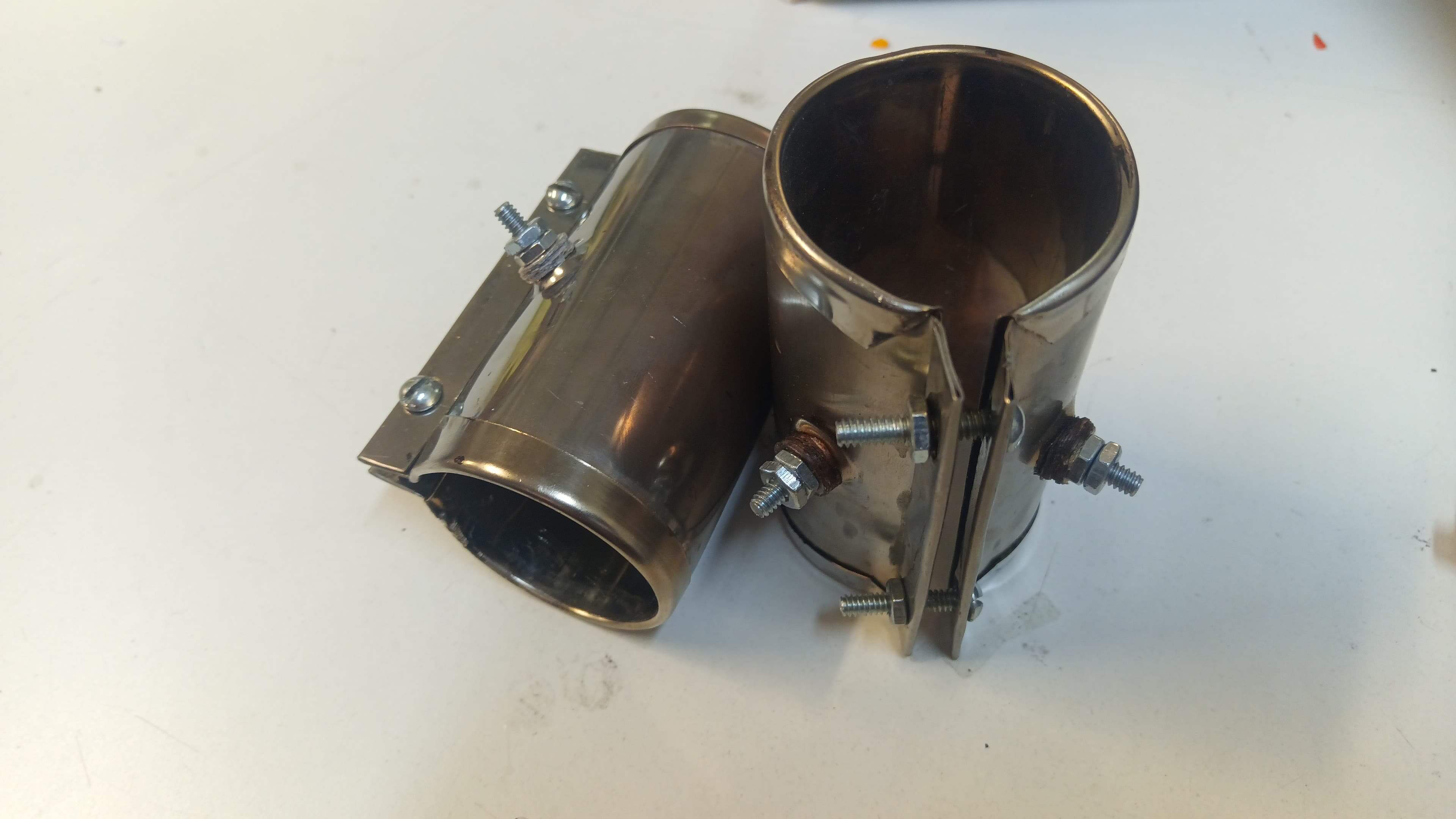
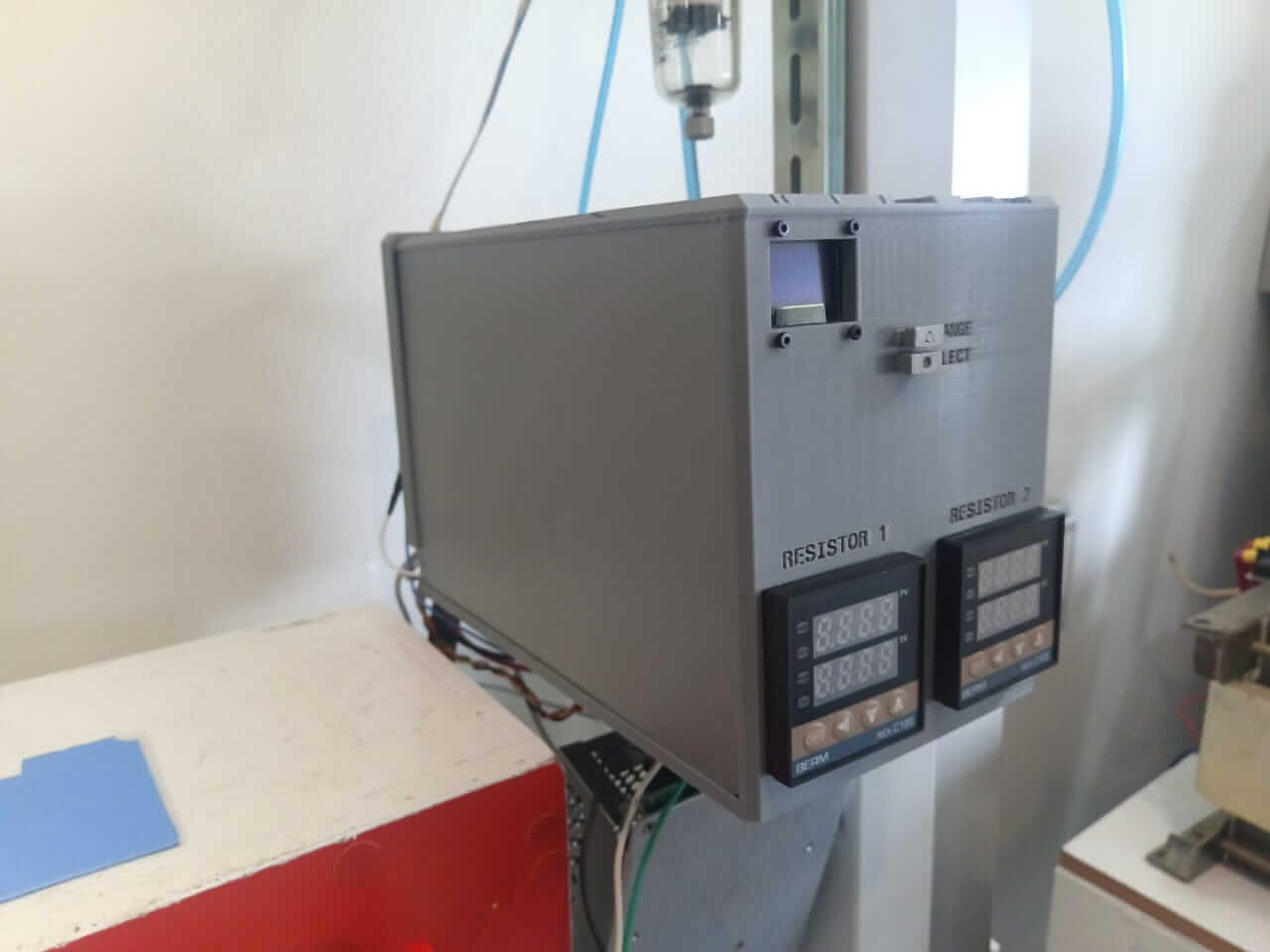
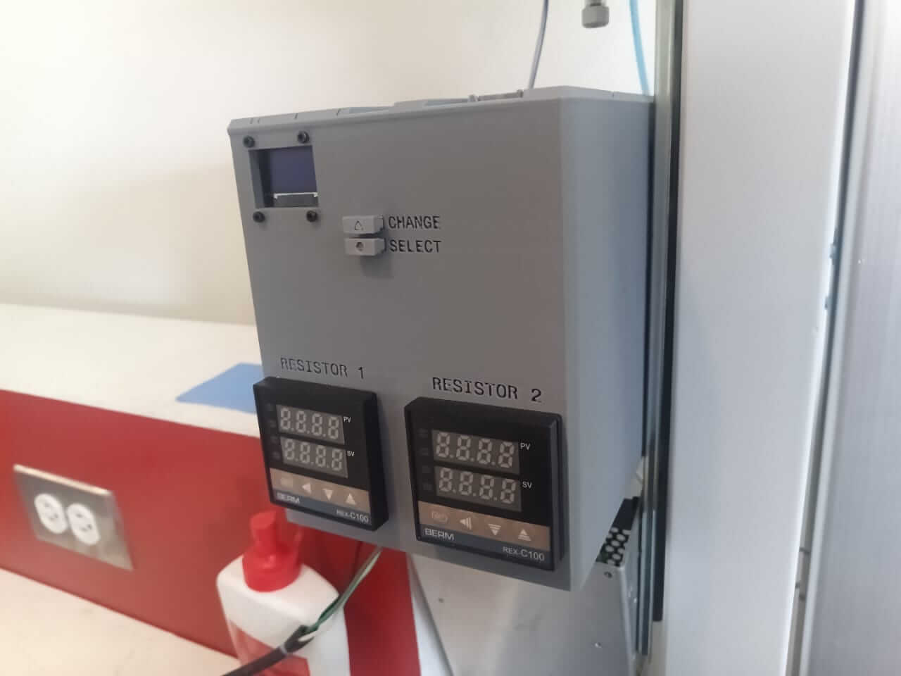
After that I did was to think about the power electronics — or more precisely, the PID temperature controllers, together with band heaters, which will be responsible for heating the plastic inside the metal tube.
This part was a bit more challenging for me since I have limited knowledge in the area. However, because the setup was quite simple, I didn't have major issues. What I did was connect a pair of band heaters, each to its own control module as indicated in the manual. I also got help from this YouTube video. Although I could have wired them in parallel to use a single control module, I preferred to give each one a separate temperature setting. Something I added was a digital control system to turn the heaters on or off whenever I want, using a pair of solid-state relays — but I'll show that part later in the control electronics section.
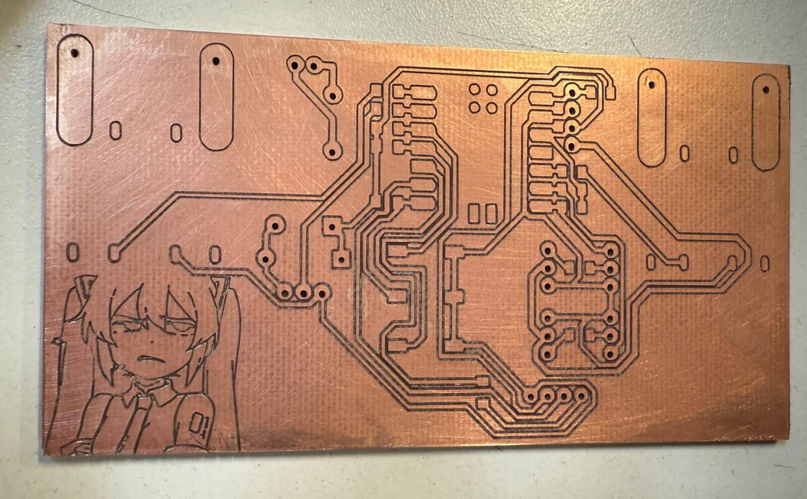
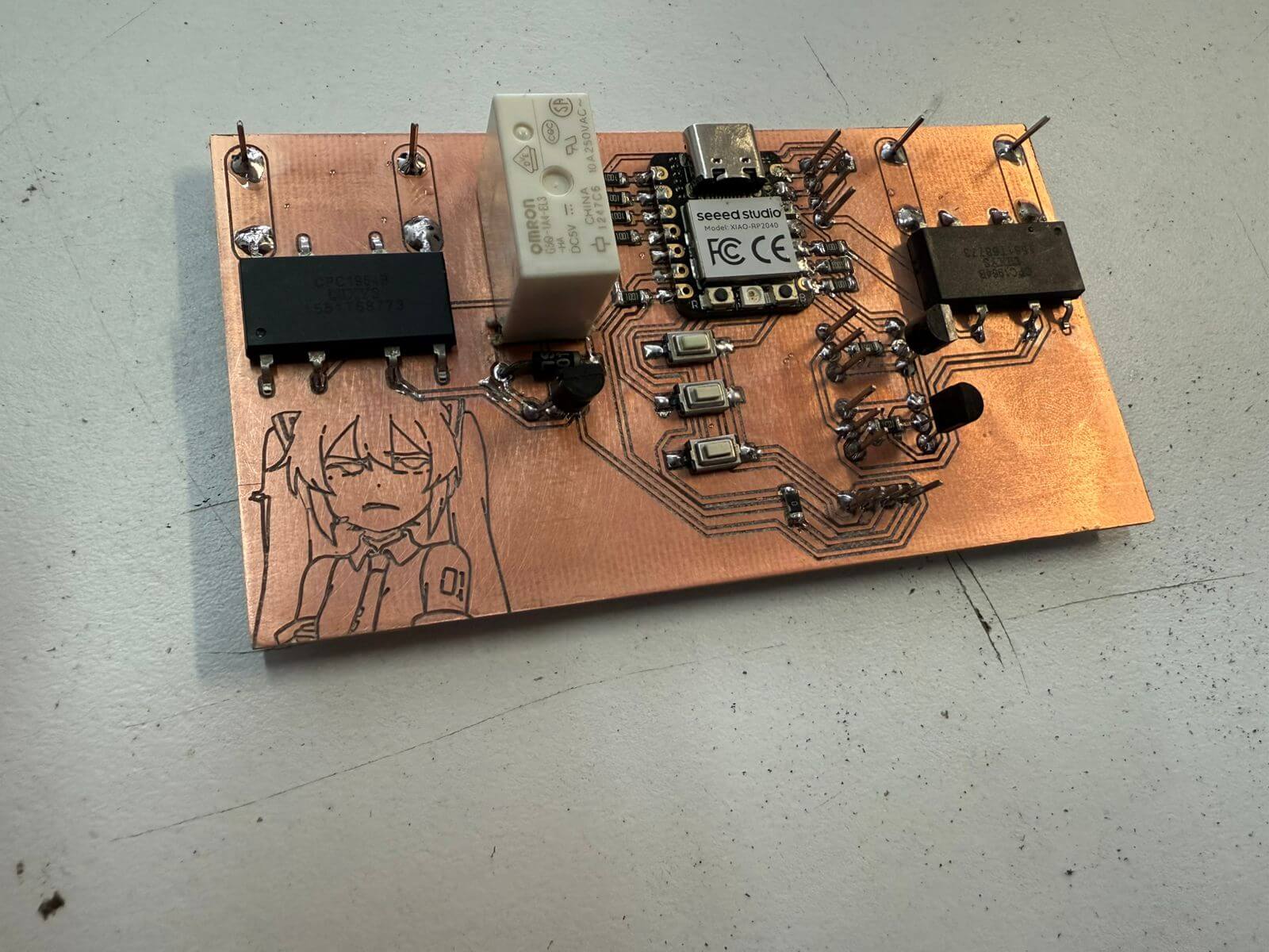
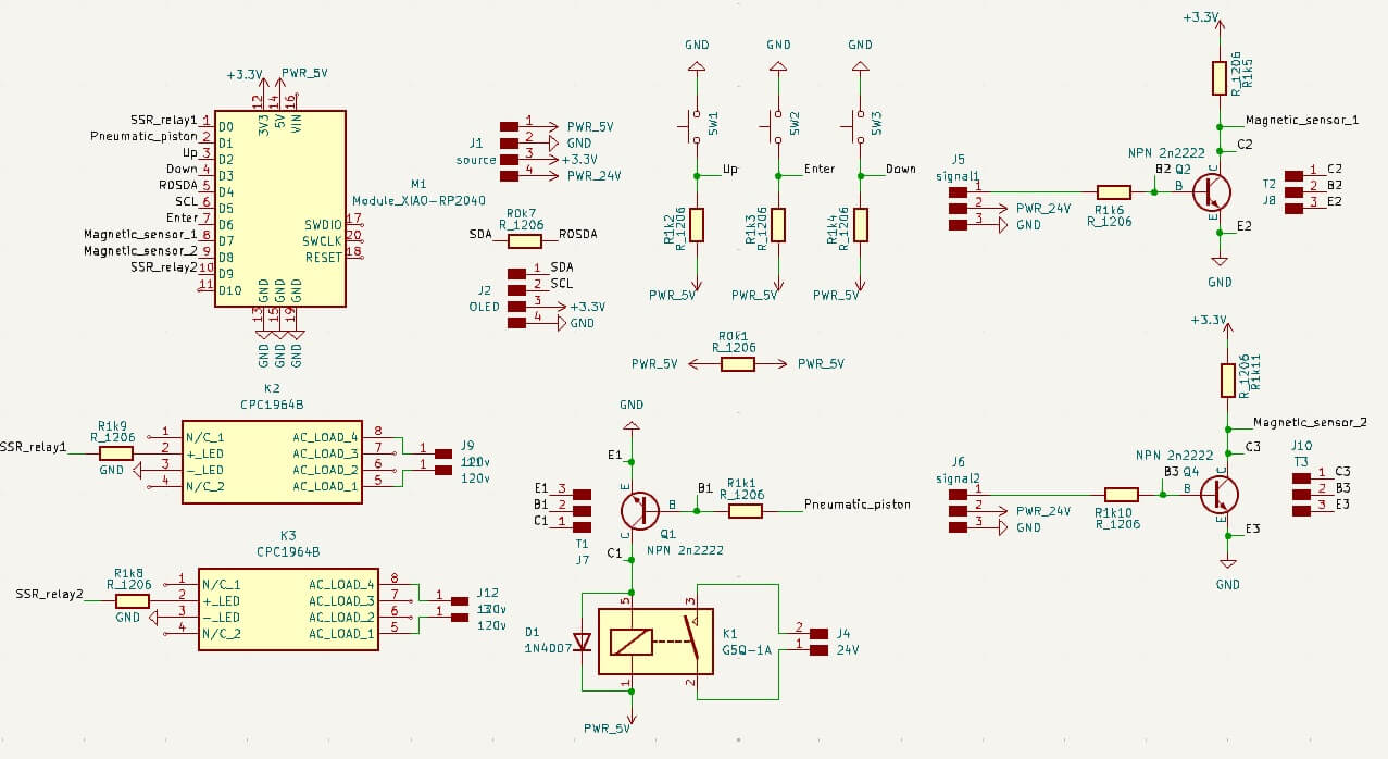
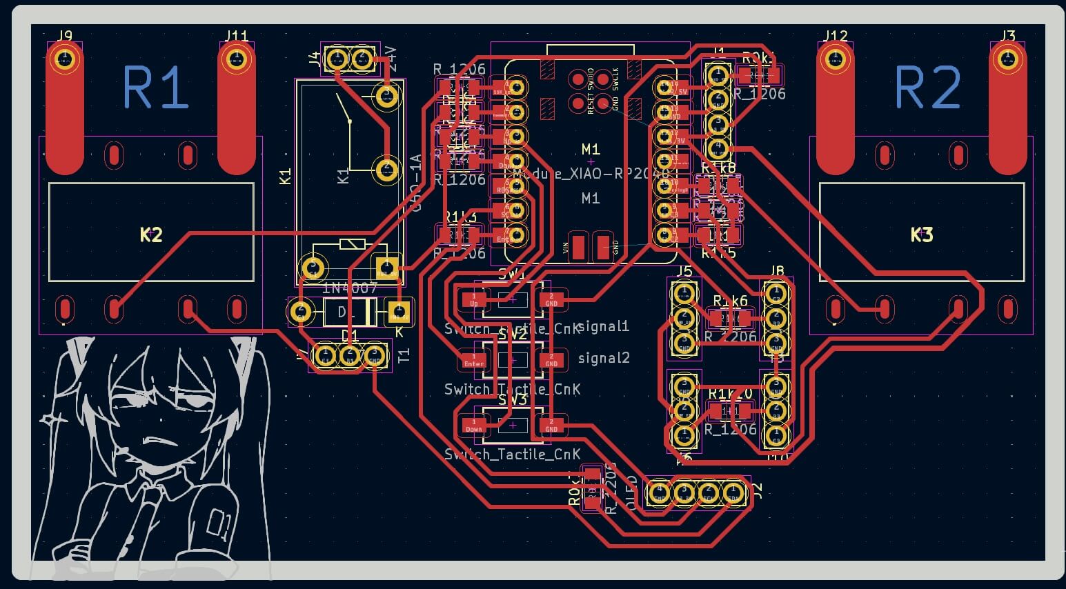
As for the electronics, I designed a custom board that includes a reprogrammable XIAO RP2040 microcontroller. Its functions include turning three relays on or off: one that controls the piston's movement, and two solid-state relays that turn the heaters on and off, one for each. It also receives signals from two magnetic sensors mounted on the piston to detect whether it is in the upper or lower position. Additionally, it features a small OLED screen that displays what is happening in the system in real time, along with a pair of buttons — one for selecting an option and the other for switching to the desired option. It's important to note that the temperature of the heating modules cannot be controlled from here, since the model I purchased cannot be reprogrammed or externally controlled via inputs, as it simply doesn't have them. Therefore, temperature must be set directly on the modules themselves — but I find this setup quite convenient.
The entire system has only two connections: one to AC power, which supplies everything — including my dual power supply (5V and 24V), the control board, and the heaters along with their control modules; and the second connection is for compressed air, which is required to operate the pneumatic piston.
My plate manufacturing methods are exactly the same as week 8
Here's my code:
// --- Libraries --- #include#include #include // --- OLED Display Configuration --- #define SCREEN_WIDTH 128 #define SCREEN_HEIGHT 64 #define OLED_RESET -1 #define SCREEN_ADDRESS 0x3C Adafruit_SSD1306 display(SCREEN_WIDTH, SCREEN_HEIGHT, &Wire, OLED_RESET); // --- Pin Definitions --- #define RELE_RESISTOR1_PIN D0 #define RELE_PISTON_PIN D1 #define RELE_RESISTOR2_PIN D9 #define BUTTON_UP D2 #define BUTTON_DOWN D3 #define BUTTON_SELECT D6 #define SENSOR_BEGIN_PIN D7 #define SENSOR_END_PIN D8 // --- System States --- bool resistor1 = false; bool piston = false; bool resistor2 = false; int selectedOption = 0; const int NUM_OPTIONS = 3; String options[NUM_OPTIONS] = { "Resistor 1", "Resistor 2", "Piston" }; int animationFrame = 0; unsigned long lastAnimationTime = 0; // --- Setup --- void setup() { Wire.begin(); // Initialize I2C display.begin(SSD1306_SWITCHCAPVCC, SCREEN_ADDRESS); display.clearDisplay(); showStartupScreen(); // Show logo and fake loading // Set relay pins as outputs and turn them off pinMode(RELE_RESISTOR1_PIN, OUTPUT); pinMode(RELE_PISTON_PIN, OUTPUT); pinMode(RELE_RESISTOR2_PIN, OUTPUT); digitalWrite(RELE_RESISTOR1_PIN, LOW); digitalWrite(RELE_PISTON_PIN, LOW); digitalWrite(RELE_RESISTOR2_PIN, LOW); // Configure button pins with internal pull-up resistors pinMode(BUTTON_UP, INPUT_PULLUP); pinMode(BUTTON_DOWN, INPUT_PULLUP); pinMode(BUTTON_SELECT, INPUT_PULLUP); // Configure sensor pins as inputs pinMode(SENSOR_BEGIN_PIN, INPUT); pinMode(SENSOR_END_PIN, INPUT); drawMenu(); // Initial screen } // --- Main Loop --- void loop() { static unsigned long lastDebounce = 0; if (millis() - lastDebounce > 200) { if (digitalRead(BUTTON_UP) == HIGH) { // Logic inverted selectedOption = (selectedOption - 1 + NUM_OPTIONS) % NUM_OPTIONS; lastDebounce = millis(); } else if (digitalRead(BUTTON_DOWN) == HIGH) { selectedOption = (selectedOption + 1) % NUM_OPTIONS; lastDebounce = millis(); } else if (digitalRead(BUTTON_SELECT) == HIGH) { switch (selectedOption) { case 0: resistor1 = !resistor1; digitalWrite(RELE_RESISTOR1_PIN, resistor1 ? HIGH : LOW); break; case 1: resistor2 = !resistor2; digitalWrite(RELE_RESISTOR2_PIN, resistor2 ? HIGH : LOW); break; case 2: piston = !piston; digitalWrite(RELE_PISTON_PIN, piston ? HIGH : LOW); break; } lastDebounce = millis(); } } // Handle animation frame updates if (millis() - lastAnimationTime > 150) { animationFrame = (animationFrame + 1) % 3; lastAnimationTime = millis(); } drawMenu(); delay(50); } // --- Startup Screen with Logo and Fake Loading Bar --- void showStartupScreen() { display.clearDisplay(); display.setTextSize(2); display.setTextColor(SSD1306_WHITE); display.setCursor(24, 0); display.println("Apolo's"); display.display(); delay(800); // Drawing a simple humanoid figure logo display.drawCircle(64, 28, 7, SSD1306_WHITE); // Head display.drawLine(48, 54, 64, 36, SSD1306_WHITE); // Left body display.drawLine(64, 36, 80, 54, SSD1306_WHITE); // Right body display.drawLine(54, 54, 74, 54, SSD1306_WHITE); // Base display.drawLine(64, 42, 64, 54, SSD1306_WHITE); // Center line display.drawLine(48, 40, 34, 28, SSD1306_WHITE); // Left arm display.drawLine(80, 40, 94, 28, SSD1306_WHITE); // Right arm display.display(); // Fake loading bar for (int i = 0; i <= 100; i += 10) { display.drawRect(14, 58, 100, 4, SSD1306_WHITE); // Frame display.fillRect(16, 60, i, 2, SSD1306_WHITE); // Progress display.display(); delay(180); } delay(300); display.clearDisplay(); display.display(); } // --- Menu Interface with Status and Animation --- void drawMenu() { display.clearDisplay(); display.setTextSize(1); display.setTextColor(SSD1306_WHITE); display.setCursor(0, 0); display.println("Control Interface"); for (int i = 0; i < NUM_OPTIONS; i++) { display.setCursor(0, 12 + i * 10); display.print(i == selectedOption ? "> " : " "); display.setCursor(10, 12 + i * 10); display.print(options[i]); display.setCursor(80, 12 + i * 10); bool state = (i == 0) ? resistor1 : (i == 1) ? resistor2 : piston; display.print(state ? "ON" : "OFF"); if (state) { int cx = 110; int cy = 14 + i * 10; switch (animationFrame) { case 0: display.drawCircle(cx, cy, 2, SSD1306_WHITE); break; case 1: display.fillCircle(cx, cy, 2, SSD1306_WHITE); break; case 2: display.drawCircle(cx, cy, 2, SSD1306_WHITE); display.drawPixel(cx, cy, SSD1306_BLACK); break; } } } // Display sensor indicators using filled or hollow circles display.setCursor(0, 42); display.print("Begin: "); if (digitalRead(SENSOR_BEGIN_PIN) == LOW) display.fillCircle(60, 44, 3, SSD1306_WHITE); // Active else display.drawCircle(60, 44, 3, SSD1306_WHITE); // Inactive display.setCursor(0, 52); display.print("End: "); if (digitalRead(SENSOR_END_PIN) == LOW) display.fillCircle(60, 54, 3, SSD1306_WHITE); else display.drawCircle(60, 54, 3, SSD1306_WHITE); display.display(); }
This section defines the configuration for the OLED display. The width and height are set to 128x64 pixels. The reset pin is not used, hence it's set to -1. The address 0x3C is the default I²C address of most SSD1306 modules. An instance of the display is created with these settings.
#define SCREEN_WIDTH 128
#define SCREEN_HEIGHT 64
#define OLED_RESET    -1
#define SCREEN_ADDRESS 0x3C
Adafruit_SSD1306 display(SCREEN_WIDTH, SCREEN_HEIGHT, &Wire, OLED_RESET);
Here, all digital pin assignments are declared using #define to simplify the rest of the code. There are three relays, three buttons, and two sensor inputs. The names clarify each pin’s function: relays for controlling components, buttons for navigating the menu, and sensors for detecting conditions.
#define RELE_RESISTOR1_PIN D0
#define RELE_PISTON_PIN    D1
#define RELE_RESISTOR2_PIN D9

#define BUTTON_UP          D2
#define BUTTON_DOWN        D3
#define BUTTON_SELECT      D6

#define SENSOR_BEGIN_PIN   D7
#define SENSOR_END_PIN     D8
This block initializes the program's state. Each output (resistor1, resistor2, piston) has a boolean variable to store whether it's ON or OFF. The selectedOption keeps track of the current menu item. animationFrame and lastAnimationTime are used to animate an icon when a relay is active.
bool resistor1 = false;
bool piston = false;
bool resistor2 = false;
int selectedOption = 0;
const int NUM_OPTIONS = 3;
String options[NUM_OPTIONS] = { "Resistor 1", "Resistor 2", "Piston" };

int animationFrame = 0;
unsigned long lastAnimationTime = 0;
In the setup() function, the I²C bus and the OLED display are initialized. The relays are configured as outputs and turned off. The buttons are configured with INPUT_PULLUP so they read HIGH by default and LOW when pressed. Sensor pins are set as inputs. Finally, the startup screen is shown and the menu is drawn.
void setup() {
  Wire.begin();
  display.begin(SSD1306_SWITCHCAPVCC, SCREEN_ADDRESS);
  display.clearDisplay();
  showStartupScreen();

  pinMode(RELE_RESISTOR1_PIN, OUTPUT);
  pinMode(RELE_PISTON_PIN, OUTPUT);
  pinMode(RELE_RESISTOR2_PIN, OUTPUT);

  digitalWrite(RELE_RESISTOR1_PIN, LOW);
  digitalWrite(RELE_PISTON_PIN, LOW);
  digitalWrite(RELE_RESISTOR2_PIN, LOW);

  pinMode(BUTTON_UP, INPUT_PULLUP);
  pinMode(BUTTON_DOWN, INPUT_PULLUP);
  pinMode(BUTTON_SELECT, INPUT_PULLUP);

  pinMode(SENSOR_BEGIN_PIN, INPUT);
  pinMode(SENSOR_END_PIN, INPUT);

  drawMenu();
}
The loop() function handles button input and relay toggling. A debounce delay of 200 ms prevents multiple detections from a single press. If a button is pressed (now using inverted logic: HIGH when pressed), it updates the selection or toggles the corresponding relay. Animation frames are updated every 150 ms to show activity next to an active device. The menu is refreshed constantly.
void loop() {
  static unsigned long lastDebounce = 0;
  if (millis() - lastDebounce > 200) {
    if (digitalRead(BUTTON_UP) == HIGH) {
      selectedOption = (selectedOption - 1 + NUM_OPTIONS) % NUM_OPTIONS;
      lastDebounce = millis();
    } else if (digitalRead(BUTTON_DOWN) == HIGH) {
      selectedOption = (selectedOption + 1) % NUM_OPTIONS;
      lastDebounce = millis();
    } else if (digitalRead(BUTTON_SELECT) == HIGH) {
      switch (selectedOption) {
        case 0: resistor1 = !resistor1;
                digitalWrite(RELE_RESISTOR1_PIN, resistor1 ? HIGH : LOW);
                break;
        case 1: resistor2 = !resistor2;
                digitalWrite(RELE_RESISTOR2_PIN, resistor2 ? HIGH : LOW);
                break;
        case 2: piston = !piston;
                digitalWrite(RELE_PISTON_PIN, piston ? HIGH : LOW);
                break;
      }
      lastDebounce = millis();
    }
  }

  if (millis() - lastAnimationTime > 150) {
    animationFrame = (animationFrame + 1) % 3;
    lastAnimationTime = millis();
  }

  drawMenu();
  delay(50);
}
This function shows a startup screen when the system powers on. It displays the title “Apolo’s” and a simple stick-figure logo using shapes. Then, a fake loading bar animates from 0% to 100% using a loop. This screen is purely cosmetic, to give the project a polished feel.
void showStartupScreen() {
  display.clearDisplay();
  display.setTextSize(2);
  display.setTextColor(SSD1306_WHITE);
  display.setCursor(24, 0);
  display.println("Apolo's");
  display.display();
  delay(800);

  display.drawCircle(64, 28, 7, SSD1306_WHITE);
  display.drawLine(48, 54, 64, 36, SSD1306_WHITE);
  display.drawLine(64, 36, 80, 54, SSD1306_WHITE);
  display.drawLine(54, 54, 74, 54, SSD1306_WHITE);
  display.drawLine(64, 42, 64, 54, SSD1306_WHITE);
  display.drawLine(48, 40, 34, 28, SSD1306_WHITE);
  display.drawLine(80, 40, 94, 28, SSD1306_WHITE);

  display.display();
  for (int i = 0; i <= 100; i += 10) {
    display.drawRect(14, 58, 100, 4, SSD1306_WHITE);
    display.fillRect(16, 60, i, 2, SSD1306_WHITE);
    display.display();
    delay(180);
  }

  delay(300);
  display.clearDisplay();
  display.display();
}
This function redraws the user interface. It prints the current menu title, each option (with a selection indicator), and their current ON/OFF state. If a device is ON, a small animated icon appears beside it using circles. Below the options, the current state of the Begin and End sensors is shown using filled or empty circles, giving visual feedback in real time.
void drawMenu() {
  display.clearDisplay();
  display.setTextSize(1);
  display.setTextColor(SSD1306_WHITE);
  display.setCursor(0, 0);
  display.println("Control Interface");

  for (int i = 0; i < NUM_OPTIONS; i++) {
    display.setCursor(0, 12 + i * 10);
    display.print(i == selectedOption ? "> " : "  ");
    display.setCursor(10, 12 + i * 10);
    display.print(options[i]);
    display.setCursor(80, 12 + i * 10);

    bool state = (i == 0) ? resistor1 :
                 (i == 1) ? resistor2 :
                            piston;
    display.print(state ? "ON" : "OFF");

    if (state) {
      int cx = 110;
      int cy = 14 + i * 10;
      switch (animationFrame) {
        case 0: display.drawCircle(cx, cy, 2, SSD1306_WHITE); break;
        case 1: display.fillCircle(cx, cy, 2, SSD1306_WHITE); break;
        case 2:
          display.drawCircle(cx, cy, 2, SSD1306_WHITE);
          display.drawPixel(cx, cy, SSD1306_BLACK); break;
      }
    }
  }

  display.setCursor(0, 42);
  display.print("Begin: ");
  if (digitalRead(SENSOR_BEGIN_PIN) == LOW)
    display.fillCircle(60, 44, 3, SSD1306_WHITE);
  else
    display.drawCircle(60, 44, 3, SSD1306_WHITE);

  display.setCursor(0, 52);
  display.print("End: ");
  if (digitalRead(SENSOR_END_PIN) == LOW)
    display.fillCircle(60, 54, 3, SSD1306_WHITE);
  else
    display.drawCircle(60, 54, 3, SSD1306_WHITE);

  display.display();
}
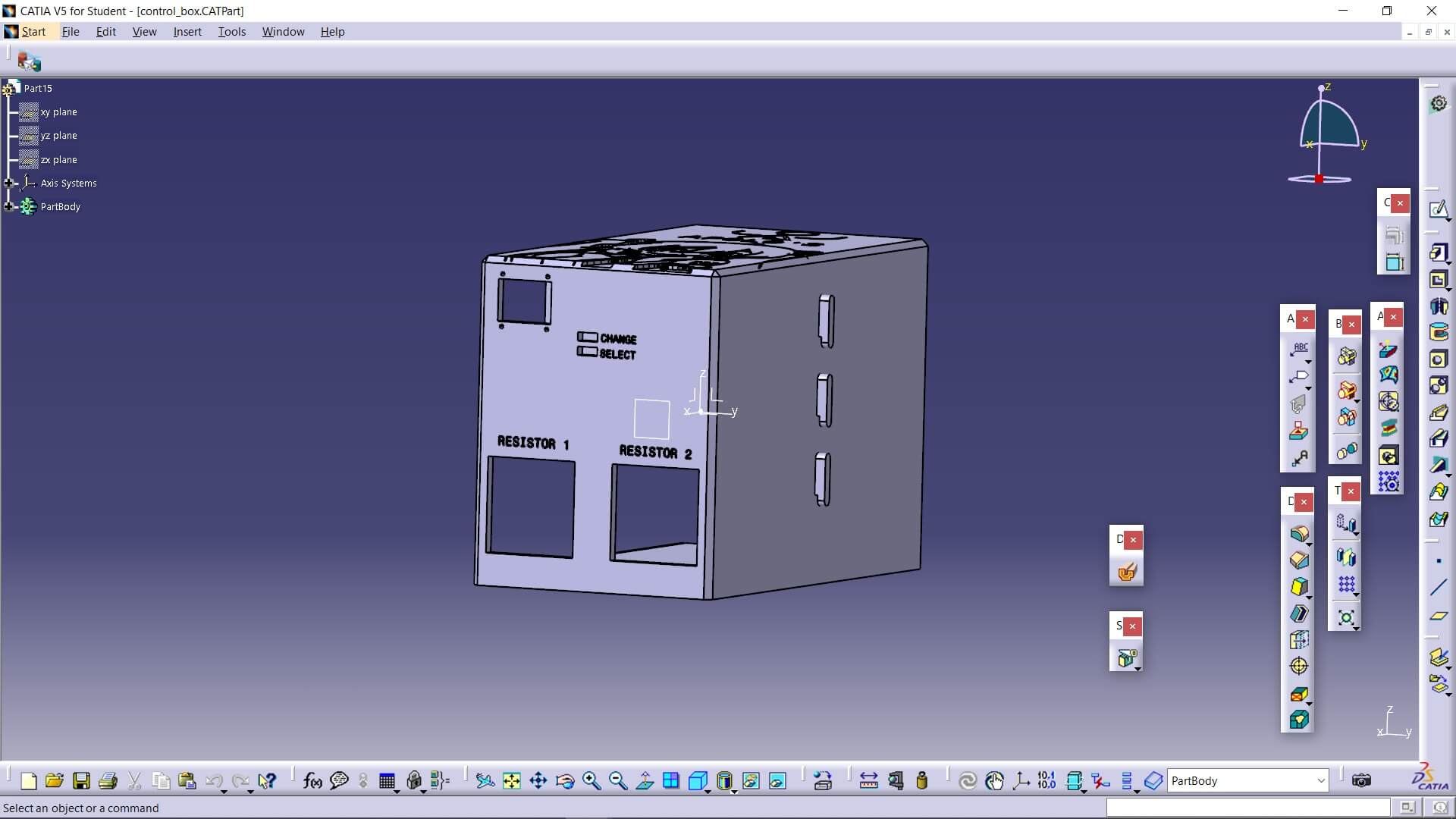
To keep all my cables and circuits organized, I made a box consisting of three parts: the main box, a sliding side cover, a rear cover and a pair of buttons. Everything was 3D printed—here are some pictures.
If you want to know all the parameters I used to print my box, you can look for it on my Week 5, where I show how I 3D print some pieces and his parameters which are exactly the same as the ones I used to print all with PLA
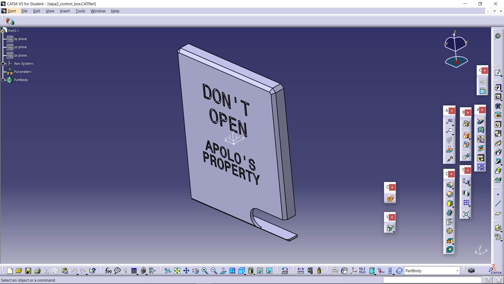
On the other hand, my mold was also 3D printed, but you can see the process for that in my Week 13.
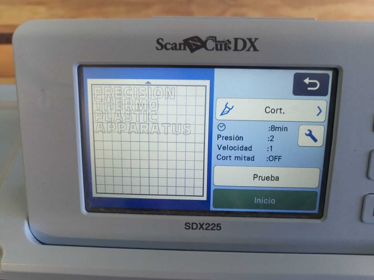
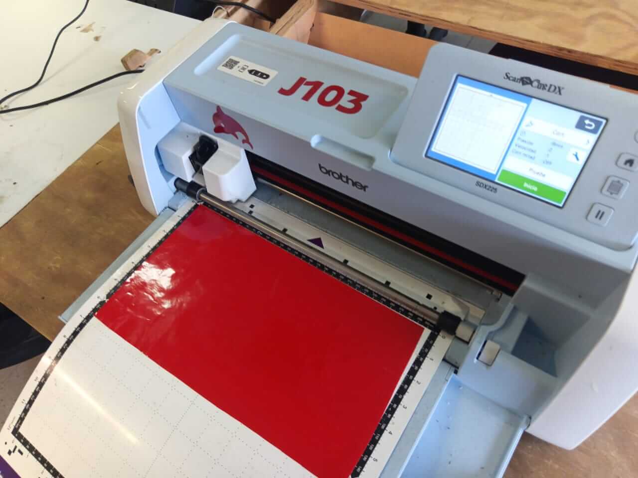
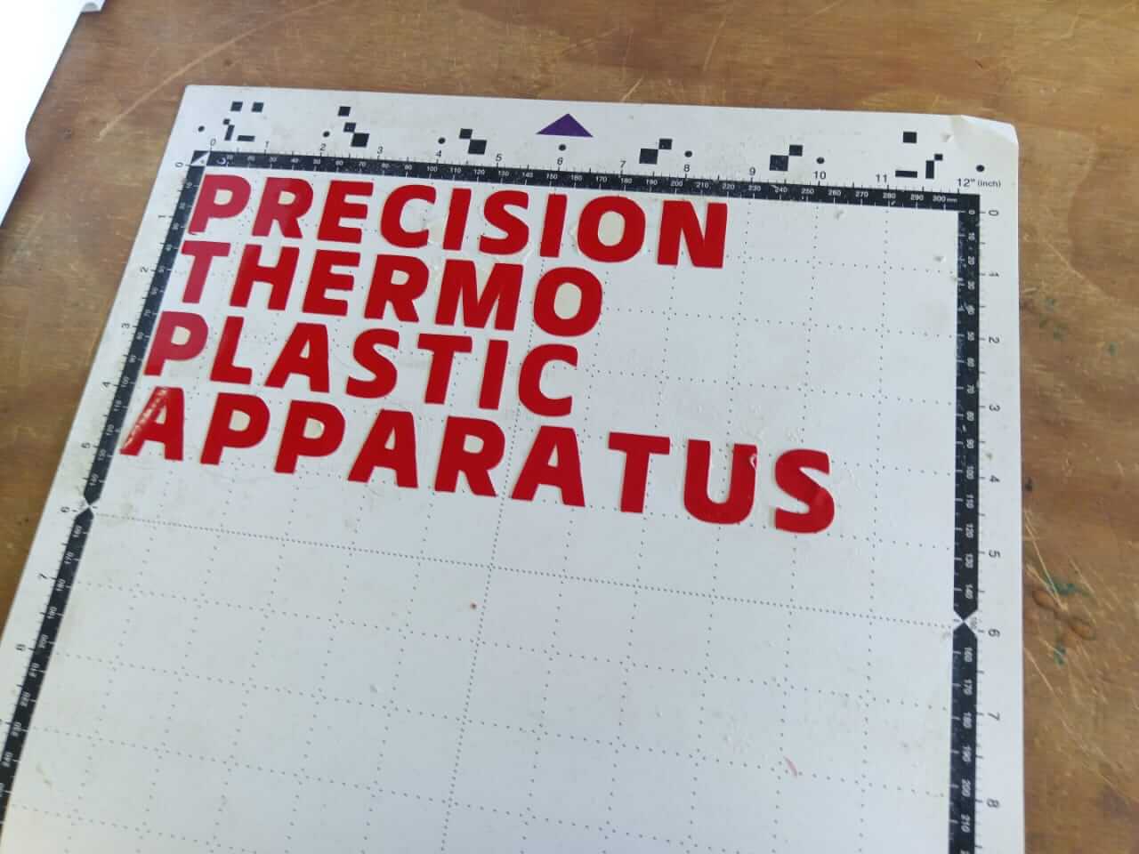
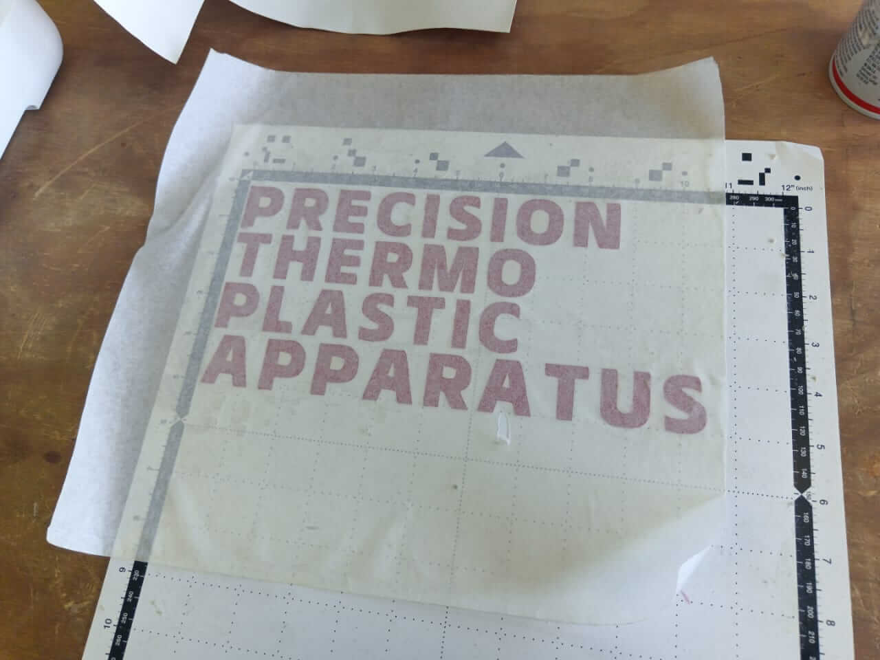
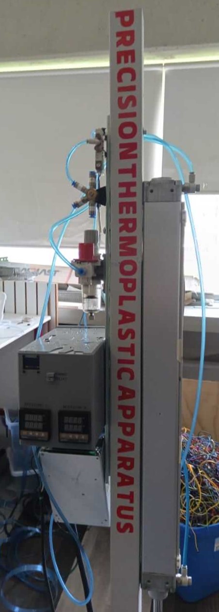
To complete the requirements for my machine in order to graduate, I made a vinyl cut as shown in the following images. It's worth noting that the entire process was carried out in the same way as in my Week 3:
To operate my machine, certain precautions must be taken. You only need to be careful with two things: the high temperature of the heaters and the piston, as the latter can break your hand if not handled properly. Now, using the machine is very simple. Set the desired temperature on the control modules, and from the interface, use the buttons to navigate and turn on the heaters you want. After approximately 15 minutes (in the case of PLA), the material can be extruded into the mold placed below the machine by deactivating the pneumatic control relay of the piston.
| Material | Quantity | Unit Cost (USD) |
|---|---|---|
| Xiaorp2040 | 1 | $7.06 |
| Push button | 3 | $0.09 |
| Transistor 2n2222 | 3 | $0.88 |
| Relay G5Q-1A4-EL3 | 1 | $0.59 |
| Diode 1N4007 | 1 | $0.24 |
| 1kΩ Resistor | 9 | $0.18 |
| OLED Display 0.96 inch | 1 | $2.94 |
| Magnetic Sensor D-M9P A | 2 | $7.06 |
| Band Heater 500W 120V | 4 | $25.88 |
| PID Temperature Controller REX-C100 | 2 | $18.41 |
| SSR Relay CPC1964B | 2 | $4.71 |
| Dual voltage source 24 and 5 volts | 2 | $20 |
| Material | Quantity | Cost (USD) |
|---|---|---|
| Pneumatic piston DZH-40-600-PPV-A | 1 | 260 |
| Aluminum tube 2" | 1m | $20.59 |
| Aluminum cylinder 2" | 50 cm | $23.53 |
| Steel flat bar | 12 cm | 2.5 |
| Steel tube 2" | 12 cm | 5 |
| Pneumatic hose | 1 m | 3 |
| Regulator filter AW20 F01E-B | 1 | 105 |
| SAI4-2050 - solenoid valve 3/2 monostable NC | 1 | 15.75 |
| SAI4-2092 distributor block | 1 | 15.75 |
| Metal bell coupling reducer 2" to 1" | 1 | 15.75 |
| 1" metal plug | 1 | 5 |
| Material | Quantity | Cost (USD) |
|---|---|---|
| Steel profile 3mm | 3.10 m | 31.5 |
Files for the plunger turning process
This ones were downloaded from this website
This is intended to be used by students or people in general with a slightly advanced knowledge of 3D printing or plastics