Week 11 Embedded Networking and Communications
communicating microcontrollers with each other
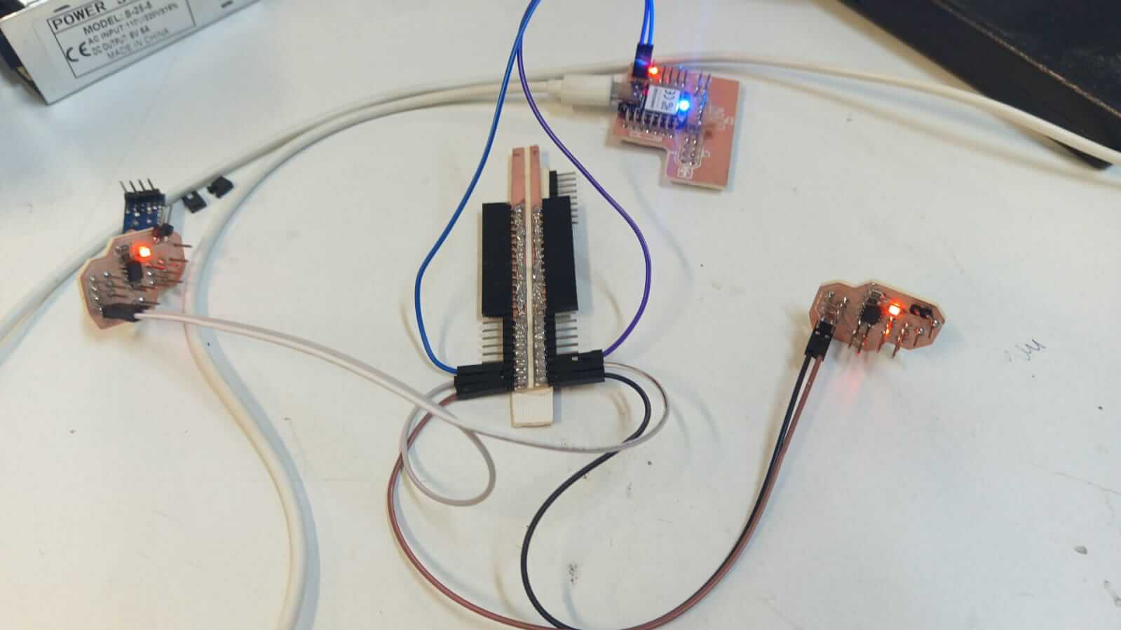
For this week, I planned a communication setup between a XIAO RP2040 and a pair of ATtiny412s using I²C. The only goal I had in mind was something simple: I just wanted to be able to request one of the secondary nodes to turn on an LED on one of its pins.
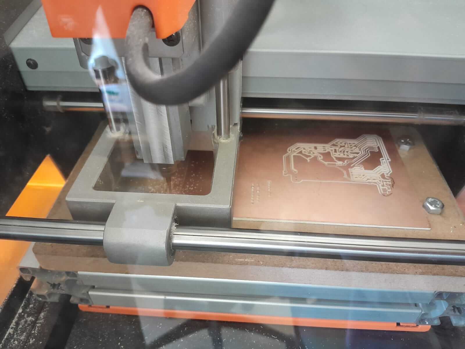
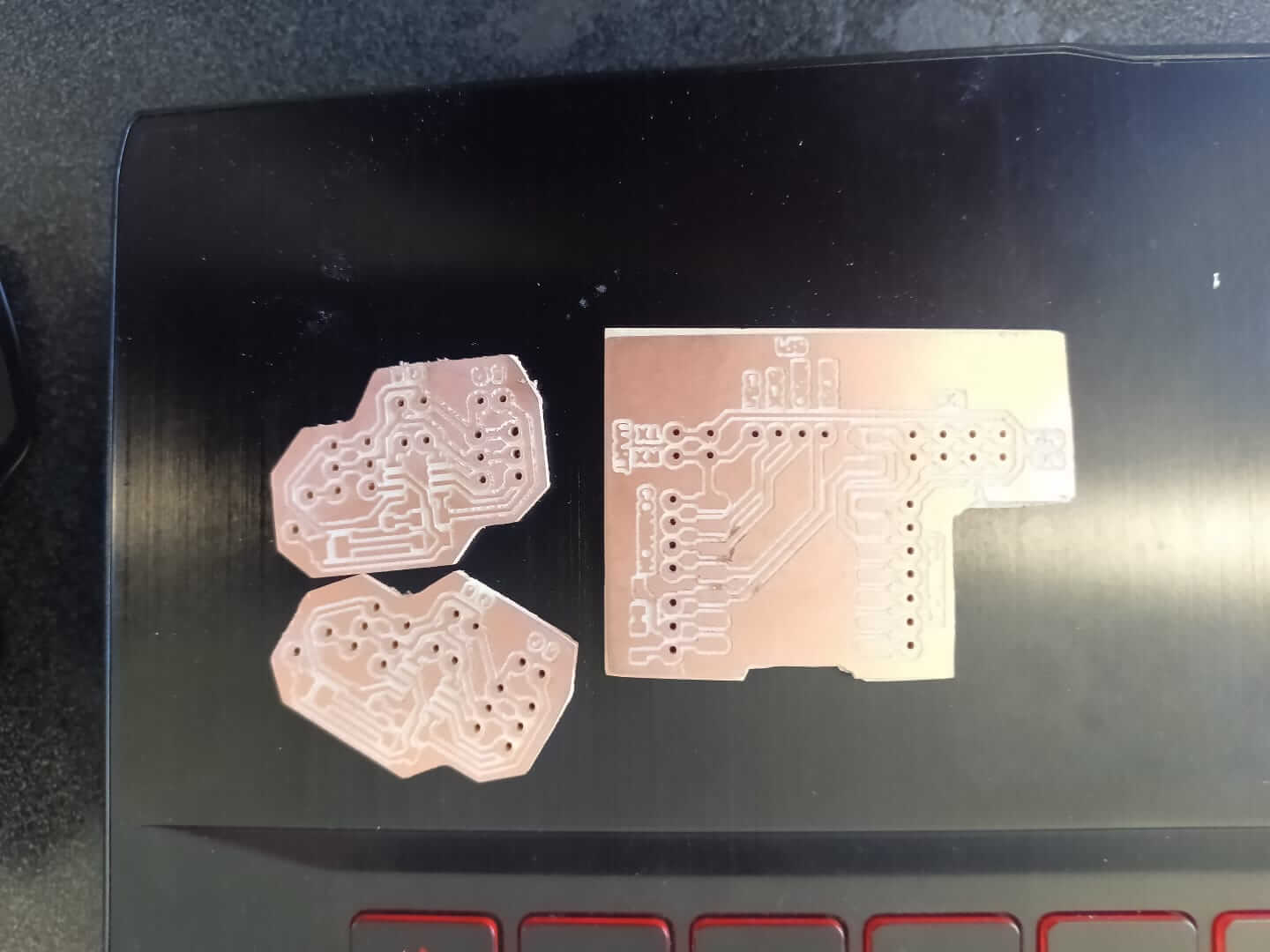
Here are a few images of the new boards I made for this week. Basically, one is for my XIAO RP2040 where I added header pins, and the other two are for some ATtiny412s, so everything can be controlled via I²C.
Here's the code I used for a xiaorp2040 as master:
#include// Include the I2C library void setup() { Wire.begin(); // Initialize I2C as master Serial.begin(115200); // Start serial communication for input/output Serial.println("Format: "); Serial.println("Example: 0x10 0 1 → Turns ON LED on pin 0 of slave 0x10"); } void loop() { if (Serial.available()) { // Check if there's serial input String input = Serial.readStringUntil('\n'); // Read full input line input.trim(); // Remove extra spaces or newlines if (input.length() == 0) return; // Skip empty lines // Find the positions of the first and second space int s1 = input.indexOf(' '); int s2 = input.indexOf(' ', s1 + 1); if (s1 == -1 || s2 == -1) { Serial.println("Incorrect format. Use: 0x10 0 1"); return; } // Extract address, pin number, and state from input String addrStr = input.substring(0, s1); String pinStr = input.substring(s1 + 1, s2); String valStr = input.substring(s2 + 1); // Convert to numeric values uint8_t address = (uint8_t)strtol(addrStr.c_str(), NULL, 0); // Hex string to int uint8_t ledPin = pinStr.toInt(); // Convert pin to int uint8_t state = valStr.toInt(); // Convert state to int (0 or 1) // Send data via I2C Wire.beginTransmission(address); // Start I2C transmission Wire.write(ledPin); // Send the pin number Wire.write(state); // Send the state (0=OFF, 1=ON) Wire.endTransmission(); // End transmission // Print confirmation to serial monitor Serial.print("Sent to slave 0x"); Serial.print(address, HEX); Serial.print(": pin "); Serial.print(ledPin); Serial.print(" -> "); Serial.println(state ? "ON" : "OFF"); } }
In the setup() function, Wire.begin() starts I2C communication, setting the XIAO as the master. Serial.begin(115200) initializes communication with the computer via the serial monitor, which allows the user to send commands. The println() lines are used to inform the user about the format of the command they should input.
void setup() {
    Wire.begin();             // Initialize I2C as master
    Serial.begin(115200);     // Start serial communication for the serial monitor
    Serial.println("Format:   ");
    Serial.println("Example: 0x10 0 1 → Turns ON LED on pin 0 of slave 0x10");
    }
Inside the loop(), this block waits for the user to type a command in the serial monitor. It reads the entire line until a newline character is found and removes any leading or trailing whitespace. This prepares the command string for parsing.
void loop() {
    if (Serial.available()) {                         // Check if user entered any data
        String input = Serial.readStringUntil('\n');    // Read the whole input line
        input.trim();                                   // Remove whitespace and newlines
This part checks if the user input has the correct format. It looks for two spaces separating the address, pin number, and state. If the format is invalid (e.g., missing a space), an error message is printed and the input is ignored.
if (input.length() == 0) return;                // Skip if input is empty

int s1 = input.indexOf(' ');        // Find first space (separates address and pin)
int s2 = input.indexOf(' ', s1 + 1); // Find second space (separates pin and state)

if (s1 == -1 || s2 == -1) {
    Serial.println("Incorrect format. Use: 0x10 0 1");
    return;
}
The input string is divided into three parts: address, pin, and state. These parts are then converted into numerical values: the address (hexadecimal), the pin number (integer), and the state (0 for OFF, 1 for ON). These values are necessary for sending the command to the correct slave.
String addrStr = input.substring(0, s1);           // Extract address part
String pinStr  = input.substring(s1 + 1, s2);      // Extract pin number
String valStr  = input.substring(s2 + 1);          // Extract ON/OFF state

uint8_t address = (uint8_t)strtol(addrStr.c_str(), NULL, 0); // Convert hex string to number
uint8_t ledPin  = pinStr.toInt();  // Convert pin string to int
uint8_t state   = valStr.toInt();  // Convert state string to int (0 or 1)
This section sends the parsed command to the specified slave via I2C. It begins a transmission to the target address, writes the pin number and the desired state (ON or OFF), and ends the transmission. The slave will then use this data to control the correct pin.
Wire.beginTransmission(address);  // Start I2C transmission to the slave
Wire.write(ledPin);               // Send the pin number
Wire.write(state);               // Send the state (0 = OFF, 1 = ON)
Wire.endTransmission();          // Complete the transmission
After sending the I2C command, this part prints a confirmation message to the serial monitor. It shows which slave the data was sent to, which pin was controlled, and whether it was turned ON or OFF. This helps the user verify the operation was successful.
    Serial.print("Sent to slave 0x");
    Serial.print(address, HEX);
    Serial.print(": pin ");
    Serial.print(ledPin);
    Serial.print(" -> ");
    Serial.println(state ? "ON" : "OFF");
  }
}
Here's the code I used for a pair of attiny412 as nodes:
#includevoid receiveEvent(int howMany) { if (howMany < 2) return; // Expecting at least 2 bytes (pin and state) uint8_t ledPin = Wire.read(); // First byte is the pin number uint8_t state = Wire.read(); // Second byte is the state (0 or 1) pinMode(ledPin, OUTPUT); // Set pin as output digitalWrite(ledPin, state); // Set the pin to the desired state } void setup() { Wire.begin(0x10); // Initialize I2C as slave with address 0x10 (change to 0x11 for second slave) } void loop() { // Nothing to do here – all handled via I2C interrupt }
This function is automatically called when the slave receives data from the master. It expects two bytes: the pin number and the desired state. Once received, the specified pin is configured as an output, and its value is set HIGH (ON) or LOW (OFF) based on the second byte.
void receiveEvent(int howMany) {
    if (howMany < 2) return;        // Expect 2 bytes: pin and state

    uint8_t ledPin = Wire.read();   // First byte is the pin number
    uint8_t state = Wire.read();    // Second byte is the ON/OFF state

    pinMode(ledPin, OUTPUT);        // Configure pin as output
    digitalWrite(ledPin, state);    // Set pin HIGH or LOW based on state
    }
In the setup(), the ATtiny412 joins the I2C bus with a specific address (in this case 0x10). It also registers the receiveEvent() function to be automatically called when data is received, ensuring the slave responds properly to master commands.
void setup() {
    Wire.begin(0x10);               // Join I2C bus as slave with address 0x10
    Wire.onReceive(receiveEvent);  // Register function to handle received data
    }
The main loop does nothing in this program. Since I2C communication uses interrupts, the receiveEvent() function is triggered automatically whenever the master sends data. The loop remains empty because continuous monitoring isn't necessary.
void loop() {
    // Nothing needed here - I2C communication is interrupt-based
    }
This week, the most tedious part was making three new PCBs, since I didn't have any ready for wired communication. On the other hand, getting the XIAO RP2040 to communicate with the ATtiny412s was quite challenging — for some reason, I²C communication wasn't working correctly. However, it worked *somehow*, so I reached out to classmates and professors for help. It wasn't a perfect implementation, but it managed to do what it was supposed to do.
Here you have the link to our group page
Here you can find the files of each process: