Week 05 3D Scanning and printing
Getting started with the basics of 3D printing
3D Scanning
For the 3D scanning practice, I used a Creality scanner, specifically from the Ferret series, which is quite easy to use.

I decided to ask a colleague for permission to scan his face. The process was very quick and simple thanks to the scanner's technology. Basically, all he had to do was rotate while I held the scanner in front of him.

The only indicators I needed to follow within the scanner's software were a distance indicator bar showing the optimal range between the scanner and the object, keeping it within the "Good" and "Optimal" parameters. It also has a camera to help with orientation.

After scanning the parts I considered relevant, I did not trim anything from the scan since I could do that later in the 3D printer software. So, I just processed the scan.

One drawback of the scanner is detecting the top of heads. I know there are small markers available to assist with this, but I decided not to use them to see how well the scan would turn out. Honestly, it came out pretty well, with that small exception.


To print for all the printings, I will be using Prusa's software for the MK4S printer from the same brand. The printing parameters are set to the default ones for a 0.28-millimeter nozzle configured by the software itself.
>I saved the file in .stl format for printing. I directly imported it into the printer software, cut the hollow parts, and let Windows' repair algorithm close any unwanted holes for me since I didn't feel like fixing them manually with specialized software.


I won't be able to upload any of the files from this process since they all exceed 10 Mb and here's the final result:


Printing
This are the parameters I used to print all


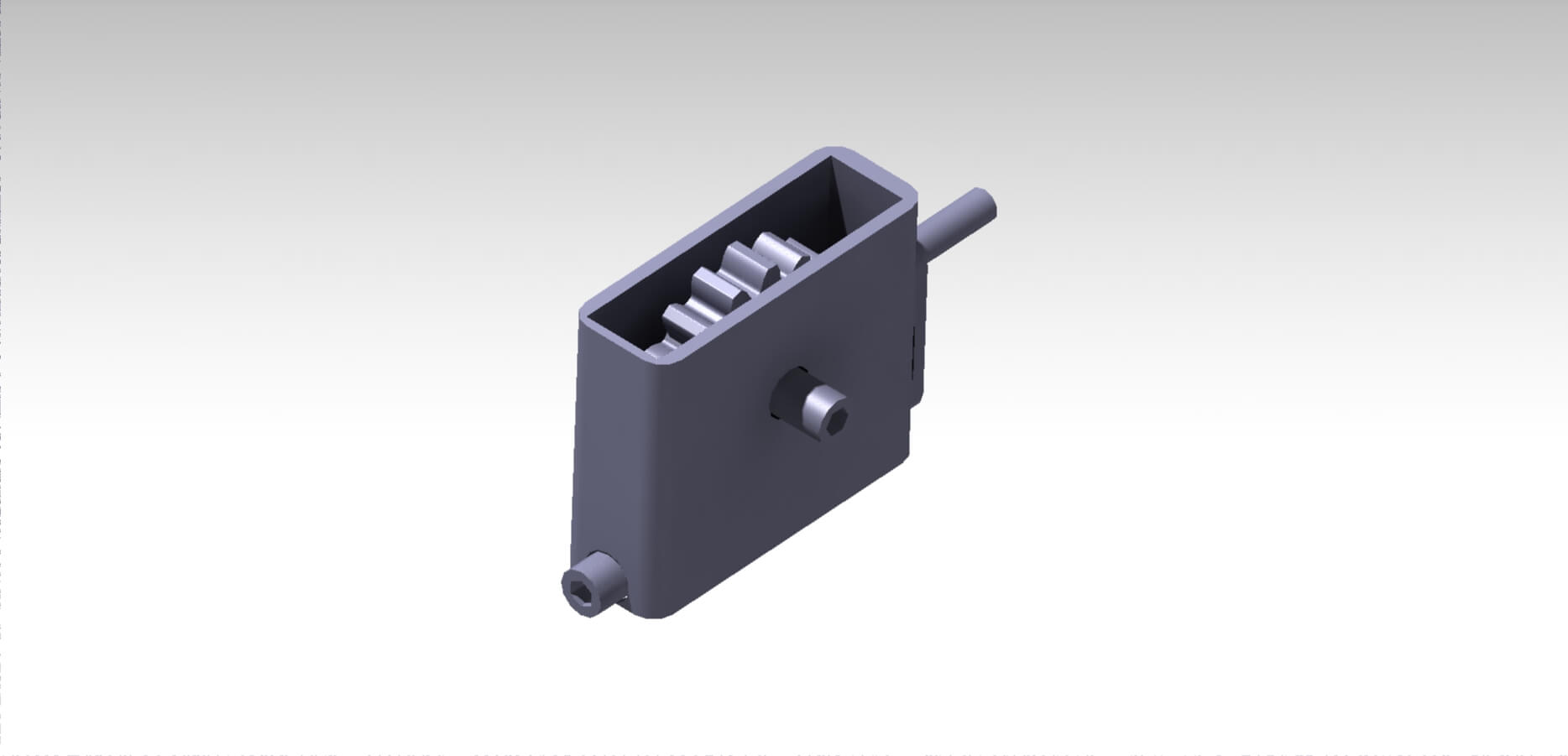
My first 3D printing idea was to create an encapsulated mechanism (which contains rotating axes with +0.3 tolerances in circles), in this case, a very simple motor gearbox. It is important to clarify that I did not perform any force transformation calculations. I just wanted to demonstrate one of the possible uses of 3D printing.

First, I created the basic mechanism, the gear, and the worm screw.

For the worm screw, I defined a helix around a cylinder. I also created a shape using two ovals, to which I applied the rib function for the worm handle.


For the gear, I created a single gear tooth and then applied a circular pattern with the appropriate number of teeth for the gear.


Next, I added a cylinder for the gear's rotation axis, while at the end of one side of the worm screw, I added a small crank. This crank includes a handle that rotates independently from the arm, as shown in the image.


Then, I added the outer casing, which holds the entire mechanism. I adjusted the dimensions so that part of the worm screw protrudes from the casing but does not fall out.


Finally, I made two holes in the casing for the rotation axes of the mechanisms.


Here you can see how it printed. In this case, I preferred tree supports to prevent the supports from being too invasive with the gears. On the other hand, if the part were printed lying down, it would be difficult for the supports to reach certain points, considering that the configuration is set to generate supports only from the base. Otherwise, it would be too difficult to remove them, especially considering that the part is designed so that tools cannot be inserted.


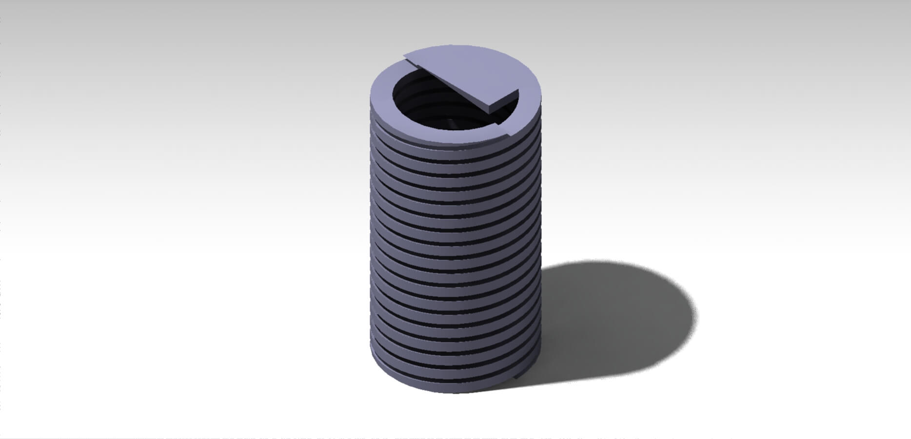
The second figure I made was two springs, one inside the other. First, I defined a pair of helices with the same dimensions for both.


I created the shape that would travel along the entire helix line.

I cut the ends so that the figure would be flat at its bases.

Finally, I added small bases so that at least one of the springs could stand upright.

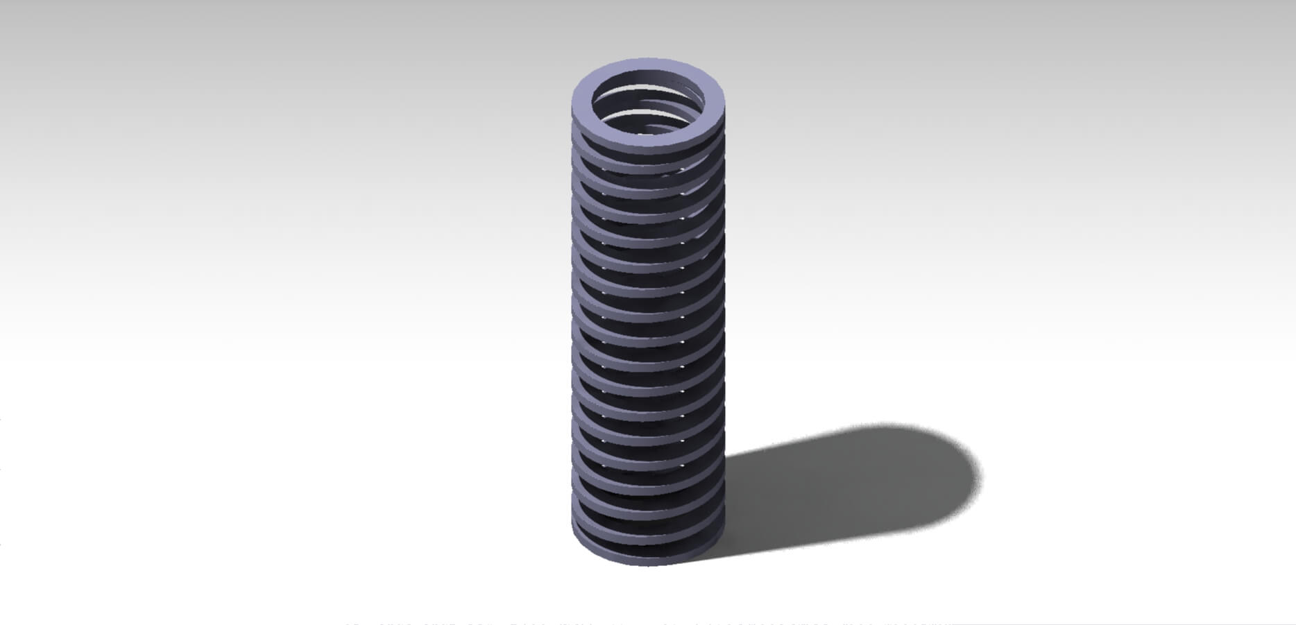
The third and final figure I made was a single, longer spring. First, I created the helix. I will omit the dimensions of the shape used for the rib, as they are exactly the same as in the previous springs.


For this spring, instead of cutting the ends, I created bases using the same faces of the rectangle used in the rib and completed both bases with the shaft function.

Here you can see how it printed. I used linear supports in this specific case; even though they are invasive, it is the best way to place them. If I used tree supports instead, it would take a long time and be more difficult to remove them. On the other hand, if I rotate the model 90 degrees to lay it down, the supports would also form in the center, and the part would be much easier to break.

Results
3D scanning


3D printing


Videos
Fortunately, during this week, I did not encounter a single problem, neither with 3D scanning nor with printing. The only thing I must say is that, since this was my first time printing springs, I was surprised by how flexible a PLA piece can be. Starting this week, I became aware of the existence of tolerances in manufacturing, specifically in 3D printing. In this case, when dealing with circumferences or connections, it is important to consider that plastic expands. Additionally, printing angles play a crucial role, requiring a solid understanding of part design, printing software, and the materials used for printing. Regarding the parts I designed, creating encapsulated gears would be a very complex or even impossible process for obvious reasons. On the other hand, while springs are not typically manufactured in this form—since metals are bent into a cylindrical shape—I found it interesting to attempt making a functional and durable spring using the most basic 3D printing filament.The designs I created are definitely very difficult to manufacture using common processes. In the case of the springs, while they could be made like a screw thread and then have the center removed, it would be challenging because the material would break easily. On the other hand, my encapsulated mechanism is unlikely to be made using lathes or similar methods, as the gears are already positioned as they should be to function. To make things even more complicated, they are inside a box, which prevents tools from accessing them directly to machine the gears from the front. Similarly, machining them from the sides is not possible either, as only one side of the gear would be made, leaving the other unfinished.
Here you have the link to our group page
Here you can find the files of each process:
