Week 04 Embedded Programming
Knowing some programming languages and microcontrollers
For this week, I used the ESP32 38-Pin ESP WROOM 32 microcontroller and retrieved its datasheet from this website:
From there, I extracted some crucial data, which are:
General Features of the ESP32-WROOM-32
- Architecture: Xtensa® Dual-Core 32-bit LX6
- Clock Frequency: Up to 240 MHz
- RAM Memory: 520 KB SRAM
- Flash Storage: 4 MB (although there are versions with 8 MB or more)
- Operating Voltage: 3.3V (Does not tolerate 5V on its I/O pins).
Communication and Connectivity
- Wi-Fi: 2.4 GHz, 802.11 b/g/n (supports AP, STA, and AP+STA modes).
- Bluetooth: Bluetooth 4.2 and BLE (Bluetooth Low Energy).
- Communication Protocols:
- UART: Up to 5 ports
- SPI: Up to 4 buses
- I2C: Up to 2 buses
- I2S: Digital audio interface
- CAN Bus: CAN communication support
GPIOs and Functionality
- Total GPIOs: 34 available pins
- ADC Pins (Analog-to-Digital Converter):
- 18 channels of 12 bits (ADC1 and ADC2).
- DAC Pins (Digital-to-Analog Converter):
- 2 channels of 8 bits (DAC1 and DAC2).
- PWM (Pulse Width Modulation): Supported on almost all GPIOs.
- Internal Sensors:
- Internal temperature sensor.
- Capacitive touch sensor (10 channels).
Power Consumption and Power Saving Modes
- Active Mode: ~160 mA
- Light Sleep Mode: ~0.8-2 mA
- Deep Sleep Mode: ~10-150 µA
- Hibernation Mode: ~5 µA
Security and Cryptography
- Supports encryption: AES, RSA, SHA, ECC, and RNG.
- Secure Boot support.
- Flash protection through encryption.
Temperature and Operating Conditions
- Operating Temperature: -40°C to +85°C.
- Voltage Range: 2.3V – 3.6V (recommended 3.3V).
Programming and Compatibility
- Compatible Platforms: Arduino, MicroPython, Espressif IDF, PlatformIO.
- Debugging and Programming: Supports JTAG.
- Bootloader: Flashed via UART using TX0 / RX0.
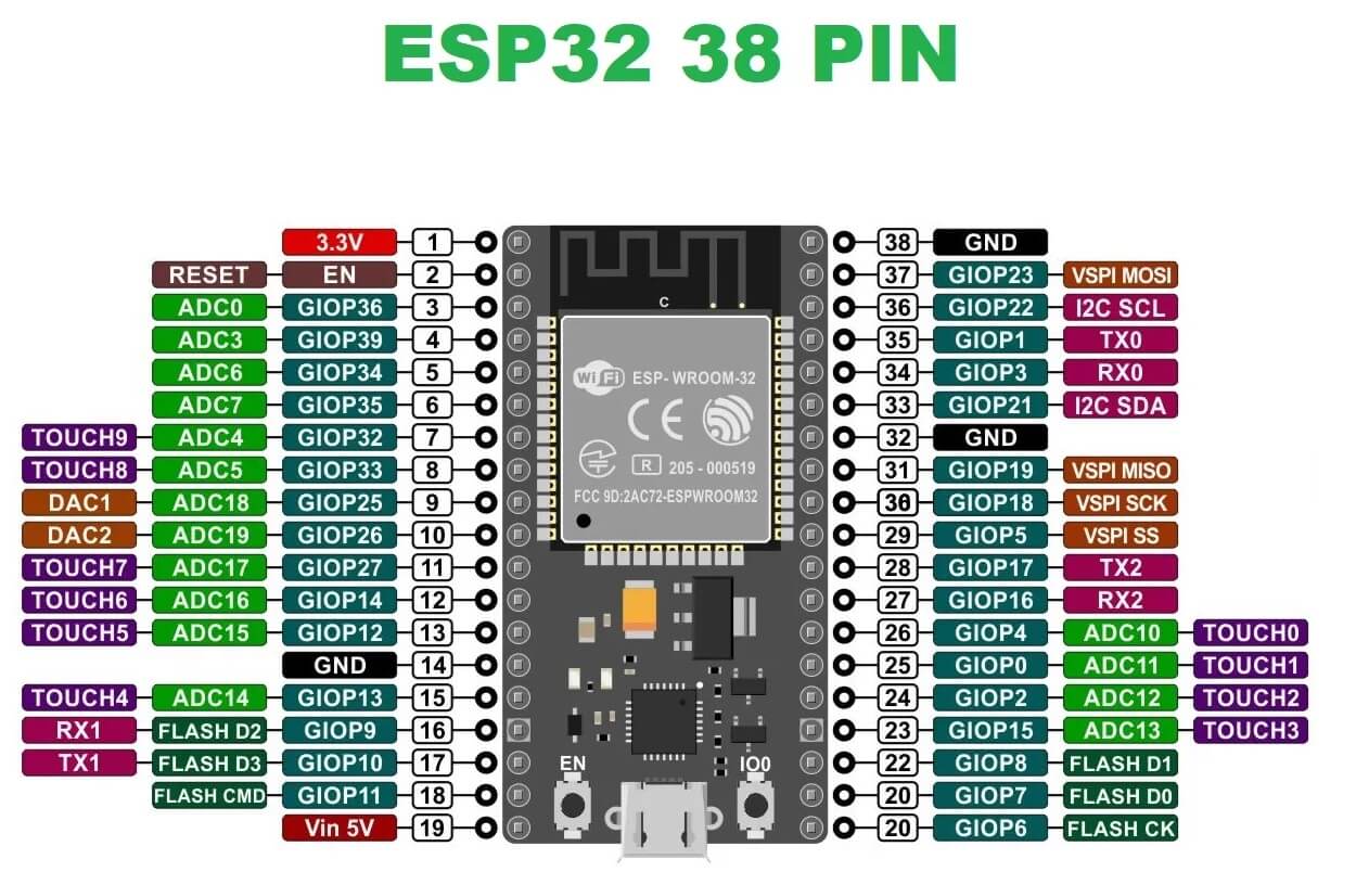
Important Pins
3.3V Power Supply: 3.3V
Ground (GND): Multiple GND available
Analog Inputs (ADC1): GPIOs 32-39 (⚠️ ADC2 is restricted if Wi-Fi is active)
DAC Outputs: GPIO 25 and 26
I2C: SDA: GPIO 21, SCL: GPIO 22
Default SPI: MOSI: GPIO 23, MISO: GPIO 19, SCK: GPIO 18, CS: GPIO 5
UART0 (for programming): TX0: GPIO 1, RX0: GPIO 3
BOOT (Flash Mode): GPIO 0 (Must be LOW to flash)
Likewise, I am using an image to identify each pin’s functions from this website, as it was the clearest one and one of the few that matched my model:
Moving on to the programming, the objective of my code is to control 2 servomotors and both the rotation direction and power of a motor using a joystick, so that it works like the rudder of a submarine. Here's an image of how my code looks like in Wokwi:
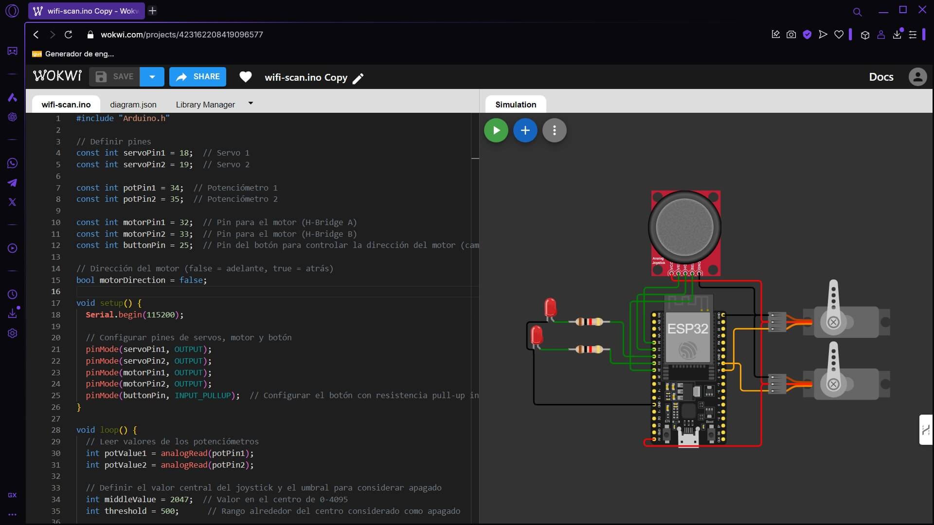
The first part of the code is simple to understand. It includes a single basic library and a set of variable declarations, nothing complex.
#include "Arduino.h"

// Definir pines
const int servoPin1 = 18;  // Servo 1
const int servoPin2 = 19;  // Servo 2

const int potPin1 = 34;  // Potenciómetro 1
const int potPin2 = 35;  // Potenciómetro 2

const int motorPin1 = 32;  // Pin para el motor (H-Bridge A)
const int motorPin2 = 33;  // Pin para el motor (H-Bridge B)
const int buttonPin = 25;  // Pin del botón para controlar la dirección del motor

// Dirección del motor (false = adelante, true = atrás)
bool motorDirection = false;
Inside the setup, I configured the servo and motor pins as outputs, as well as the button configuration as an input with an internal pull-up resistor to avoid floating signals. Lastly, but not least, I initialized serial communication at 115200 baud for debugging.
void setup() {
    Serial.begin(115200);

    // Configurar pines de servos, motor y botón
    pinMode(servoPin1, OUTPUT);
    pinMode(servoPin2, OUTPUT);
    pinMode(motorPin1, OUTPUT);
    pinMode(motorPin2, OUTPUT);
    pinMode(buttonPin, INPUT_PULLUP);  // Configurar el botón con resistencia pull-up interna
}
Inside the loop, there is the joystick reading on the X and Y axes, which vary from 0 to 4095, setting 2047 as the midpoint value for the joystick. Likewise, a threshold = 500 is defined, which helps to determine if the potentiometer is near the center and prevent it from moving the servo. The potentiometer values are converted to a range of 0 to 180 degrees using the "map()" function.
void loop(){
    // Leer valores de los potenciómetros
    int potValue1 = analogRead(potPin1);
    int potValue2 = analogRead(potPin2);

    // Definir el valor central del joystick y el umbral para considerar apagado
    int middleValue = 2047;  // Valor en el centro de 0-4095
    int threshold = 500;      // Rango alrededor del centro considerado como apagado

    // Convertir valores de los potenciómetros a ángulos (0° a 180°)
    int angle1 = map(potValue1, 0, 4095, 0, 180);
    int angle2 = map(potValue2, 0, 4095, 0, 180);
Inside the same loop, but after the previous section, there is the servo motor control, where if the potentiometer value is outside the threshold, a pulse width (500-2400 µs) is calculated to move the servo. If the potentiometer is within the threshold, the servo does not move (pulseWidth = 0). It should be noted that I did not include any library since the ones I tried to use did not allow me to upload the code or simply did not compile.
// Definir la señal PWM para el servo 1
int pulseWidth1 = 0;
if (potValue1 < (middleValue - threshold) || potValue1 > (middleValue + threshold)) {
    // Si el potenciómetro está fuera del rango central, encender el servo
    pulseWidth1 = map(angle1, 0, 180, 500, 2400);
} else {
    // Si está en el centro, apagar el servo
    pulseWidth1 = 0;
}

// Definir la señal PWM para el servo 2
int pulseWidth2 = 0;
if (potValue2 < (middleValue - threshold) || potValue2 > (middleValue + threshold)) {
    // Si el potenciómetro está fuera del rango central, encender el servo
    pulseWidth2 = map(angle2, 0, 180, 500, 2400);
} else {
    // Si está en el centro, apagar el servo
    pulseWidth2 = 0;
}
Next is the part that sends the PWM signal to the servos using the "moveServo()" function.
// Enviar señal PWM manualmente a los servos
moveServo(servoPin1, pulseWidth1);
moveServo(servoPin2, pulseWidth2);
Then comes the motor rotation direction change using a button, where I included the function "lastButtonState", which stores the previous state of the button to detect changes. Then, "currentButtonState" reads the button, and if a state change 1->0 is detected, the "motorDirection" function's value is inverted. Lastly, I included a small delay on a professor's advice to avoid multiple readings at once from a button or unintended readings.
// Leer el estado del botón
static bool lastButtonState = HIGH;
bool currentButtonState = digitalRead(buttonPin);

// Detectar el cambio de estado del botón
if (lastButtonState == HIGH && currentButtonState == LOW) {
    motorDirection = !motorDirection;  // Cambiar dirección del motor
    delay(200);  // Debounce del botón (evitar múltiples lecturas por un solo toque)
}
lastButtonState = currentButtonState;
Then, there is an attempt to control the motor speed using the joystick's potentiometers. Here, potentiometer 1 is used to adjust the motor speed. The "map()" function converts its value (0-4095) to a range of 0-255 (PWM). According to the "motorDirection" function, the motor direction changes as follows:
false → motorPin1 = speed, motorPin2 = 0 (forward).
true → motorPin1 = 0, motorPin2 = speed (backward).
// Controlar la dirección del motor y velocidad
int motorSpeed = map(potValue1, 0, 4095, 0, 255);  // Ajustar velocidad según potenciómetro 1 (0 a 255)

if (motorDirection) {
    // Motor en dirección contraria
    analogWrite(motorPin1, 0);
    analogWrite(motorPin2, motorSpeed);
} else {
    // Motor en dirección hacia adelante
    analogWrite(motorPin1, motorSpeed);
    analogWrite(motorPin2, 0);
}
At the end, there is a part of the code that uses the "moveServo()" function to manually generate PWM. This is because, once again, I had trouble uploading and compiling my code. The "pulseWidth" function determines how long the signal stays HIGH, and "delayMicroseconds(20000 - pulseWidth)" ensures a 20 ms period between pulses (with a frequency of 50 Hz).
void moveServo(int pin, int pulseWidth) {
    digitalWrite(pin, HIGH);
    delayMicroseconds(pulseWidth);
    digitalWrite(pin, LOW);
    delayMicroseconds(20000 - pulseWidth); // Periodo de 20ms
    }
Also here's a link to my simulation and the entire code:
#include "Arduino.h"

// Definir pines
const int servoPin1 = 18;  // Servo 1
const int servoPin2 = 19;  // Servo 2

const int potPin1 = 34;  // Potenciómetro 1
const int potPin2 = 35;  // Potenciómetro 2

const int motorPin1 = 32;  // Pin para el motor (H-Bridge A)
const int motorPin2 = 33;  // Pin para el motor (H-Bridge B)
const int buttonPin = 25;  // Pin del botón para controlar la dirección del motor (cambia el pin del botón)

// Dirección del motor (false = adelante, true = atrás)
bool motorDirection = false;

void setup() {
    Serial.begin(115200);

    // Configurar pines de servos, motor y botón
    pinMode(servoPin1, OUTPUT);
    pinMode(servoPin2, OUTPUT);
    pinMode(motorPin1, OUTPUT);
    pinMode(motorPin2, OUTPUT);
    pinMode(buttonPin, INPUT_PULLUP);  // Configurar el botón con resistencia pull-up interna
}

void loop() {
    // Leer valores de los potenciómetros
    int potValue1 = analogRead(potPin1);
    int potValue2 = analogRead(potPin2);

    // Definir el valor central del joystick y el umbral para considerar apagado
    int middleValue = 2047;  // Valor en el centro de 0-4095
    int threshold = 500;      // Rango alrededor del centro considerado como apagado

    // Convertir valores de los potenciómetros a ángulos (0° a 180°)
    int angle1 = map(potValue1, 0, 4095, 0, 180);
    int angle2 = map(potValue2, 0, 4095, 0, 180);

    // Definir la señal PWM para el servo 1
    int pulseWidth1 = 0;
    if (potValue1 < (middleValue - threshold) || potValue1 > (middleValue + threshold)) {
    // Si el potenciómetro está fuera del rango central, encender el servo
    pulseWidth1 = map(angle1, 0, 180, 500, 2400);
    } else {
    // Si está en el centro, apagar el servo
    pulseWidth1 = 0;
    }

    // Definir la señal PWM para el servo 2
    int pulseWidth2 = 0;
    if (potValue2 < (middleValue - threshold) || potValue2 > (middleValue + threshold)) {
    // Si el potenciómetro está fuera del rango central, encender el servo
    pulseWidth2 = map(angle2, 0, 180, 500, 2400);
    } else {
    // Si está en el centro, apagar el servo
    pulseWidth2 = 0;
    }

    // Enviar señal PWM manualmente a los servos
    moveServo(servoPin1, pulseWidth1);
    moveServo(servoPin2, pulseWidth2);

    // Leer el estado del botón
    static bool lastButtonState = HIGH;
    bool currentButtonState = digitalRead(buttonPin);

    // Detectar el cambio de estado del botón
    if (lastButtonState == HIGH && currentButtonState == LOW) {
    motorDirection = !motorDirection;  // Cambiar dirección del motor
    delay(200);  // Debounce del botón (evitar múltiples lecturas por un solo toque)
    }
    lastButtonState = currentButtonState;

    // Controlar la dirección del motor y velocidad
    int motorSpeed = map(potValue1, 0, 4095, 0, 255);  // Ajustar velocidad según potenciómetro 1 (0 a 255)

    if (motorDirection) {
    // Motor en dirección contraria
    analogWrite(motorPin1, 0);
    analogWrite(motorPin2, motorSpeed);
    } else {
    // Motor en dirección hacia adelante
    analogWrite(motorPin1, motorSpeed);
    analogWrite(motorPin2, 0);
    }

    delay(20);
}

// Generar señal PWM manualmente para los servos
void moveServo(int pin, int pulseWidth) {
    digitalWrite(pin, HIGH);
    delayMicroseconds(pulseWidth);
    digitalWrite(pin, LOW);
    delayMicroseconds(20000 - pulseWidth); // Periodo de 20ms
}
Mock code
Throughout the course of the work, I encountered several issues. The first was deciding which microcontroller to use. This wasn't a major problem, as I quickly chose an ESP32 since we have plenty of them in our lab. I also decided on the programming language fairly quickly, as I had previously worked with the Arduino IDE (I have also worked with Python, but I'm not as skilled in it). From there, the rest of the problems were mostly things like libraries not working, the code not compiling for reasons I didn't understand, among others. However, none of these issues were truly serious.
Here you have the link to ourgroup page