Week 07 Computer Controlled Machining
Making our own furniture
The institution provided us with boards measuring 1.20x2.40x0.15 meters (some measurements may vary), with which we had to design any large object. We were also informed that the machine's tolerances remain at 0.01 millimeters. In my case, I decided to make a small bookshelf to organize some loose items in my room.
In this project, instead of using the traditional dog-bone or t-bone strategies to handle inner corners in CNC milling, I chose to round them directly from the design phase. This decision was mostly based on practicality — adding fillets manually in the CAD model saved me time and avoided the extra steps of setting up those features in the CAM software.
While dog-bones are often used to allow right-angled pieces to fit together cleanly when using a round cutting tool, in my case, the design didn't require such precise insertions. The rounded corners were enough to ensure the parts worked as intended, and it simplified the process without compromising the function.
This approach also ensured that the machine could follow the toolpath smoothly without leaving material in the corners, which is a common issue when trying to mill sharp angles with a round bit. It's not the most technically “correct” method for tight joints, but it was efficient and effective for this particular piece.
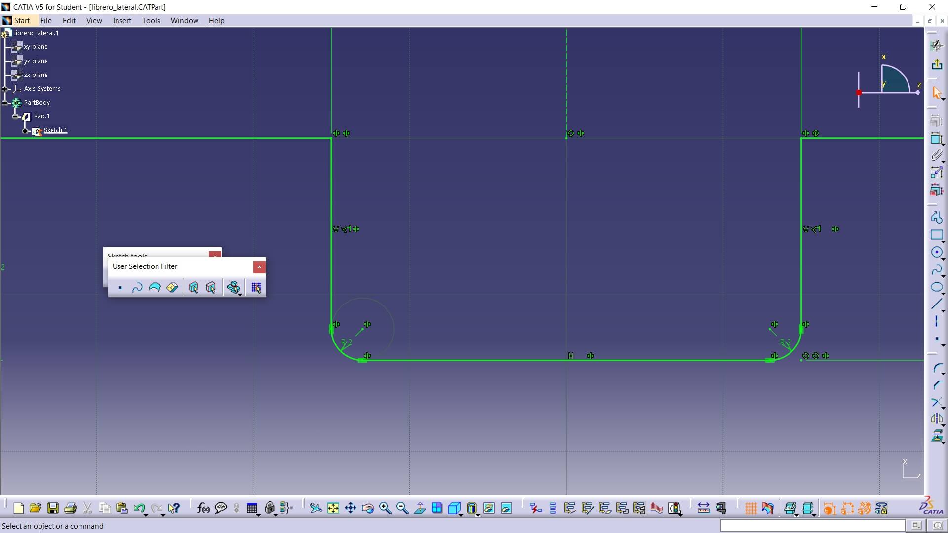
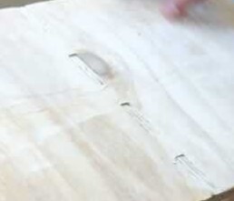
For the tolerances I used — all set at 0.2 mm — they can be seen in the image below. These are located on a tab of one of my parts. Although the machine states it has 0.1 mm tolerances, I preferred to leave a bit more clearance as a precaution, which turned out to work well.
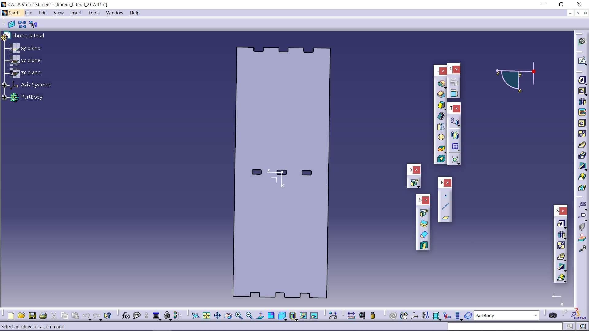
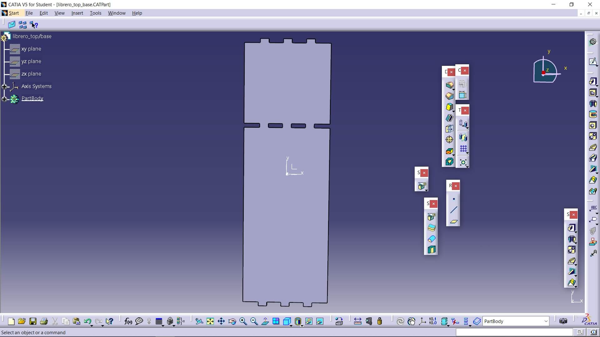
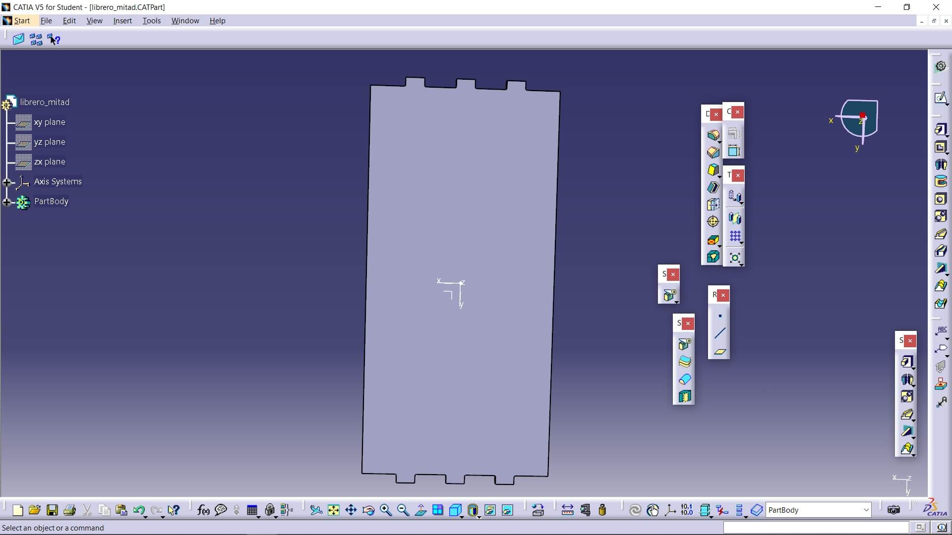
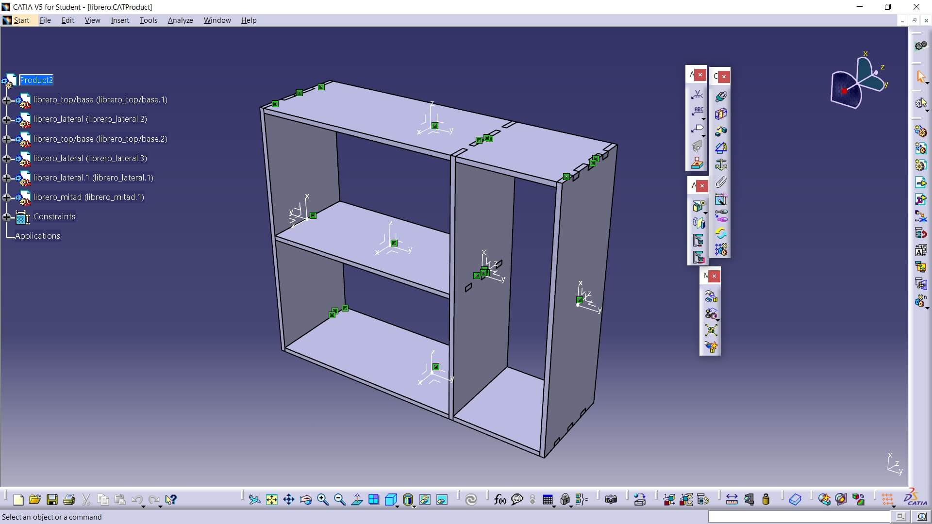
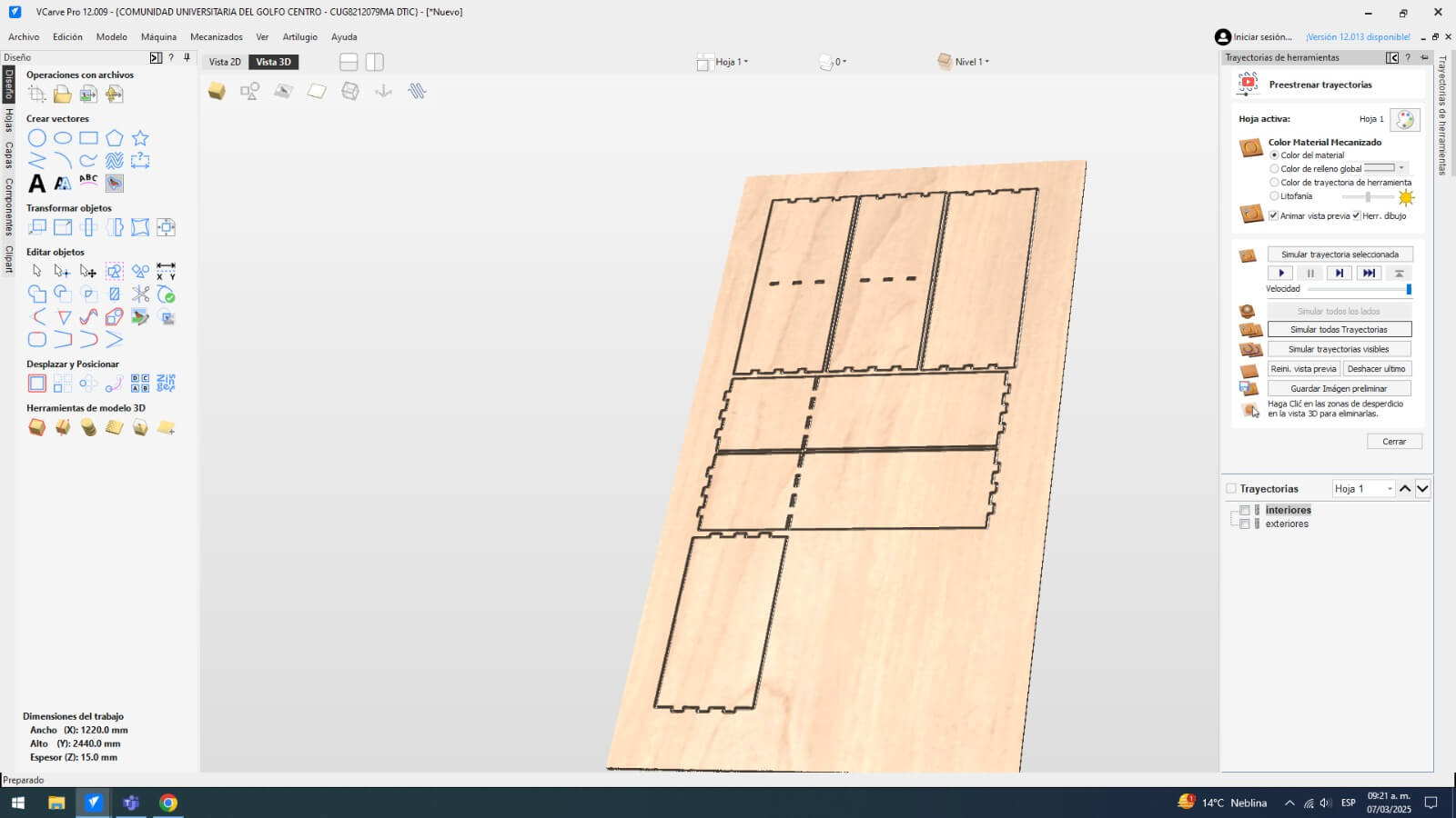
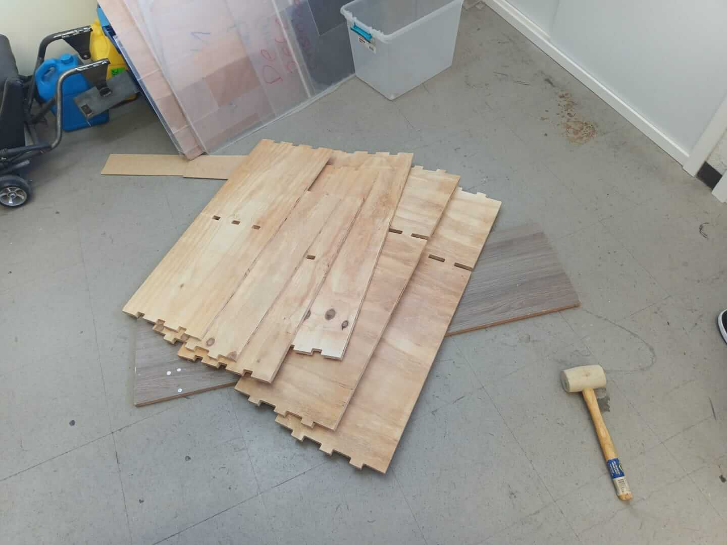
The first thing I did was design the boards for my furniture, ensuring that all of them fit within the board we were given. The design is very simple, consisting of rectangular boards with tabs to interlock them and an assembly visualization of the furniture itself.
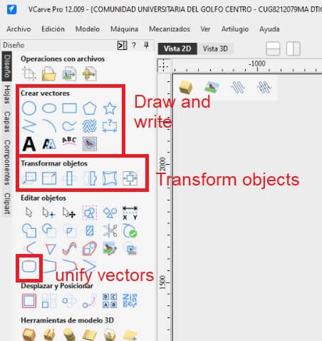
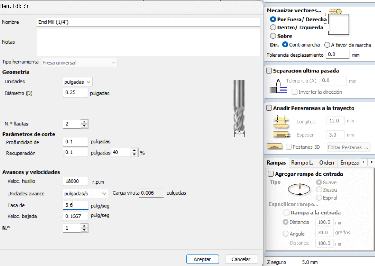
These are the tools I used within Vcarve itself.
Next, I took the DXF file of all the arranged boards and imported it into VCarve. First, I unified all the lines to convert them into a single vector and specified that everything would be cut with a ¼” diameter bit, which has two flutes, using the parameters visible in the image. Likewise, as can be seen, the cutting method was done from the outside, starting from the right.
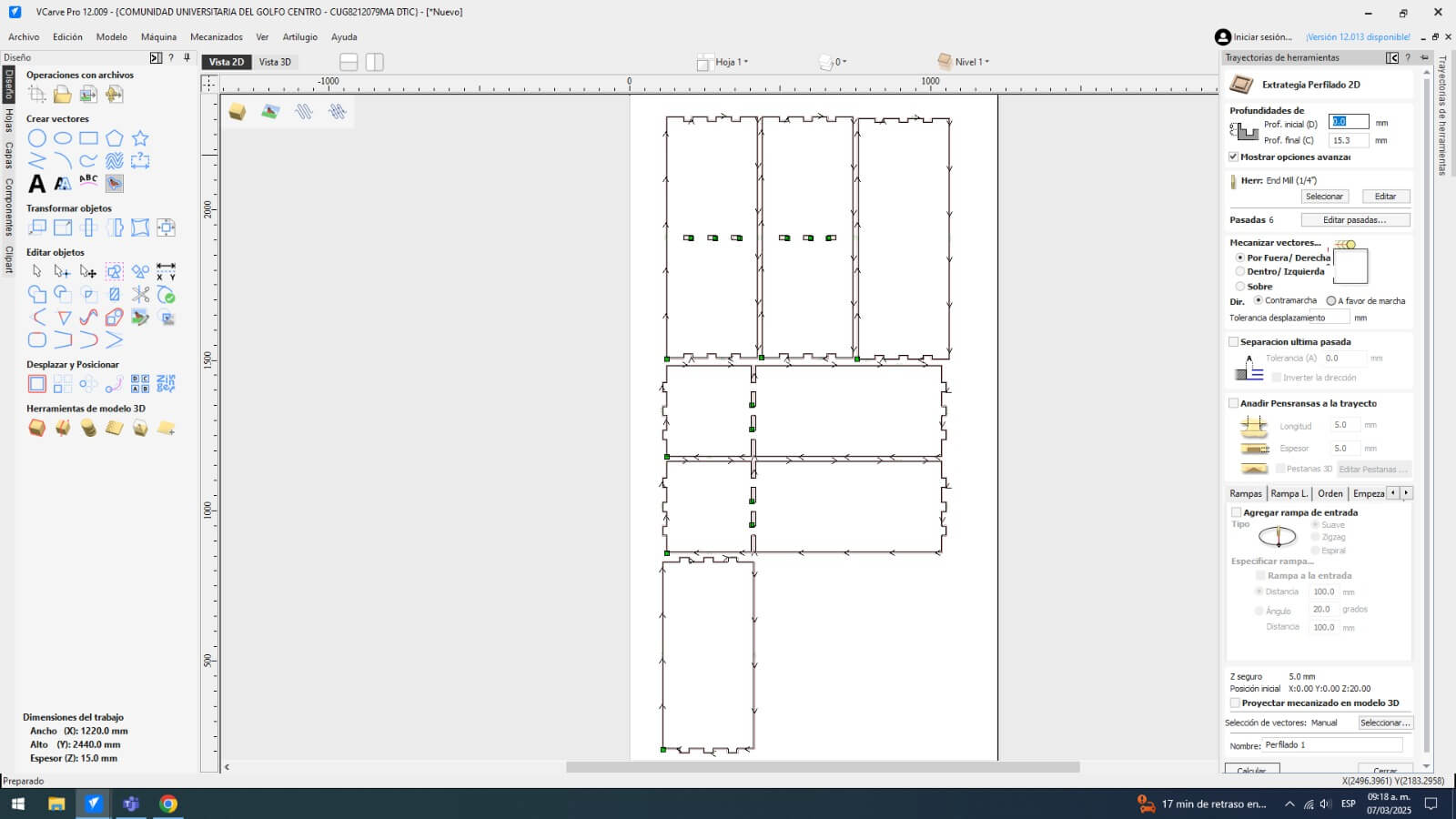
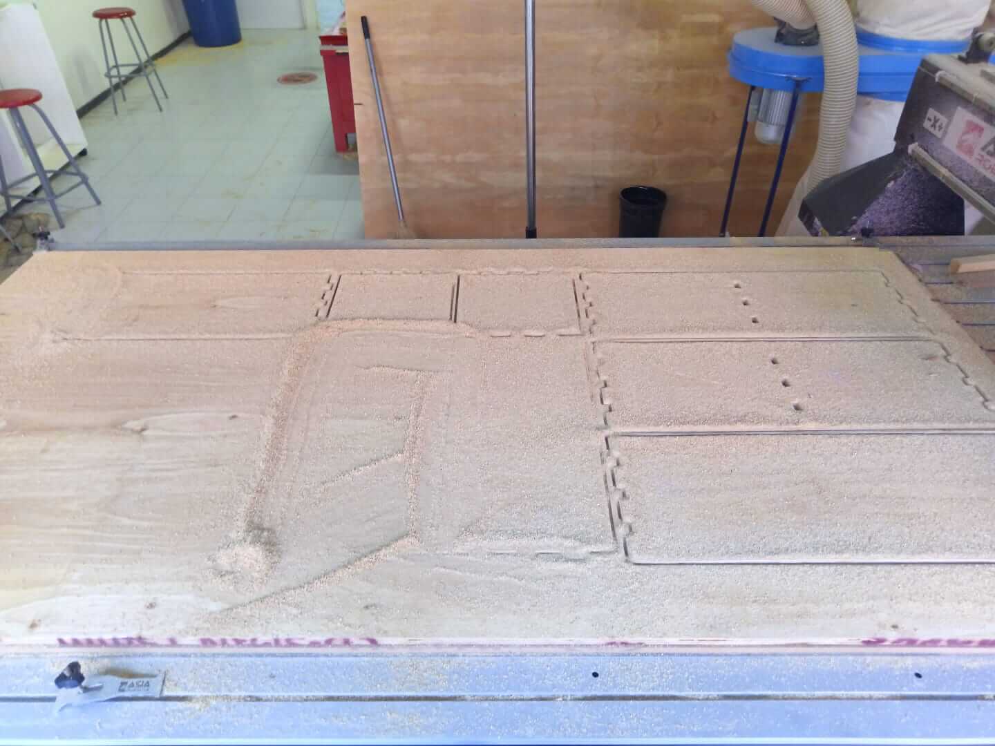
Here, you can see that the lines were correctly unified to form cutting vectors. It is important to mention that the first cuts made will be the internal holes where the boards join to prevent accidents.
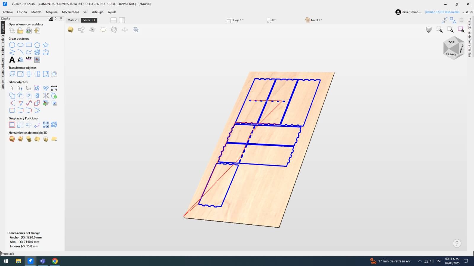
Here, you can observe how the cuts will be made according to the program.
Here you can see the cutting speeds for each tool. In our case, we are using a 1/4" Upcut Carbride End Mill.
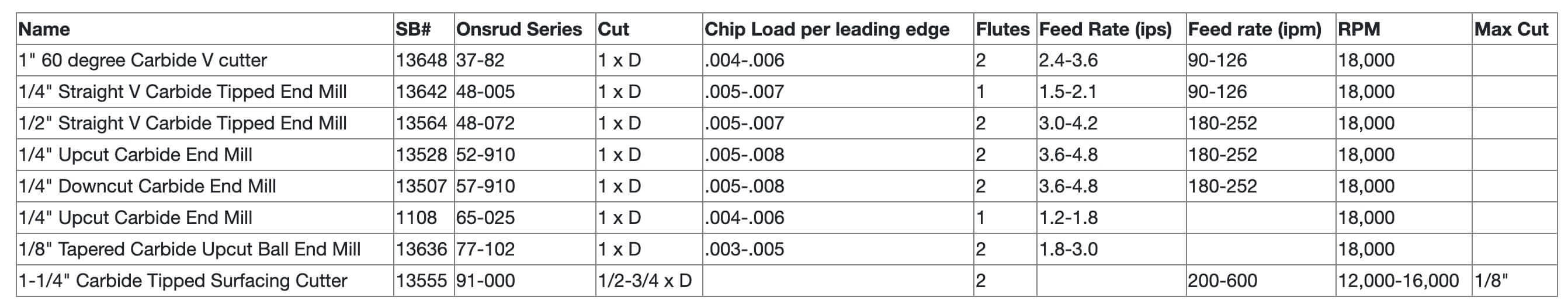
Also, here you can see the cutting speeds I used for my machining.
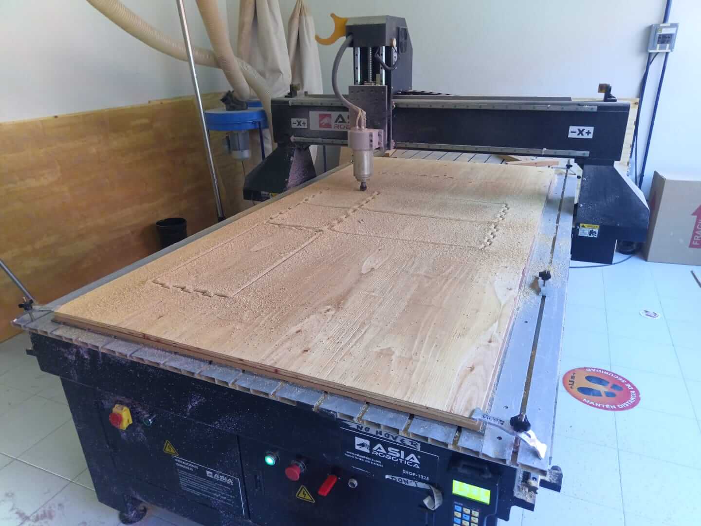
Then, at the machine, the first step (besides placing the board in position) is to set the origin for each axis.
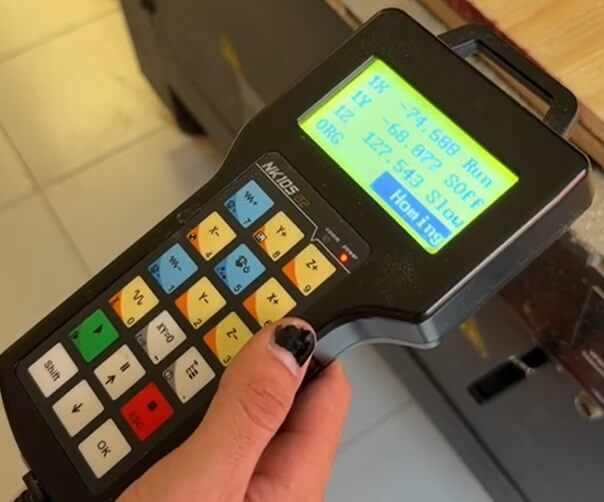
For the Z-axis origin, the professor instructed us to rotate the bit while slowly lowering it in stepping mode until the material touches the board.
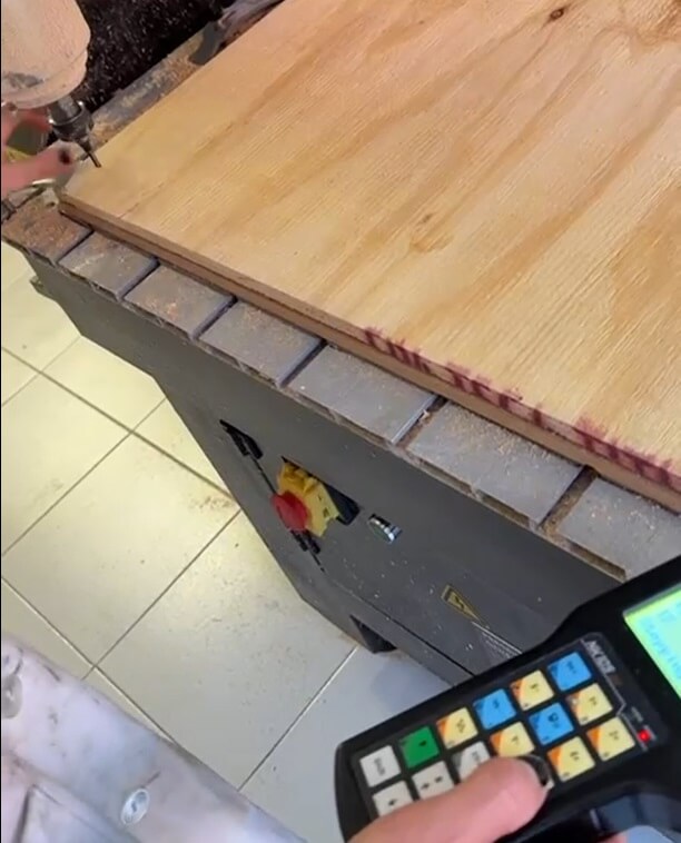
Once we set the axes to our preferred origin, we mark the zeros in the machine.
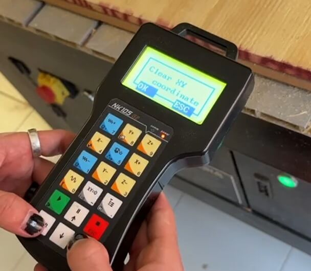
Then, we simply copy the file from a USB to the machine and load it. Finally, we just need to press the "play" button.

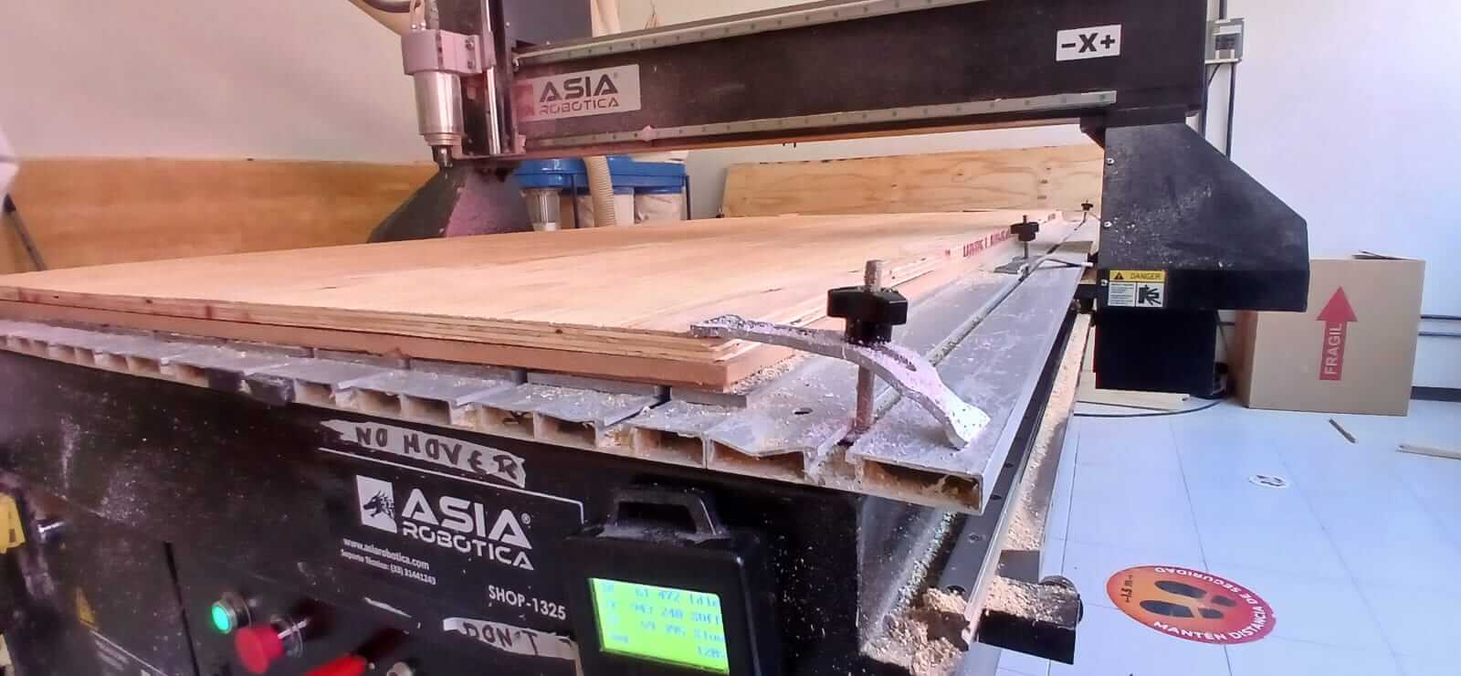
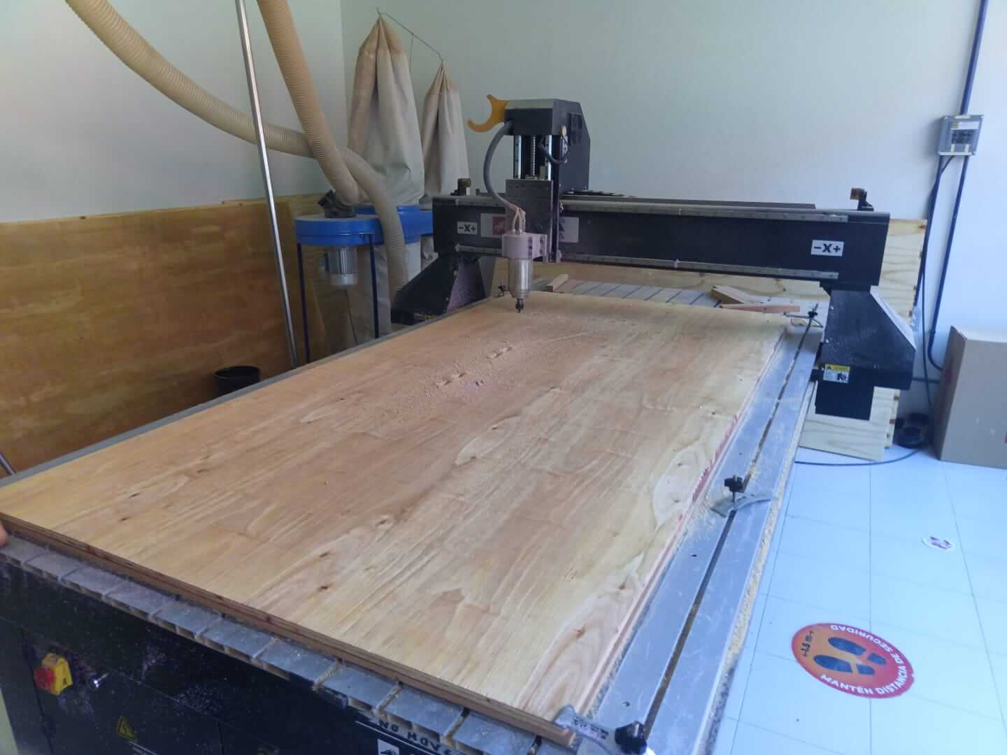
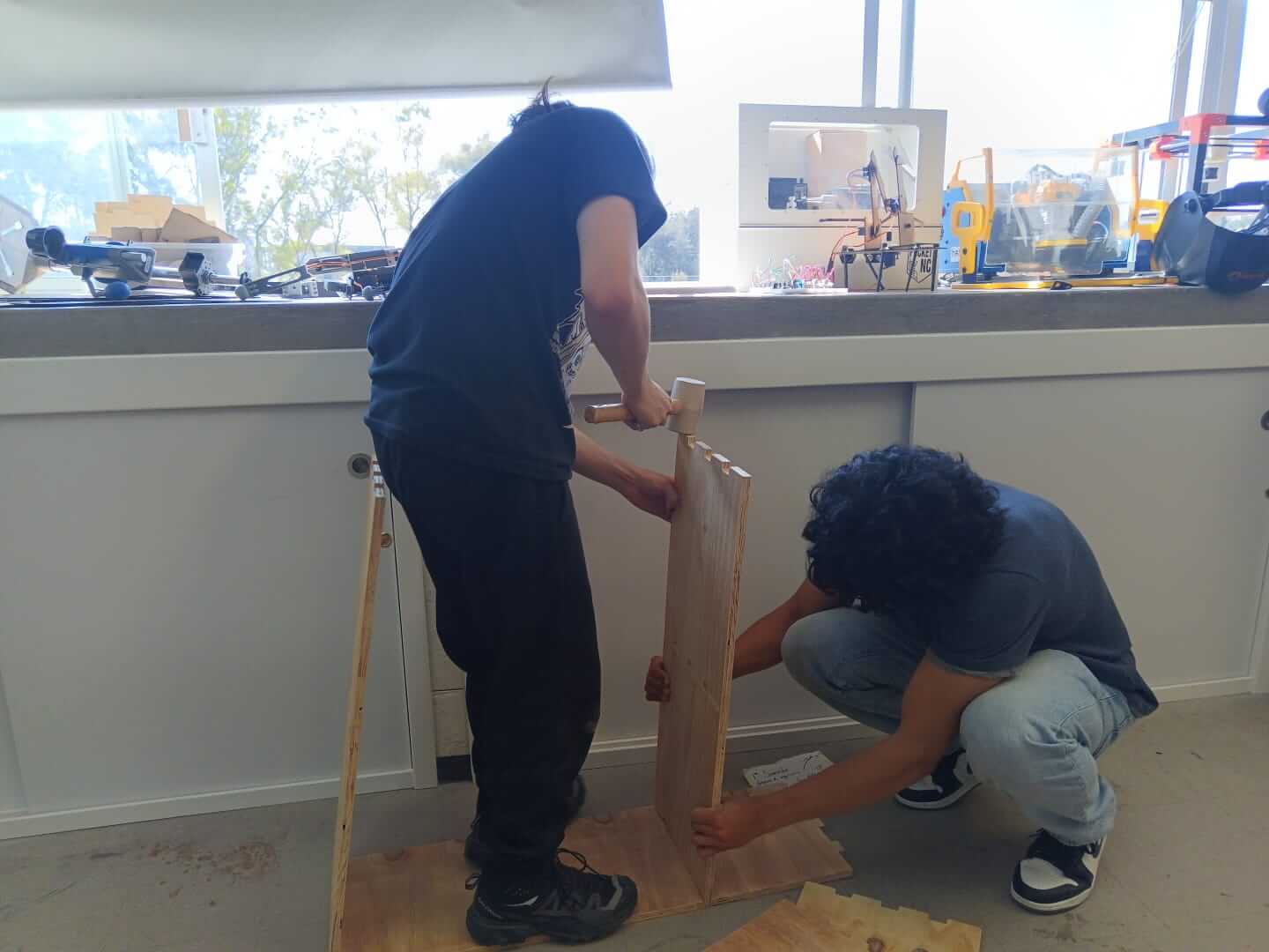
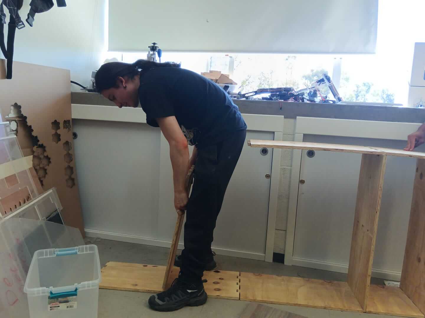
Here are some images of the process:
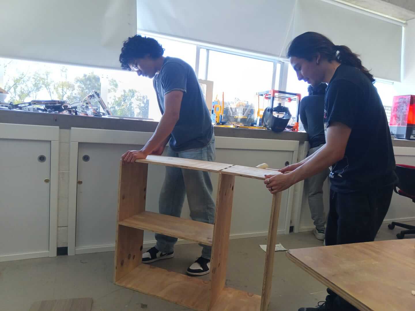
Now, here are a few images of the assembly process:
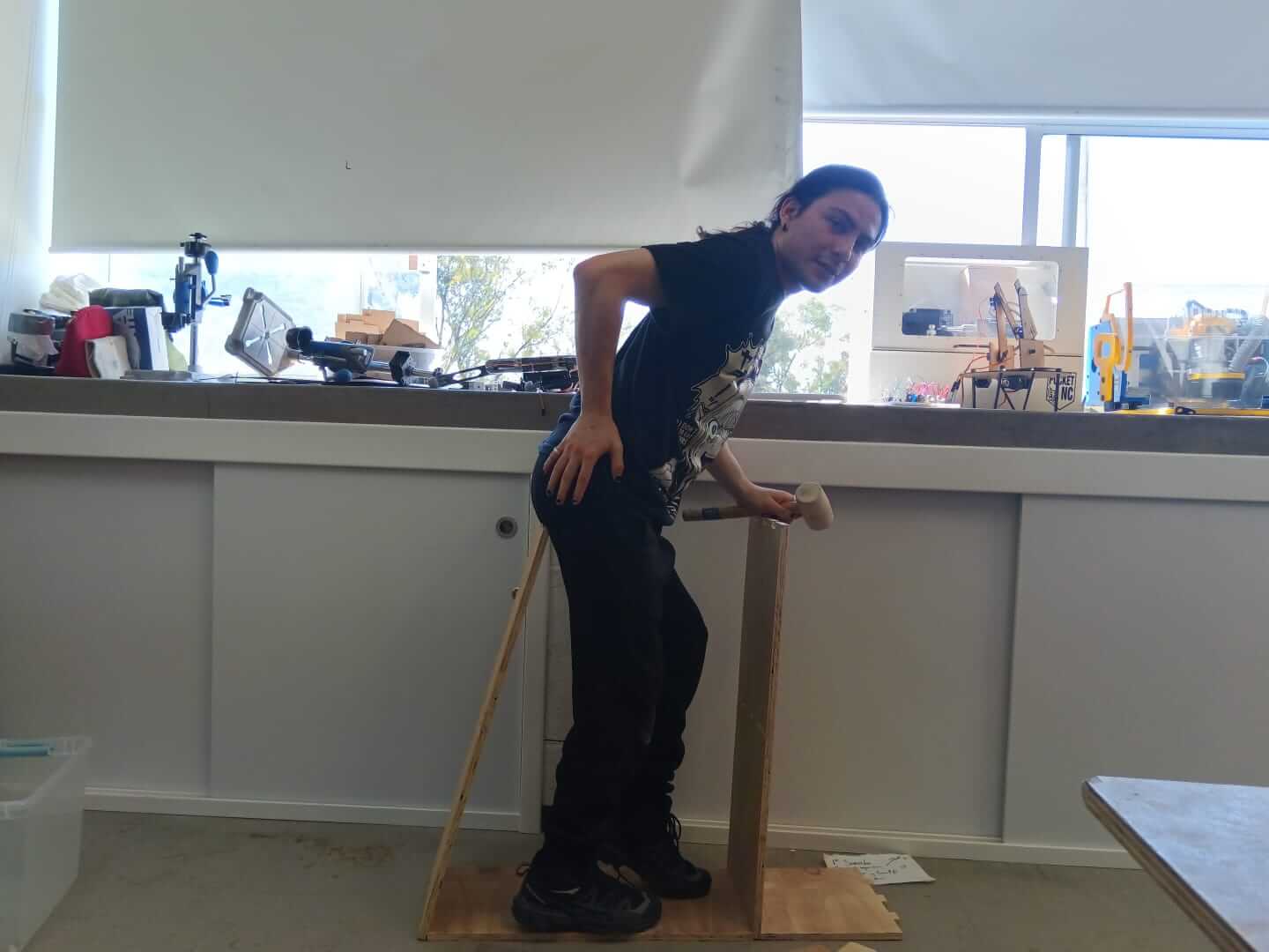
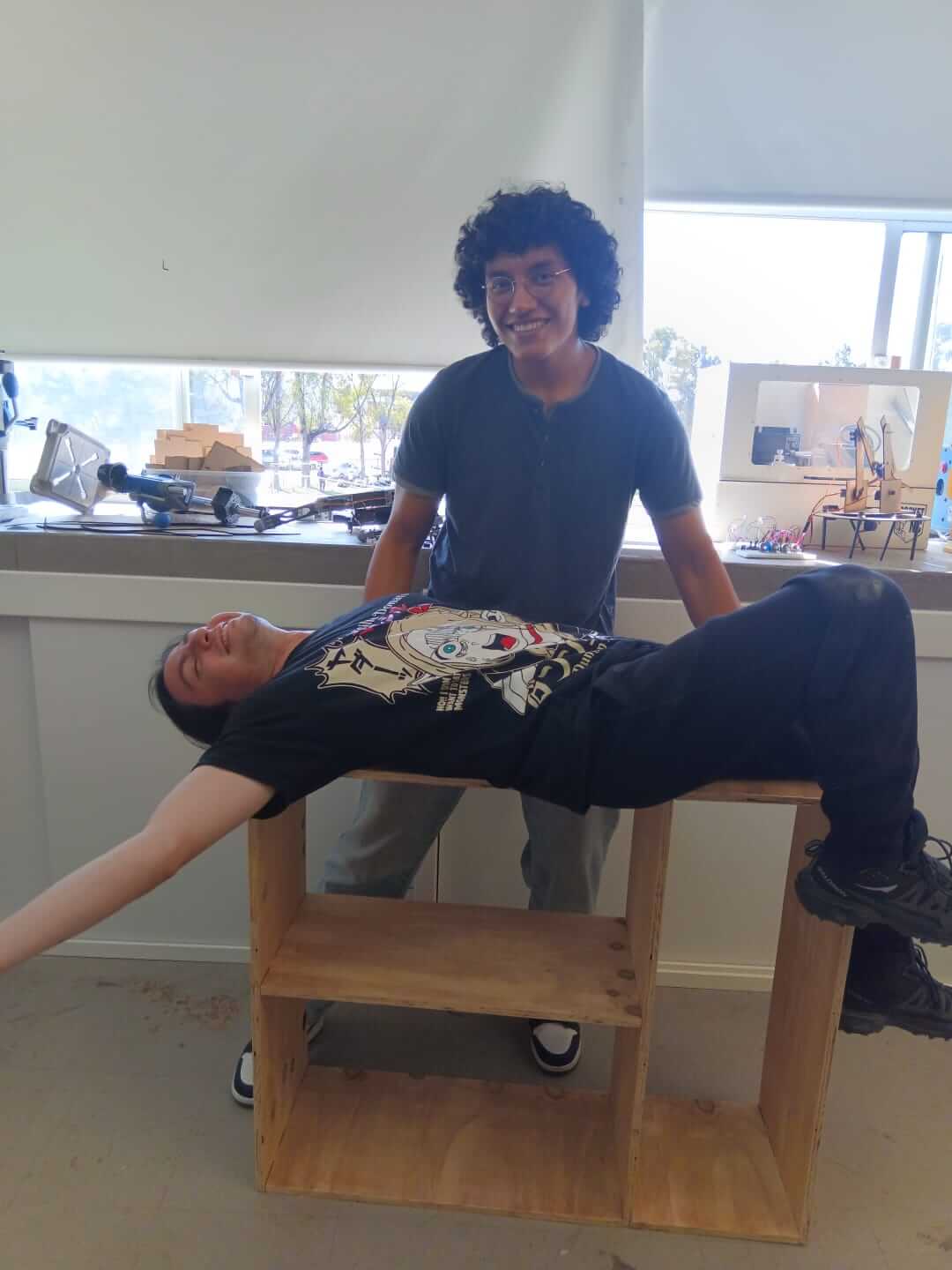
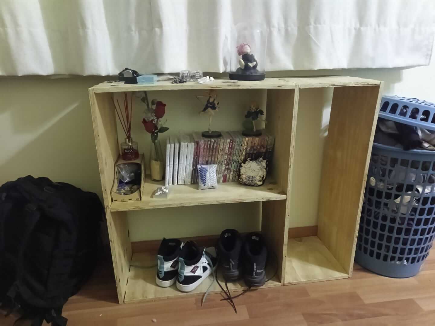
And here is the final result:
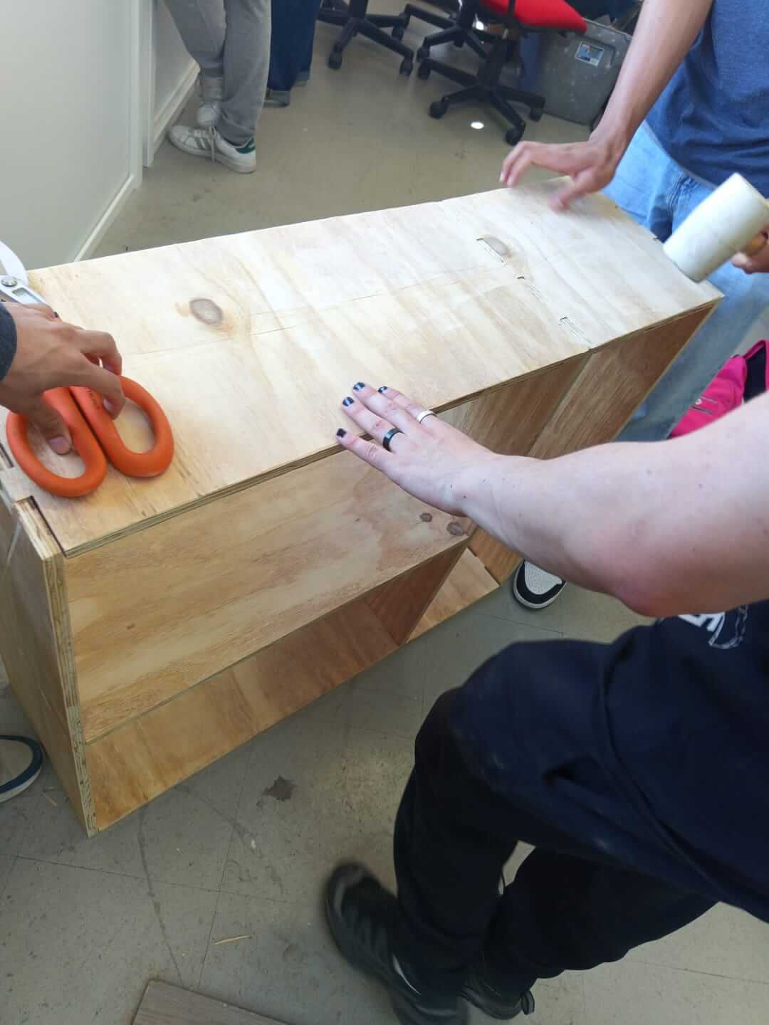
This is what the connections look like:
Videos
At the end, I had some problems because I didn't have enough neurons to realize that the furniture wouldn't fit in the car, so I arranged it as best as I could.
This week, I didn't have any problems because I had already been taught how to use this machinery beforehand. The same goes for the tolerances—since they are 0.01 millimeters, I practically didn't have to make any adjustments for my boards to fit together. Likewise, there were no issues deciding what I wanted to make since I had been wanting a small shelf for a while.
Here you have the link to our group page
Here you can find the files of each process: