9. Output Devices
Output devices are hardware artefacts that helps to comunicate, move, generate an action by
transforming digital information from a microcontroller. Such as audio (speakers), displays
(screen), motors, leds, between others.
For this week I started doing an audio speaker and use an OLED display.
Group Site
Click Here.
Speaker
In every device we use nowadays we can listen to audio or play music, this sound is produced by
a microcontroller that send the signal to an speaker.
For a better understanding of how it works we need to understand the signals we get from our microcontroller
All microcontroller are digital, this means it can control outputs by changing it Pulse Width Modulation (PWM), in my case
for the ESP32 board I made on week 8, Click Here.
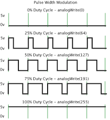
PWM
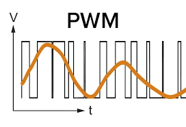
Is a digital signal that allows to vary how much time the signal is high (trying to be analog). The signal can only be high or low, the only thing we change is the proportion of time the signal is high or low. The high value depends on the microcontroller output voltage.
So with a PMW wave we can simulate analog signals.
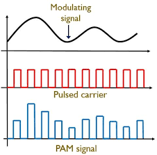
Analog Signals
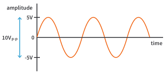
Is a time varying signal with a lot of values in constant change. So having an analog signal for audio is the best option for not loosing information. When plot a graph, it shows a smooth and continuous curve with Amplitude.
Thanks to the ESP32 and 2 DAC convertors built in we can send directly an analog singal output. A DAC or Digital-to-Analog conversion, convert the digital signals (PWM) to a continuous one. For the ESP32-wroom32 we have an 8-Bit DAC.
Circuit and it's implications
Now that we have an analog signal of output from 0 to 3.3 volts we have to send it to a speaker. Here we face the first problem, we have to amplify the voltage of the signal and the current without loosing any information.
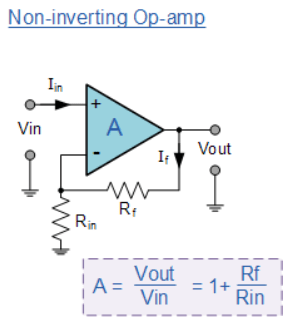
Op-amp
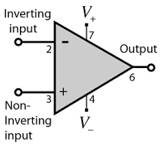
Opamp or Operational amlifier is an integrated circuit that depending on its configuration yo can compare voltage, amplify signals, do arithmetic operations or filter signals. It has to inputs and one output, also a VS (positiva and negative). This device only power up the voltaje, keeping the current zero in the input. Like we want to have a gain in our voltage signal from the ESP32 we make an amplificator configuration.
Now we face our second problem, we have to add a power component to increase the current before sending the signal to the speaker, for this we will use a transistor.
Transistor
Transistors are used to control the flow of current in devices. They operate as amplifiers or switches, depending on the configuration (conection) of it. We can compare them to a water flow for better comprehension, where the water is the current and the water key is the colector, so when a signal is detected it let the water flows.
We have to add an amplifier and a transistor into a circuit to amplify the ESP32 signal.
Simulation
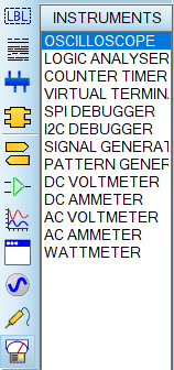
As always when we work with electronics its always usefull to test in a software if the values we choose works or to prevent any damage while conecting the circuit. There are different softwares, such as:
- Multisim
- Proteus
- Falstad
- Thinkercad
- CircuitVerse It's up to you which one you are going use. Falstad and circuitverse are online and free.
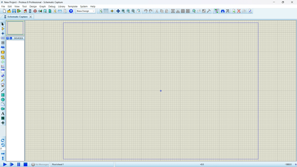
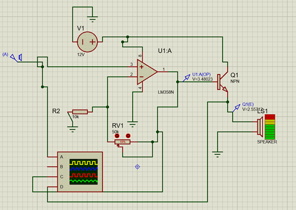
Proteus
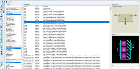
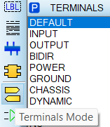
After a lot of tries of different circuits that the amplification didn't work or the transistor lower the opamp amplification or some resistor burned, etc.
I got a circuit that can amplify at different voltages thanks to a potenciometer in R2, where we change the gain of the opamp and the transistor let the current flow higher.
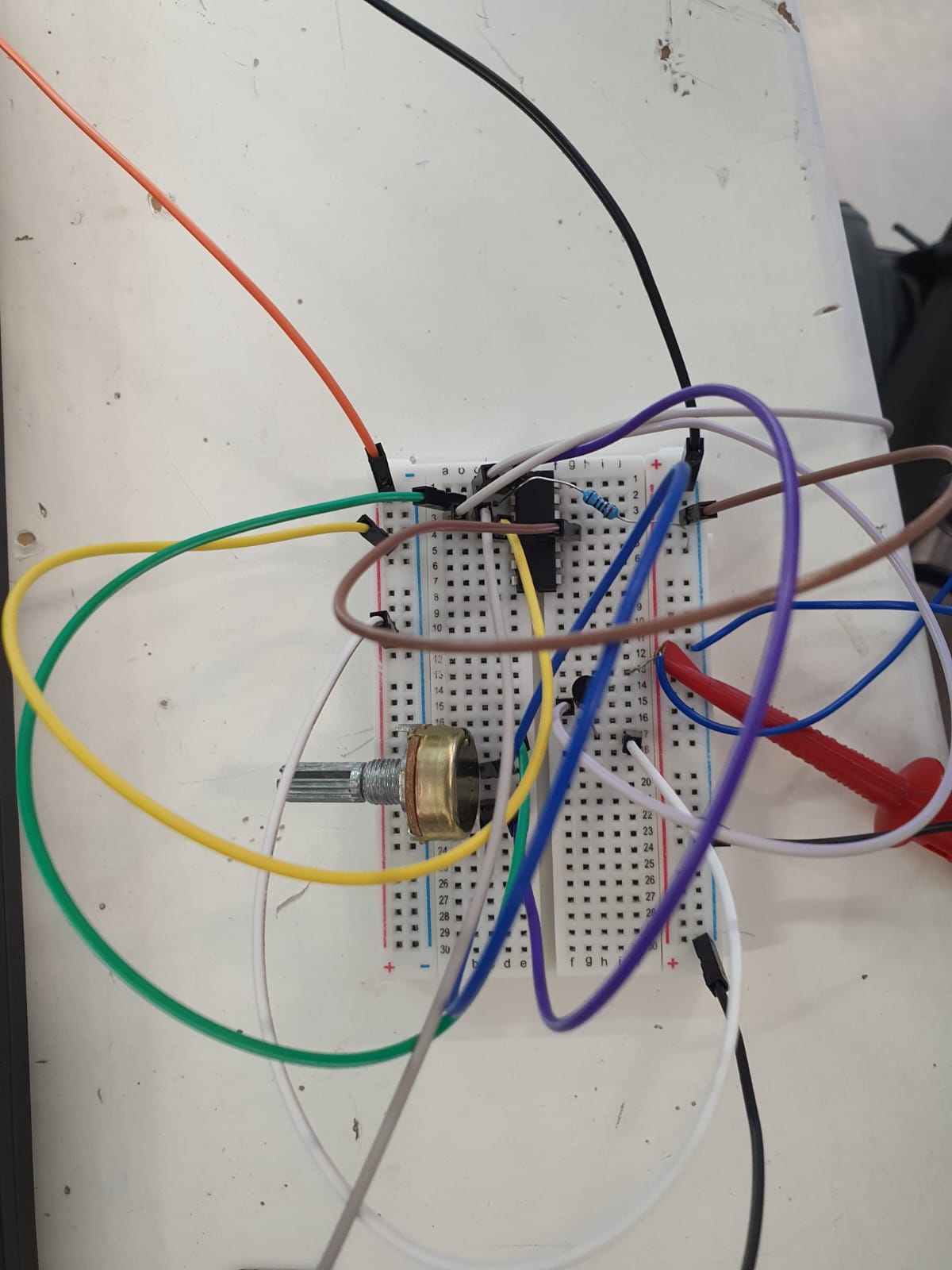
Protoboard
Once we tested in the simulator it is time to try it in physical, for the fisrt time and for test I'm going to assemble it in a protoboard with true hole components. I used the components from the simulator and a tiny speaker.
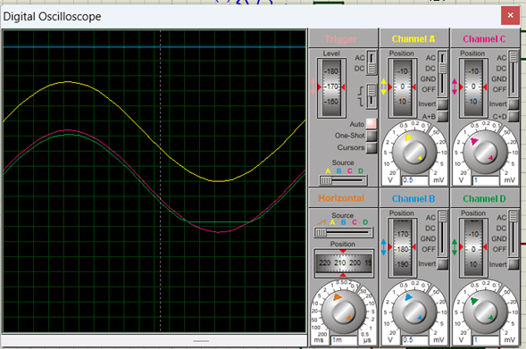
After the assembly and loading a code of a sine wave in the ESP32 I only heard a tiny pulse, no matter which gain I had. I dind't know if the circuit was working as it supposed to, so with the help of the osciloscope I meassured the input and the output.
						//Library for dac
						#include

						// Definir la tabla de valores de la onda sinusoidal
						const uint8_t sinWave[] = {128,140,153,165,177,188,199,209,218,226,
						234,240,245,250,253,255,255,255,253,250,245,240,234,226,218,209,199,
						188,177,165,153,140,128,115,102,90,78,67,56,46,37,29,21,15,10,5,2,0,0
						,0,2,5,10,15,21,29,37,46,56,67,78,90,102,115};

						void setup() {
							// Init the DAC
							dacWrite(25, 128); // Write in PIN 25 of the ESP32 and a initial value
						}

						void loop() {
							// Play the sine wave
							for (int i = 0; i < sizeof(sinWave); i++) {
							dacWrite(25, sinWave[i]); // Send the value of the wave in the output port
							delayMicroseconds(6667); // Speed at 150 Hz
							}
						}
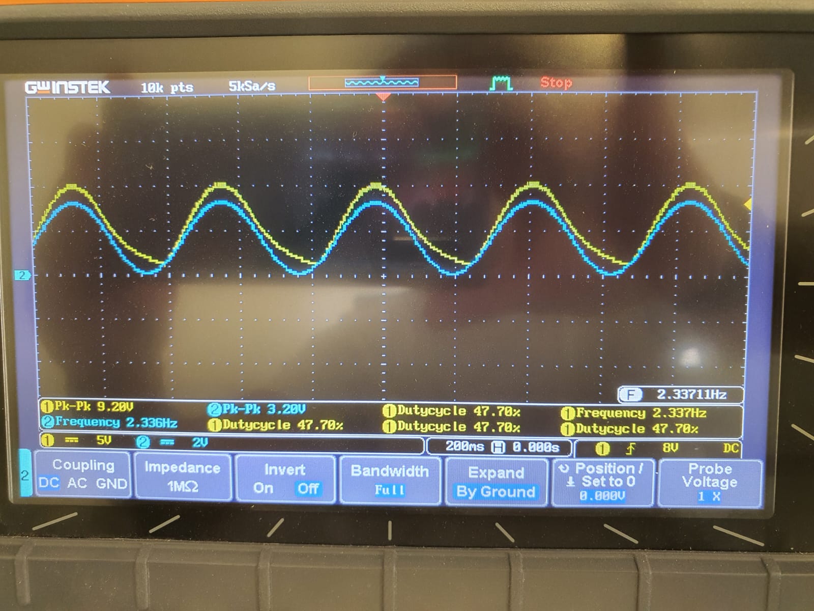
As we can se in the image above the amplification is working, I can add a filter to have a better signal, but I just didn't know why it didn't produce a louder sound, becose the signal went from 2.5v to 9.5 volts. I don't know why it didn't work, because of the speaker or something else.
OLED Display
Is a monochrome (black/white) OLED graphic display with 128 pixels wide and 32 pixels deep. It can be controlled for I2C protocol and a 3.3v.
I2C
The OLED display works with I2C comunication, but what is it??
I2C comes from Inter integrated Circuit is a protocol to comunicate with one or more chips. It consist of 2 signals: SDA (Data) and SCL (serial Clock).
Arduino
-
Steps:
- Install the Libraries
- Sketch -> Include Library -> Manage Libraries
- Install SSD1306
- Install all, this includes the GFX
-
What you can do:
- Write text
- Scroll text
- Add fonts
- Draw shapes
- Invert color
- Images
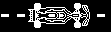
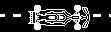
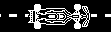
For testing it i will create an animation of different images.
Paint
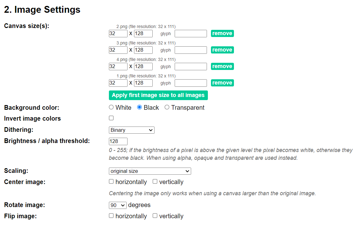
We start in Paint 3D (pixels) and configure the canvas to 128 x 32 pixels.
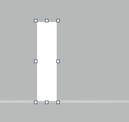
We have 2 options
- Create our own image
- Upload an image from the web
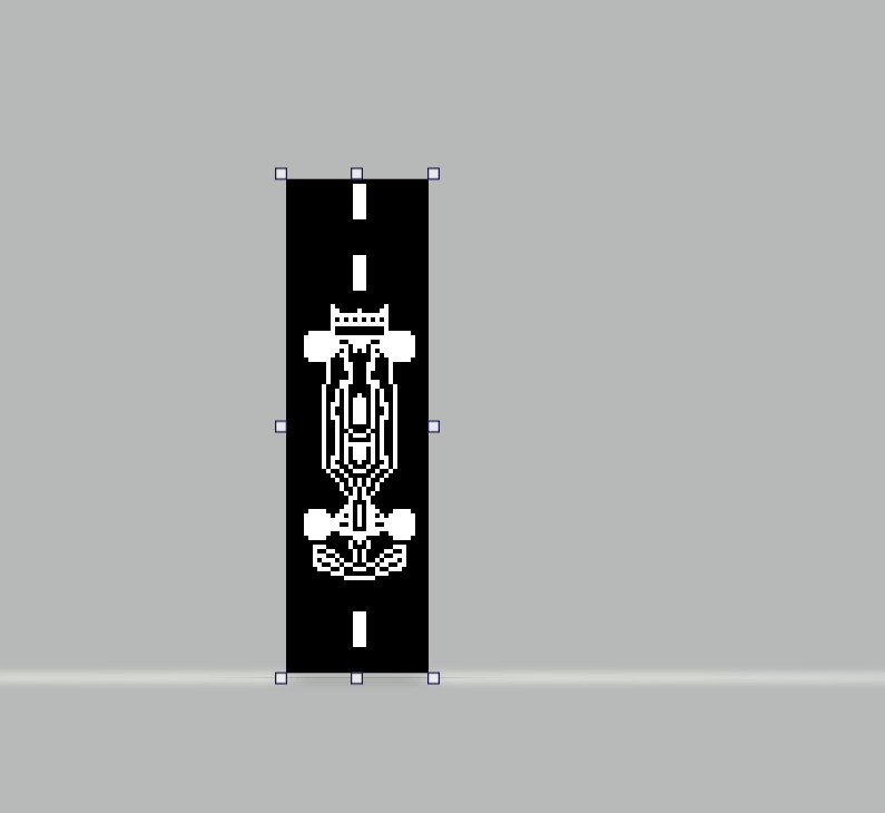
Once we save the image we go to a converter from image to byte, I used this one.
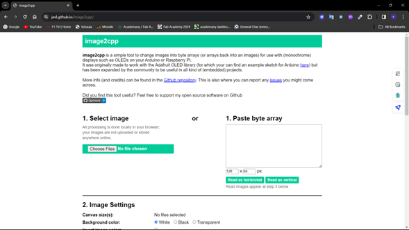
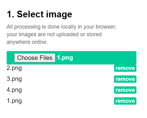
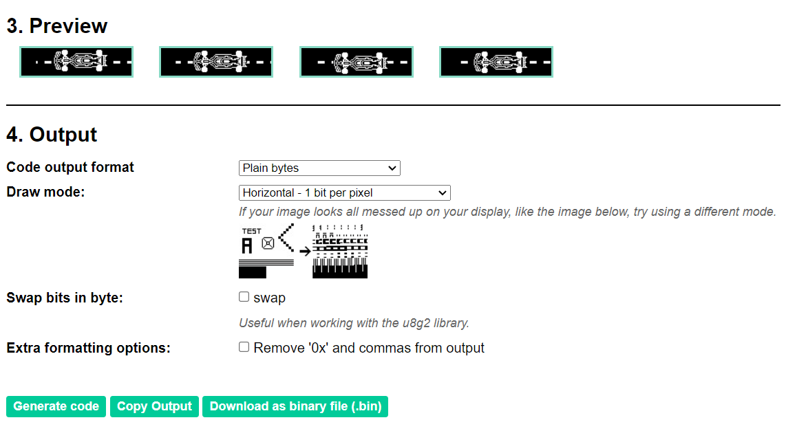
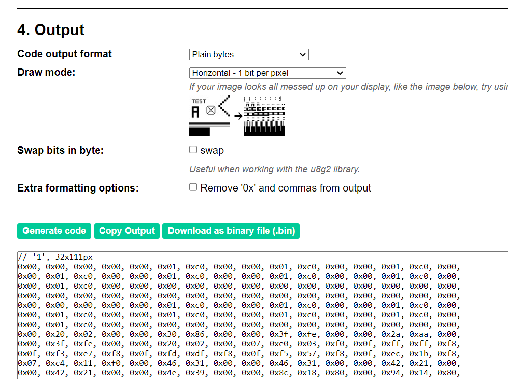
When we have the code we paste it in arduino and we only call the function, as simple as that.
My Code for the Display
First we include the Libraries for the OLED Sceen.
						#include Adafruit_GFX.h
						#include Adafruit_SSD1306.h
Constants for screen width, height, reset pin and mac adress for I2C comunication.
						#define SCREEN_WIDTH 128
						#define SCREEN_HEIGHT 32
						#define OLED_RESET    -1
						#define SCREEN_ADDRESS 0x3C
Create an instance of the OLED with initial parameters.
						Adafruit_SSD1306 display
						(SCREEN_WIDTH, SCREEN_HEIGHT, &Wire, OLED_RESET);
Data of the images HEX code in funtions
						const unsigned char PROGMEM img1[] = {...};
						const unsigned char PROGMEM img2[] = {...};
						const unsigned char PROGMEM img3[] = {...};
						const unsigned char PROGMEM img4[] = {...};
Array of the images and its number.
						const unsigned char* const images[] = {img1, img2, img3, img4};
						const int numImages = 4;
Set Up funtion where we start the comunication with I2C, and display an initial message.
						void setup() {
							if(!display.begin(SSD1306_SWITCHCAPVCC, SCREEN_ADDRESS)) {
							  Serial.println(F("SSD1306 allocation failed"));
							  for(;;);
							}
							delay(2000);
							display.clearDisplay();
							display.setTextColor(SSD1306_WHITE);
							display.setTextSize(1);
							display.setCursor(0, 0);
							display.println("WEEK 9");
							display.println("Output Devices");
							display.display();
							delay(2000);
						  }
In the Loop: deply the image in the screen, clear it before showing the other one, wait 1 second.
						void loop() {
							for (int i = 0; i < numImages; i++) {
							  display.clearDisplay();
							  display.drawBitmap(0, 0, images[i], 128, 32, 1);
							  display.display();
							  delay(1000);
							}
						  }
Complete Code
						#include Adafruit_GFX.h
						#include Adafruit_SSD1306.h

						#define SCREEN_WIDTH 128
						#define SCREEN_HEIGHT 32

						#define OLED_RESET    -1
						#define SCREEN_ADDRESS 0x3C

						Adafruit_SSD1306 display
						(SCREEN_WIDTH, SCREEN_HEIGHT, &Wire, OLED_RESET);

						// Define image data
						const unsigned char PROGMEM img1[] = {
							// Image data here
						};

						const unsigned char PROGMEM img2[] = {
							// Image data here
						};

						const unsigned char PROGMEM img3[] = {
							// Image data here
						};

						const unsigned char PROGMEM img4[] = {
							// Image data here
						};

						// Array of images
						const unsigned char* const images[] = {img1, img2, img3, img4};
						const int numImages = 4;

						void setup() {
							// initialize with the I2C addr 0x3D (for the 128x64)
							if(!display.begin(SSD1306_SWITCHCAPVCC, SCREEN_ADDRESS)) {
							Serial.println(F("SSD1306 allocation failed"));
							for(;;);
							}
							delay(2000);  // Pause for 2 seconds
							display.clearDisplay();
							display.setTextColor(SSD1306_WHITE);
							display.setTextSize(1);
							display.setCursor(0, 0);
							display.println("WEEK 9");
							display.println("Output Devices");
							display.display();
							delay(2000); // Pause for 2 seconds
						}

						void loop() {
							for (int i = 0; i < numImages; i++) {
							display.clearDisplay();
							display.drawBitmap(0, 0, images[i], 128, 32, 1);
							display.display();
							delay(1000); // Adjust the delay time as needed
							}
						}
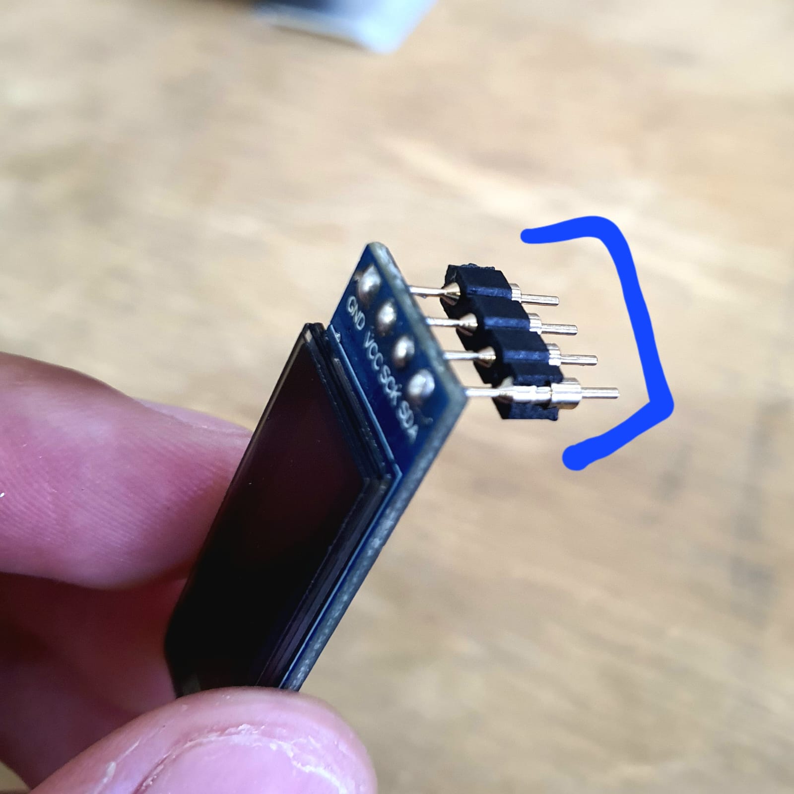
Result
I used the Quentorres for programming the OLED Display. I used a protoboard because the pins on the OLED display I used are originally from a keyboard and the duponts doesn´t fit.
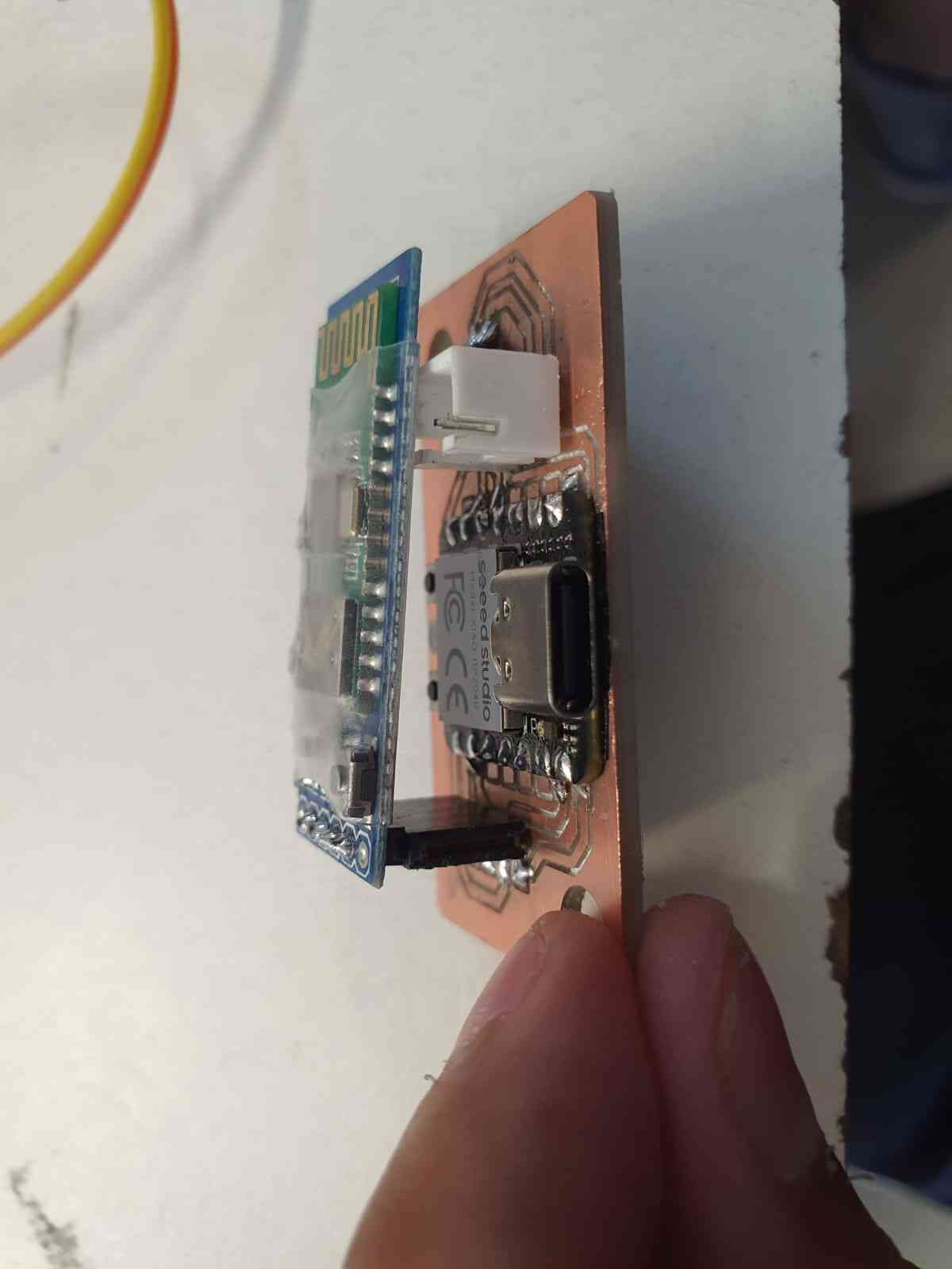
Advance on Final Project
So I need a speaker for my final project so I did one using an H-Bridge.
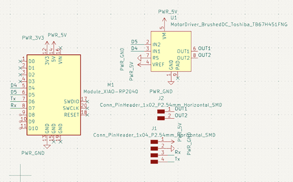
First I designed on KiCad the PCB wich has a XIAO RP2040 and H-Bridge TB67. It has a conection for a Bluetooth
and the output pins for the speaker.
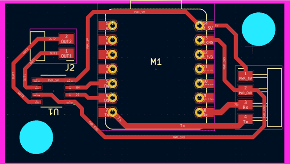
After cutting it and solder it, it look something like this:
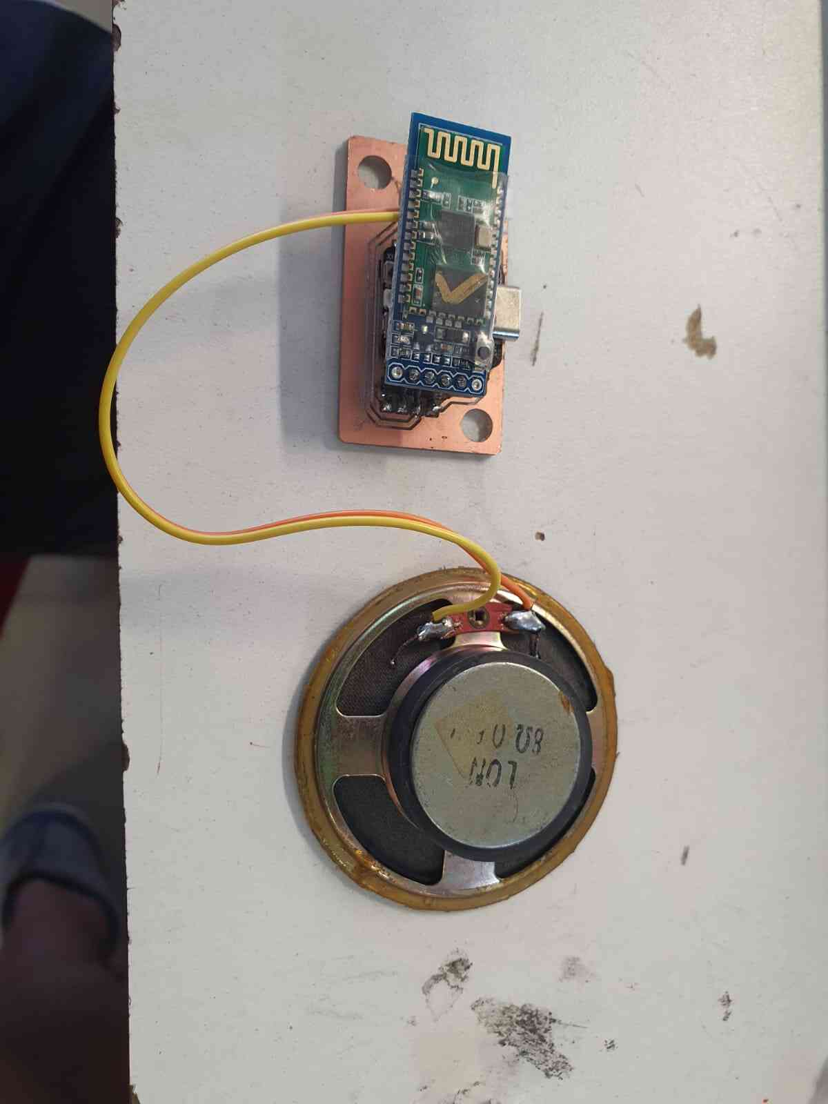
Once we have all conected it sounds something like this via Bluetooth:
Files