11. Input Devices
An input device is a part that provides information, data or control signals to a system, in this case a
microcontroller. For this week I will be using a sensor as an input for my XIAO RP2040 PCB.
Here you can find the Group Site
Sensor
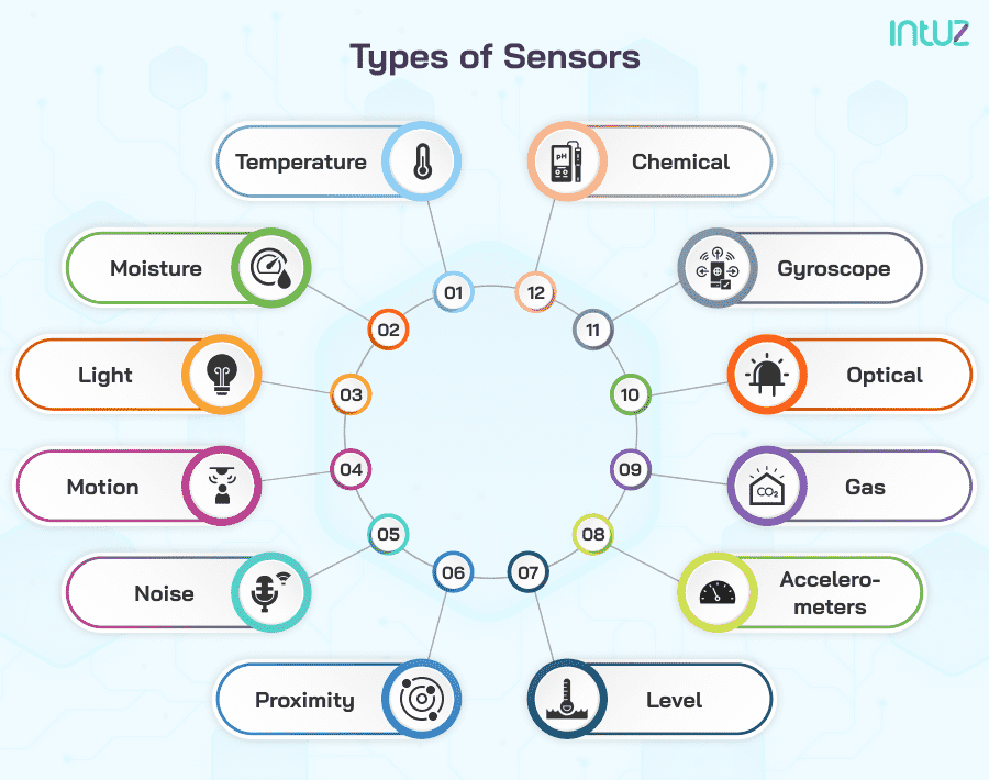
The sensors are input devices that provides an output with relation of a physical quantity.
Device that converts signals from one energy domain to electrical.
There are a lot of different sensors depending on the application you want.
- Types:
- Temperature
- Proximity
- Acceleration
- IR
- Pressure
- Light
- Distance
- Humidity
- Touch
- Strain and weight
For my final project I need to know ifa finger has move (the index one) so I will use the MPU6050 sensor.
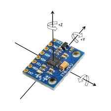
MPU6050
Is a 6 degrees of freedom (DoF) inertial measurement unit (IMU), combining 3 axis accelerometer and gyroscope. It is commonly used for navigation, stabilization or other uses.
The module use I2C for communication (SDA and SCL). Also it has it's own library in arduino. For working you have to make four conecctions: VCC (5V), GND, SCL and SDA.
Design and fabrication
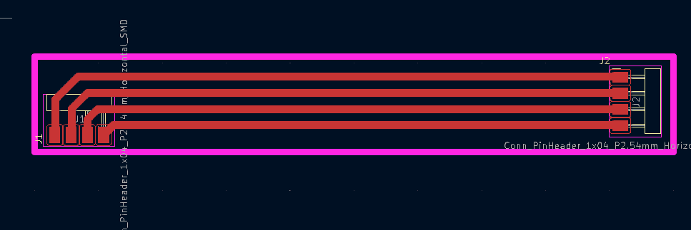
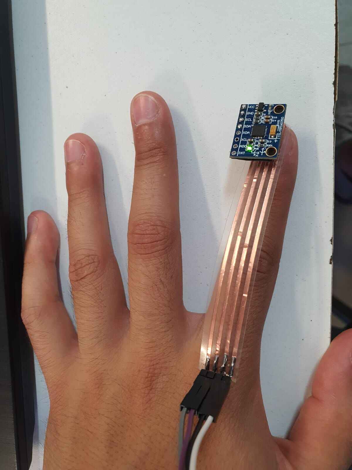
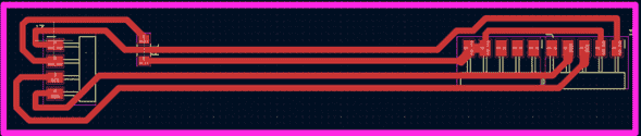
Like the sensor it's going to be on the tip of the index finger and I don't want to use dupont cables I will make a simple PCB with cupper tape as in
week 4. The board will only have the 4 input/output pads to connect the MPU with the XIAO. It is important to have this part flexible to start
making test of how the circuit will be mounted and start thinking about the mecanism to let slide the circuit.
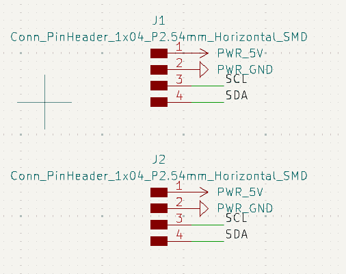
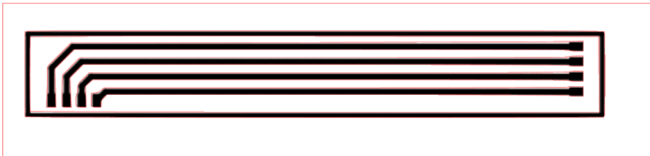
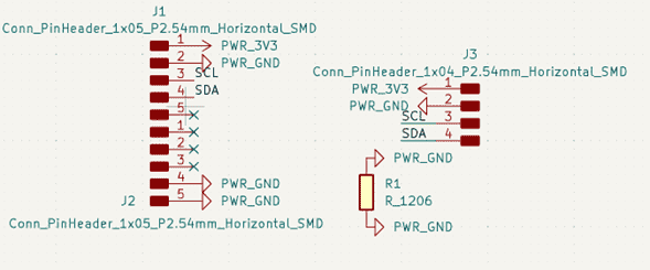
First we add 8 pads in Kicad and name them as 5V, GND, SCL and SDA for both cases, then we can go to the PCB where we arrange them like we want to be. In
this case my finger is 100mm ling and the sensor has to be aligned to my finger for comodity.
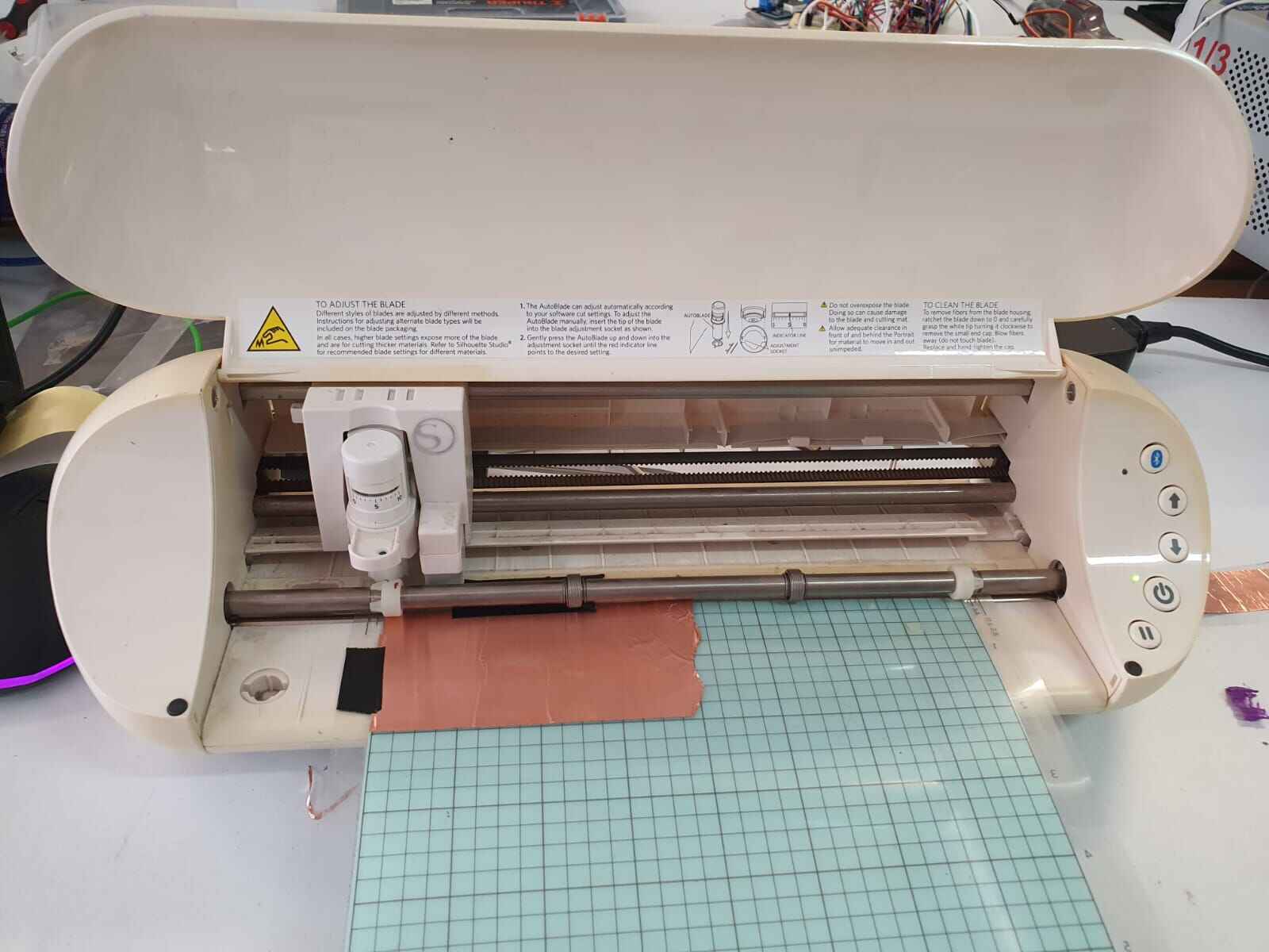
When we got the border and the PCB files in SVG it is important to convert them to PNG using a software online before adding them in Silhouette studio for cupper tape cutting. (Click Here)

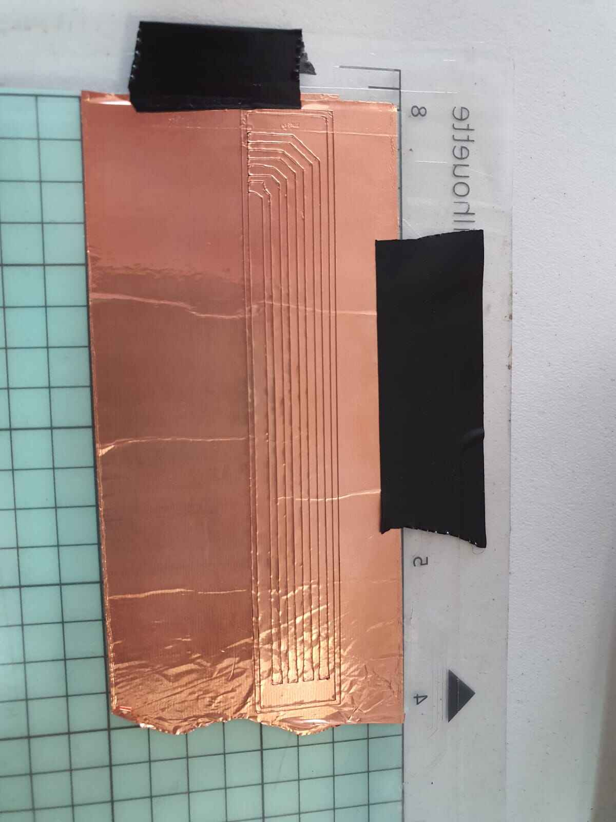
We use the same parameters as Week 4, after getting the cut remove the unwanted parts carefully.
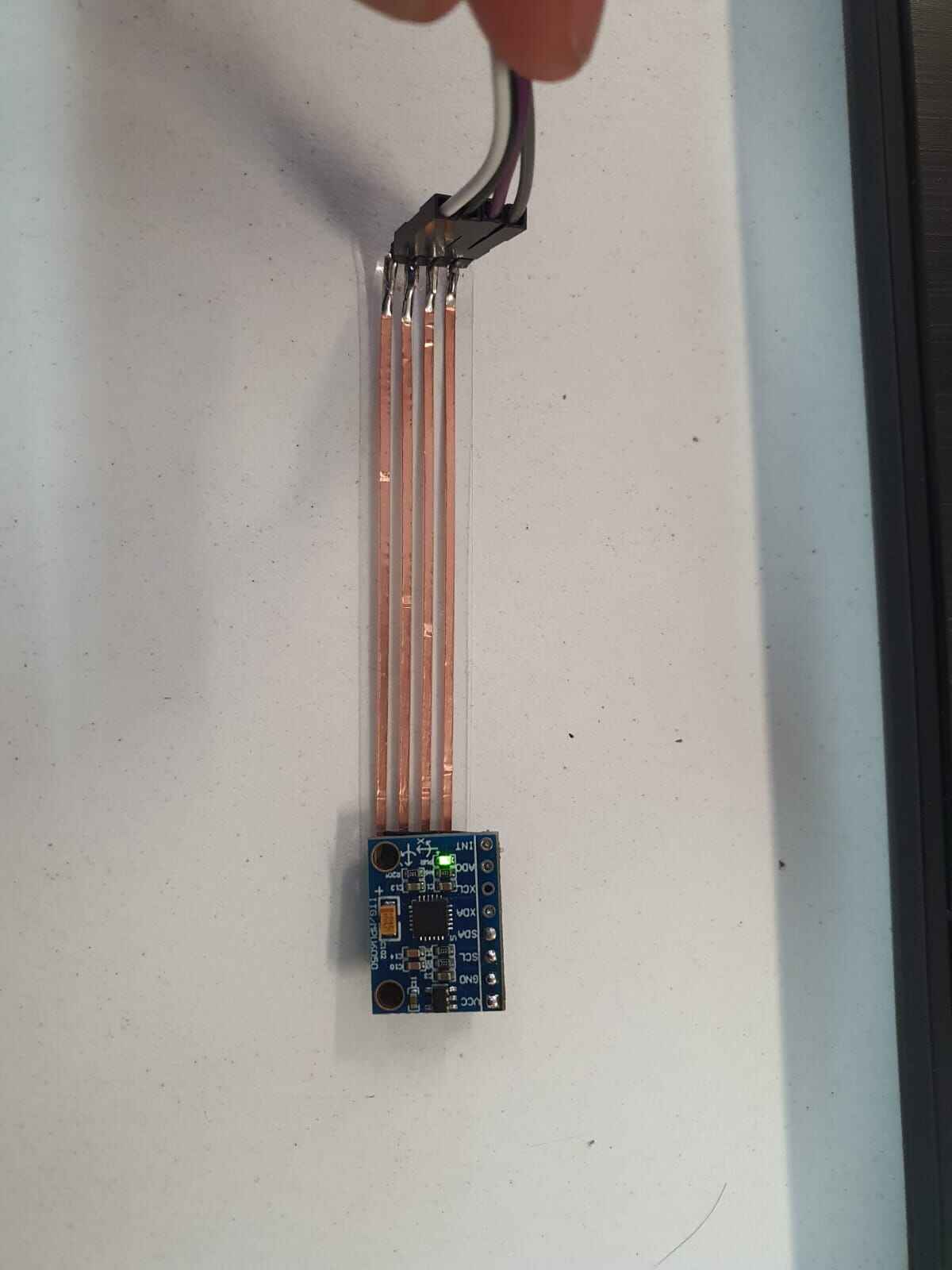
After soldering male pins we can connect the sensor and with dupond cables comunicate it with the XIAO RP2040.
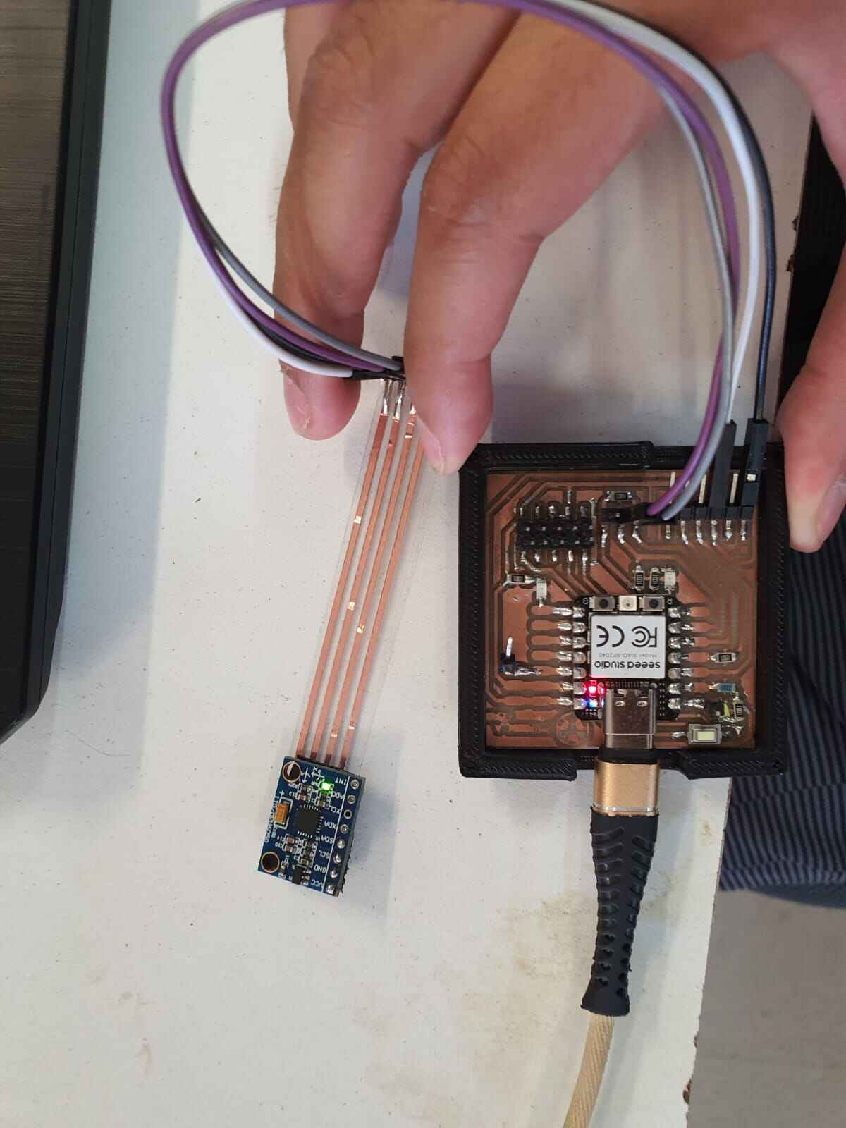
Test and data
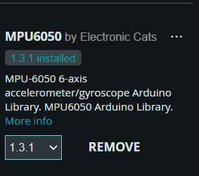
First we have to install different libraries for using it.
- MPU6050
- I2Cdev
- Wire

After installing the libraries we can make the code for reading the acceleration and gyroscope from the sensor.
Code
Full code:
						#include "I2Cdev.h"
						#include "MPU6050.h"
						#include "Wire.h"

						MPU6050 sensor;

						int16_t ax, ay, az;
						int16_t gx, gy, gz;

						void setup() {
						Serial.begin(9600);
						Wire.begin();
						sensor.initialize();

						if (sensor.testConnection())
							Serial.println("Sensor initialized successfully");
						else
							Serial.println("Error initializing the sensor");
						}

						void loop() {
						sensor.getAcceleration(&ax, &ay, &az);
						sensor.getRotation(&gx, &gy, &gz);

						Serial.print("a[x y z] g[x y z]:\t");
						Serial.print(ax); Serial.print("\t");
						Serial.print(ay); Serial.print("\t");
						Serial.print(az); Serial.print("\t");
						Serial.print(gx); Serial.print("\t");
						Serial.print(gy); Serial.print("\t");
						Serial.println(gz);

						delay(1000);
						}
Now let's explain each part for a better understanding.
Libraries
Fist we have to import all the libraries we are going to use:
						#include "I2Cdev.h"
						#include "MPU6050.h"
						#include "Wire.h"
Variables
The we declare the sensor and the variables where the data will be store:
						MPU6050 sensor;

						int16_t ax, ay, az; // Variables to store accelerometer data
						int16_t gx, gy, gz; // Variables to store gyroscope data
Void Setup
In here we initialize de comunication serial, I2C and the sensor. We make a condition to verify that the sensor is connected:
						void setup() {
							Serial.begin(9600);
							// Initialize serial communication
							Wire.begin();
							// Initialize I2C communication
							sensor.initialize();
							// Initialize MPU6050 sensor

							if (sensor.testConnection())
							// Check if the sensor is connected
							  Serial.println("Sensor initialized successfully");
							  // Print message if sensor is connected
							else
							  Serial.println("Error initializing the sensor");
							  // Print error message if sensor is not connected
						  }
Get data
We use the funtion to get the data of the gyroscope and the accelerometer:
						sensor.getAcceleration(&ax, &ay, &az);
						// Read accelerometer data
						sensor.getRotation(&gx, &gy, &gz);
						// Read gyroscope data
Printing
We print a laber of the order of the data with the corresponing acceleration and gyroscope values, and set a delay time between each sample:
						Serial.print("a[x y z] g[x y z]:\t");
						// Print header for data
						Serial.print(ax); Serial.print("\t");
						// Print accelerometer data along x-axis
						Serial.print(ay); Serial.print("\t");
						// Print accelerometer data along y-axis
						Serial.print(az); Serial.print("\t");
						// Print accelerometer data along z-axis
						Serial.print(gx); Serial.print("\t");
						// Print gyroscope data along x-axis
						Serial.print(gy); Serial.print("\t");
						// Print gyroscope data along y-axis
						Serial.println(gz);
						// Print gyroscope data along z-axis

						delay(1000); // Delay for 1 second
Data
Like the ideal practice of this is to be on top of my finger y will mount it above it and watch the results.
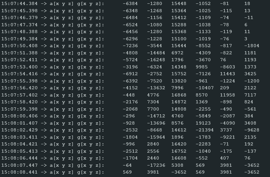
After running the code and making some flex movement of the finger I got this data:
Opinions for the final project
First
After getting the sensor in one finger I realized I need a way to hold it to the knuckle for prevent of moving, also
I need a rail or something in the glove to prevent horizontal movements as well as a bridge that let the pcb slide when the
finger moves because it changes it's lenght.
Second
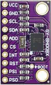
The lectures of the sensor aren't very precise when I don't move my hand it start changing it's value. So I found another sensor
that can help me with this problem because it has a 9 DoF, it add a 3 axis magnometer to prevent moving when holding it still, the
BNO08x.
Flex sensor
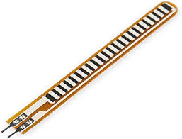
Also for detecting if the other fingers are flex or straight I used flex sensors. I attach them to my finger using
tubular mesh.
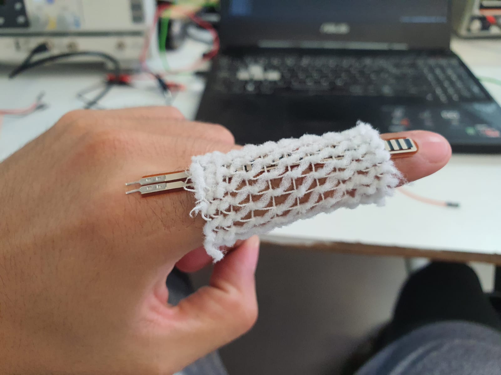
After using a voltage divider we get an output from 2.9 volts (straight) to 1.5 volts (max flex). Using a osciloscope we can see some noise so in the final project I will be using a Wheatstone bridge to reduce the noise and maybe a differential amplifier too.
Lets add the flex sensors and the Gyro
For my final project I need to reed the value from these different sensors, so lets make it, first the PCB:
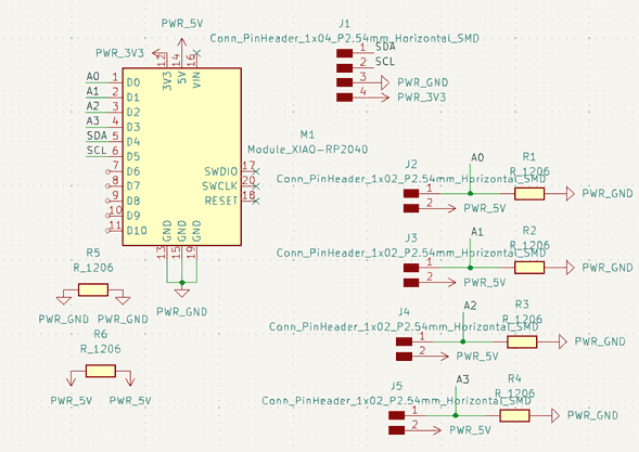
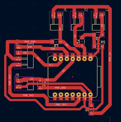
The assembly is very easy, you can check it on the final project.
Once we can conect it by serial to the PC and graph all the values by doing different sings.