15. Wildcard Week
On this Wildcard Week we need to make something new, that the plan doesn't cover in the other assignement. Definitions generated by ChatGPT.
Machine Learning
Machine Learning (ML) is a part of AI that focus on machines learning patterns and make their own decisions without a lot of programming.
Tiny ML
The difference with TinyML and ML is the deployment of the model on devices with limited computational resources (microcontrollers). Having limits in power, memory, processing capabilities, etc.
Edge Impulse
It is a platform to develop machine learningn models.
- Platform: For building, training and deploying models for edge devices (XIAO Sense). With a friendly interface to label, collect, preprocess, data. Used for devices for audio, image, sensors, accelerometer, etc.
- Features: Collect and label sensro data from devices with different algorithms and neural networks for their models. They can be upload to an edge device once trained.
- Applications: Used for IoT applications, anomaly dettections. environmental monitoring, gesture recognition, etc.
Getting Started
All the information is on the MOtion Recognition SEEED STUDIO webpage (Click Here).
Before we start with everything it is important to create an Account
on Edge Impulse (Click Here).
After having a profile we can start with training a model.
Step 1
Installing Libraries
First we need the Seeed Arduino LSMDS3 Library.
After, for set the XIAO on edge impulse we need:
- Node.js
- Arduino CLI For CLI open the serial monitor and run:
npm install -g edge-impulse-cli
Step 2
Edge Impulse
Create a new project on Edge Impulse and connect the XIAO into the computer.
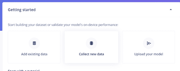
Click on Collect New Data.
Step 3
Get Data
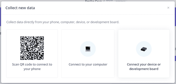
When clicking on collect new data there are 3 available options: Scan Qr, from your computer or device/developement board.
Click on the third option.
Step 4
Accelerometer data
Here we have to upload the first XIAO Code (Above) for sending the parameters we want, in this case: Acceleration (x,y,z).
The library link is on the first step (LSM6DS3).
Code
						#include "LSM6DS3.h"
						#include "Wire.h"

						//Create a instance of class LSM6DS3
						LSM6DS3 myIMU(I2C_MODE, 0x6A);  //I2C device address 0x6A

						#define CONVERT_G_TO_MS2 9.80665f
						#define FREQUENCY_HZ 50
						#define INTERVAL_MS (1000 / (FREQUENCY_HZ + 1))

						static unsigned long last_interval_ms = 0;

						void setup() {
						Serial.begin(115200);
						while (!Serial)
							;

						if (myIMU.begin() != 0) {
							Serial.println("Device error");
						} else {
							Serial.println("Device OK!");
						}
						}

						void loop() {
						if (millis() > last_interval_ms + INTERVAL_MS) {
							last_interval_ms = millis();
							Serial.print(myIMU.readFloatAccelX() * CONVERT_G_TO_MS2, 4);
							Serial.print('\t');
							Serial.print(myIMU.readFloatAccelY() * CONVERT_G_TO_MS2, 4);
							Serial.print('\t');
							Serial.println(myIMU.readFloatAccelZ() * CONVERT_G_TO_MS2, 4);
						}
						}
If you run the code and open the serial monitor it will show the data we will be sending.
Step 5
Send data
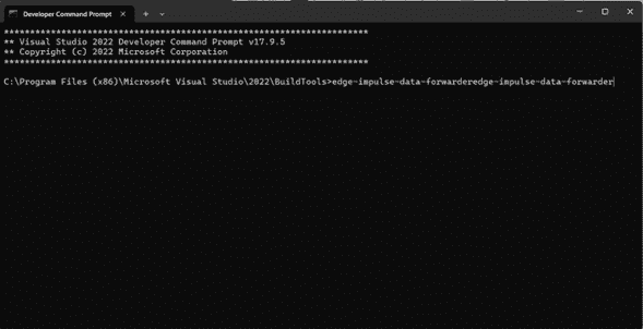
For sending the data to Edge impulse we need to open the terminal CLI or cmd and run:
edge-impulse-data-forwarder
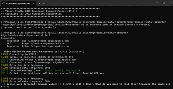
In case it is your second time creating a model or it appears an error of connecting with API, try this line:
edge-impulse-data-forwarder -clean
Login
You will need to login your account and project. It will appear different COMs options (choose the one of the XIAO). it will tun a test an return some values, you will have to name them separate with comas ",". Finally give the device a name.

Step 6
Connect with Impulse
On data acquisition you can select the device (Previously named) on the right of the page.
Step 7
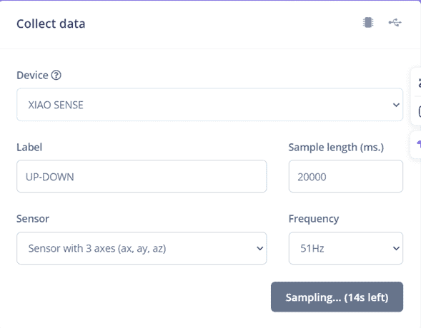
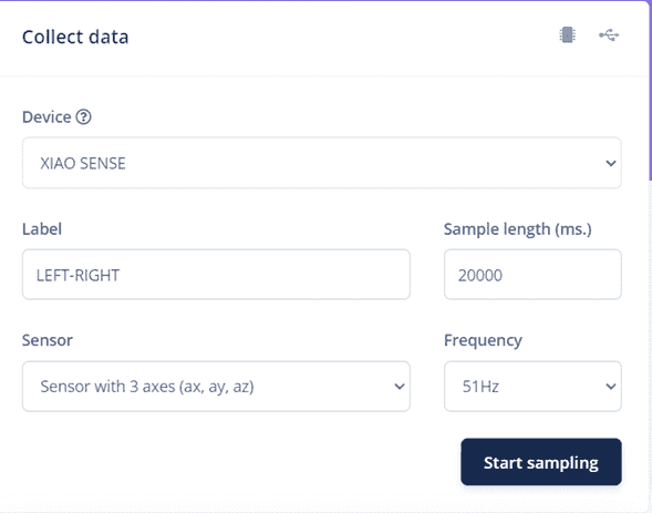
Start Sampling
On the Record new data window we can select the device, label (name of the data), wich parameters, sample lenght (ms) and frequency.
First we will start with an Up-down motion for 20000 ms of sampling.
It will start a countdown wherw you have to make a repeatly movement (Up-down).
Step 8
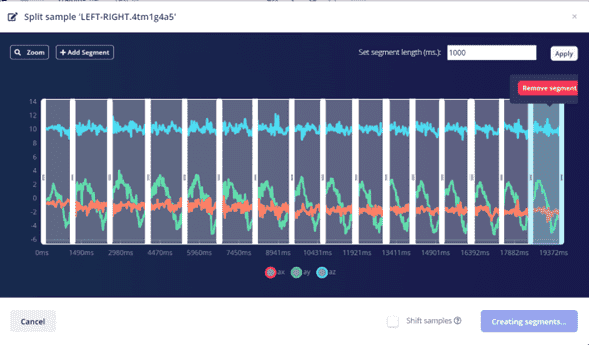
Split Data
After the 20 seconds a graph will be shown below, with the movement of the 3 axis.
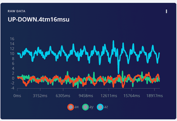
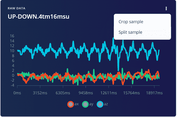
By clicking on the three dots > Split data.
We have an aplified graph where we add segments and locate them where we want to detect.
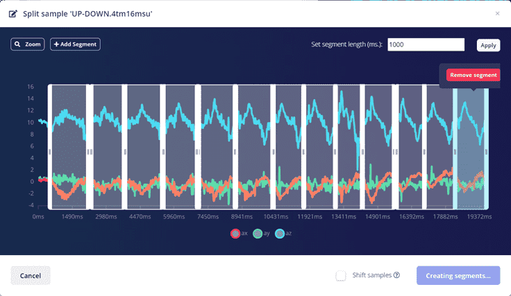
When done, Click on Split
Step 9
Repeat
We will repeat the previous step for another movement (Left-right).
Step 10
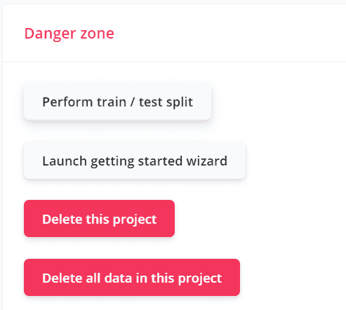
Perform Train
Click on Dashboard > Drop down the page click on Perform train.
Step 11
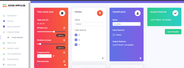
Save Impulse
Navigate to Impulse Design > Add a processing block > Add Learning Block > Add Classification > Save Impulse.
Step 12
Save Parameters
Click on Flatten > Scroll Down > Click on Save Parameters
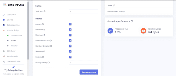
Step 13
Freatures
On Spectral featyres > Down on the page > Generate features
Step 14
Train for Output
Click on the Classifier > Start training (Unoptimized[float32])
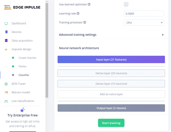
In there it shoes the precision of the model, in case you want to change by adding more data (LOW is less than "65%"").
Step 15
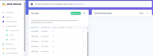
Model Testing
Scroll down the left bar and Click on Model training and Classify All
Step 16
Arduino Library
Now we have to create and add an Arduino Library with the model.
Click Deployment > Select Arduino Library > Build
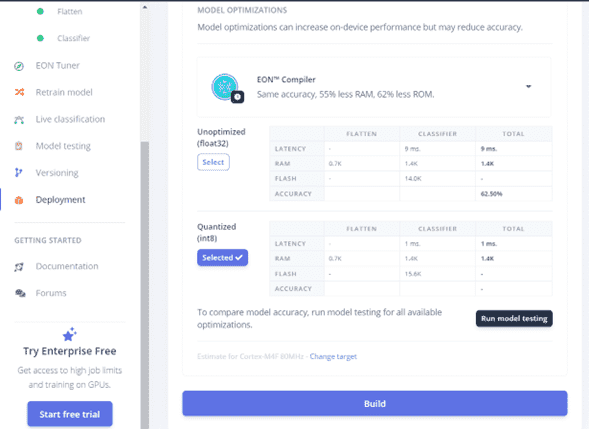
This will download a .zip file that you have to install as same as all the other libraries.

It is important to change the name because this is the way you will use it in the code.

Code
						/* Includes */
						#include gg_inferencing.h
						#include LSM6DS3.h
						#include Wire.h
						/* Constant defines  */
						#define CONVERT_G_TO_MS2    9.80665f
						#define MAX_ACCEPTED_RANGE  2.0f

						/* Private variables  */
						static bool debug_nn = false;
						LSM6DS3 myIMU(I2C_MODE, 0x6A);

						const int RED_ledPin =  11;
						const int BLUE_ledPin =  12;

						void setup()
						{
							// put your setup code here, to run once:
							Serial.begin(115200);
							Serial.println("Edge Impulse Inferencing Demo");

							//if (!IMU.begin()) {
							if (!myIMU.begin()) {
								ei_printf("Failed to initialize IMU!\r\n");
							}
							else {
								ei_printf("IMU initialized\r\n");
							}

							if (EI_CLASSIFIER_RAW_SAMPLES_PER_FRAME != 3) {
								ei_printf("ERR: EI_CLASSIFIER_RAW_SAMPLES_PER_FRAME
								should be equal to 3 (the 3 sensor axes)\n");
								return;
							}
						}

						float ei_get_sign(float number) {
							return (number >= 0.0) ? 1.0 : -1.0;
						}

						void loop()
						{
							uint8_t buf2[64]="left&right";
							uint8_t buf3[64]="up&down";

							ei_printf("\nStarting inferencing in 2 seconds...\n");

							delay(2000);

							ei_printf("Sampling...\n");

							// Allocate a buffer here for the values we'll read from the IMU
							float buffer[EI_CLASSIFIER_DSP_INPUT_FRAME_SIZE] = { 0 };

							for (size_t ix = 0; ix < EI_CLASSIFIER_DSP_INPUT_FRAME_SIZE; ix += 3) {
								// Determine the next tick (and then sleep later)
								uint64_t next_tick = micros() + (EI_CLASSIFIER_INTERVAL_MS * 1000);

						buffer[ix] = myIMU.readFloatAccelX();
						buffer[ix+1] = myIMU.readFloatAccelY();
						buffer[ix+2] = myIMU.readFloatAccelZ();

						//buffer[ix] = myIMU.readFloatGyroX();
						//buffer[ix+1] = myIMU.readFloatGyroY();
						//buffer[ix+2] = myIMU.readFloatGyroZ();

								for (int i = 0; i < 3; i++) {
									if (fabs(buffer[ix + i]) > MAX_ACCEPTED_RANGE) {
										buffer[ix + i] = ei_get_sign(buffer[ix + i])
										* MAX_ACCEPTED_RANGE;
									}
								}

								buffer[ix + 0] *= CONVERT_G_TO_MS2;
								buffer[ix + 1] *= CONVERT_G_TO_MS2;
								buffer[ix + 2] *= CONVERT_G_TO_MS2;

								delayMicroseconds(next_tick - micros());
							}

							// Turn the raw buffer in a signal which we can the classify
							signal_t signal;
							int err = numpy::signal_from_buffer(buffer,
							EI_CLASSIFIER_DSP_INPUT_FRAME_SIZE, &signal);
							if (err != 0) {
								ei_printf("Failed to create signal from buffer (%d)\n", err);
								return;
							}

							// Run the classifier
							ei_impulse_result_t result = { 0 };

							err = run_classifier(&signal, &result, debug_nn);
							if (err != EI_IMPULSE_OK) {
								ei_printf("ERR: Failed to run classifier (%d)\n", err);
								return;
							}

							// print the predictions
							ei_printf("Predictions ");
							ei_printf("(DSP: %d ms., Classification: %d ms., Anomaly: %d ms.)",
								result.timing.dsp, result.timing.classification, result.timing.anomaly);
							ei_printf(": \n");
							for (size_t ix = 0; ix < EI_CLASSIFIER_LABEL_COUNT; ix++) {
								ei_printf("%s: %.5f\n", result.classification[ix].label,
								result.classification[ix].value);
							}
						#if EI_CLASSIFIER_HAS_ANOMALY == 1
							ei_printf("    anomaly score: %.3f\n", result.anomaly);
						#endif

						if (result.classification[1].value > 0.5) {
							digitalWrite(RED_ledPin, LOW);
							digitalWrite(BLUE_ledPin, HIGH);   // updown red
							delay(2000);
						}

						if (result.classification[0].value > 0.5) {
							digitalWrite(RED_ledPin, HIGH); //left&right blue
							digitalWrite(BLUE_ledPin, LOW);
							delay(2000);
						}
						}
Final
After adding the code and oppening the serial monitor we got this output.
Files