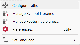
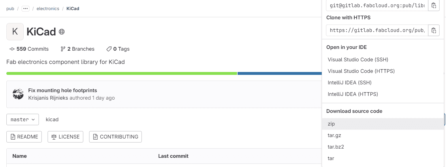
8. Electronics Design

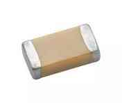
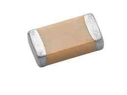
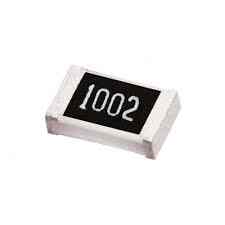
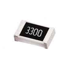
Electronic circuit designing involves the selections and interconnections of physical devices, for different purposes. It is important to define the requirements that you are going to use such as: resistors, capacitors, buttons, leds, voltage regulator and one of the most important things the microcontroler (brain).
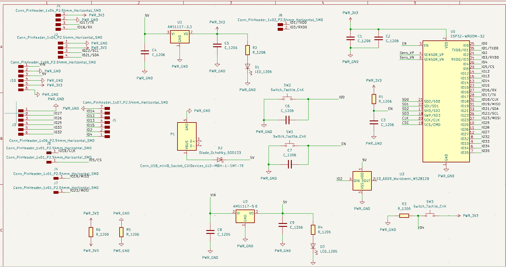
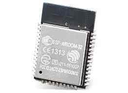
For this week assignment I will be creating my own pcb using Kicad and an ESP32-wroom32.

Group Site

If you want to read the Group Page, Click Here.
For this group assignement we had to test different equipment to know more about electronics and a microcontroler operation.

    Equipment (hover for more info):
  • Developement Board

  • There are different microcontrolers boards depending on the project your making. The most common ones are: Arduino, RaspberryPi, ESP32, PIC, etc.

  • Power Supply
  • A power supply it is used to power up the circuits you build, depending on you requierements AC or DC.

  • Multimeter
  • It is used for meassuring voltage, current, resistance, capacitance, continuity, etc. Basically is a test tool to meassure different values. You can change it mode by switching the dial to its position and verify the input jacks.
    Voltage

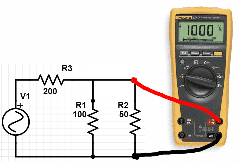
    If you want to meassure Voltage verify the dial is in V (DC or AC) and connect it in parallel in the part you want.
    Current

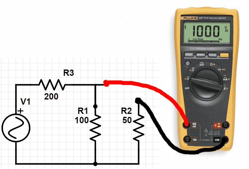
    For current change the dial to A and the input jack. For meassuring you have to open the circuit and make a series conection.
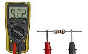
    Resistance/Capacitance
    In the case of resistance and capacitance when you dont know the value you only have to touch it with the 2 probes.

  • In Resistance it will give the value in Ohms and a prefix
  • For Capacitance it will give the value in Farad and a prefix

  • Continuity
    The same thing as resitance but instead of giving you a value it will emit a beep when the circuit is closed.

  • Oscilloscope
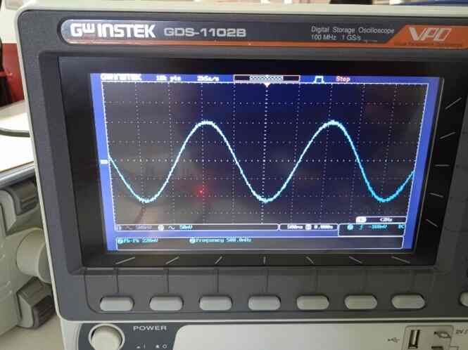
  • It is used to visualize/analyze the behavior of the electronic signals. Commonly used for fixing mistakes, debugging and check the signal integrity.

  • Function Generator
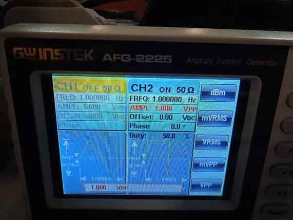
  • It produces different type of waveforms (sine, square, triangle), used to test different signals conditions.

  • Documentation

  • One of the most important parts of the components is the datasheet, in here you can find the lenght of the components, voltage, current, schematics and everything you need for designing your circuits.


    Let's try out with some test
    For this part I will make a sampling on a digital system for later obtain the original signal.
    For using most of the equipment from above I will use an arduino to obtain an analog reading (wave sign) from the function generator in the Pin A0 in an Arduino. Make a vector to store data. Send them to matlab by serial port to generate the graph in the oscilloscope.

    Code in arduino
    
    						
    						const int analogInPin = A0;  
    						int k=49;    // Number of samples 
    						int sensorValue[50];   // Vector to storage data
    						int i;
    						unsigned long ts = 2.5;      // Sample time mseg
    						unsigned long TiempoAhora = 0;
    
    						//sensorValue = 0;        // value read
    
    						void setup() {
    						// initialize serial communications at 9600 bps:
    						Serial.begin(9600);
    						}
    
    						void loop() {
    						for(i=1;i < =k;i++){
    						TiempoAhora = millis();
    						sensorValue[i] = analogRead(analogInPin);
    						// wait n milliseconds before the next loop for the analog-to-digital
    						// converter to settle after the last reading:
    						while(millis() < TiempoAhora+ts){
    							// espere ts milisegundos
    							}
    						}
    						// print the results to the Serial Monitor:
    						for(i=1;i < =k;i++){
    						Serial.println(sensorValue[i]);
    						delay(5);
    						}
    						Serial.end();
    						}


    Code in MatLab
    
    						function Matlab_Arduino(~)
     
    						% Matlab + Arduino Serial Port communication
    						
    						close all;
    						clc;
    						frecuencia = 50;
    						periodo=1.0/frecuencia;
    						numero_muestras=40;
    						% Se tomaran 20 muestras por ciclo de la señal se graficaran 2 ciclos
    						% Total de muestras 40
    						% Con un tiempo de muestreo del Arduino cada 
    						delay_arduino=2*periodo/numero_muestras;
    						
    						y=zeros(1,numero_muestras); %Vector donde se guardarán los datos
    						x=(0 : 1: numero_muestras-1)*delay_arduino;
    						t=delay_arduino*(0:1:numero_muestras-1);
    						disp('fijar delay de arduino');
    						disp(delay_arduino*1000);
    						z=input('listo ???');
    						
    						%Inicializo el puerto serial que se utilizará
    						delete(instrfind({'Port'},{'COM5'}));
    						puerto_serial=serial('COM5');
    						puerto_serial.BaudRate=9600;
    						warning('off','MATLAB:serial:fscanf:unsuccessfulRead');
    						%Abro el puerto serial
    						fopen(puerto_serial); 
    						
    						%Declaro un contador del número de muestras ya tomadas
    						contador_muestras=1;
    						ylim([0 5.1]); 
    						xlim([0 numero_muestras]);
    						
    						%Bucle while para que tome y dibuje las muestras que queremos
    						
    						while contador_muestras < =numero_muestras
    								valor_potenciometro=fscanf(puerto_serial,'%d')';
    								y(contador_muestras)=(valor_potenciometro(1))*5/1024;      
    								contador_muestras=contador_muestras+1;
    						end
    						%plot(x,y);
    						plot(x,y,'-o');
    						grid on;
    						figure;
    						sig=2.5*sin(2*pi*frecuencia*t)+2.5;
    						%plot(t,sig);
    						plot(t,sig,'-o');
    						grid on;
    						
    						%Cierro la conexión con el puerto serial y elimino las variables
    						fclose(puerto_serial); 
    						delete(puerto_serial);
    						clear all;
    						
    						end


    Designing

    There are different softwres for designing circuits such as:

  • EasyEDA
  • Altium
  • KiCad
  • Fusion360

  • As I mention before I will be using KiCad. When you open it you find this main page where you can create a new project, open schematics, etc.
    For the use of ESP32-wroom32 is used for base this ESP schematic.
    My board wil have out pins for any use in the future, as well as power pins (+5v, 3.3v and ground) y also group some of the most common pins as power, I2C, UART, for testing adding a Neopixel and a button.
    First it is important to install the library and footprints of the components we have available in FabLab Puebla.

    Steps to add library

    Download libraries


    CMA1200

      Steps:
  • Download the file
  • Decompress the file
  • Open Symbol Library


    CMA1200

  • Create an empty row
  • Name it with fab
  • Link the path to the fab.kicad_sym
  • Open Footprint Library


    CMA1080

  • Create an empty row
  • Name it fab
  • Link it to fab.pretty
  • Configure Paths


    CMA1080

  • Create an empty row
  • Name it FAB
  • Link it to the complete file
  •      

    Schematic

    Interface


    CMA1200

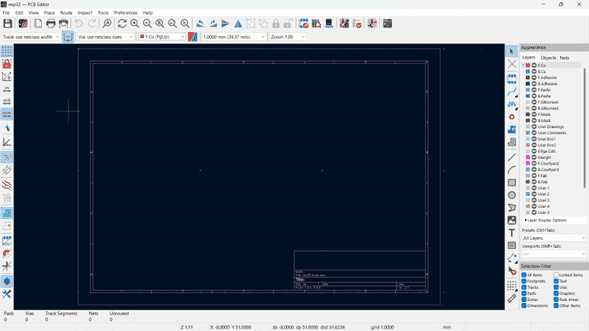
    First we can se the work frame where we can add the components and its conections.
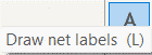
    On the right bar are all the components, wire, labels, text, all you need for your Schematic.
    And some more options on the top bar as: creating a PCB, zoom, mirror, rotation, etc.

    Symbols/Shortcuts


    CMA1200

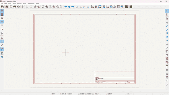
    In all the left side bar we can add items by clicking them or using its shortcut.

      Shortcuts:
  • Add Symbols (A): all the components (try to find fab library for footprint).
  • Add Power Symbols (P): such as ground and different voltages.
  • Add a Wire (W): to connect components.
  • Draw Net Labels (L): to reduce wires and a cleaner view.
  • Draw Text (T): if you want to add a note.
  • No Conection Flags (Q): for pins that have no conection.
  • Components


    CMA1080

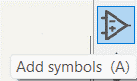
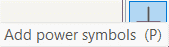
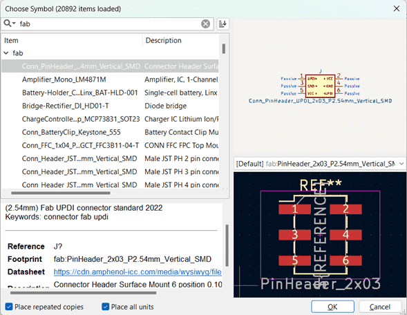
    By clicking A or the button it will appear the window where you can find all the components schematics, footprint, component name and datasheet.
    *Note: It is importantto verify the footprint of your component.*
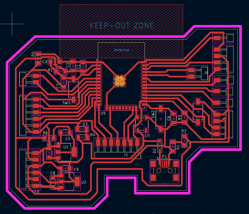
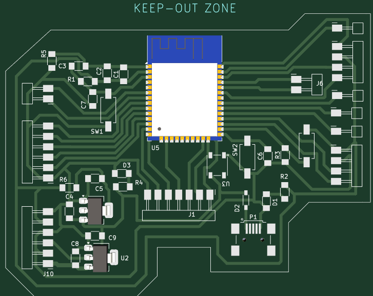
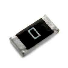
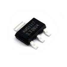
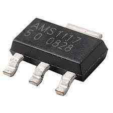
    Components I use

      List:
  • ESP32-wroom32
  • LED
  • Resistor
  • Capacitor
  • Push Button
  • Pin Headers
  • Schottky Diode
  • Mini USB Socket
  • Voltage Regulator
  • Neopixel
  • Rules


    CMA1080

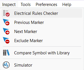
    On the navigation bar -> Inspect -> Electical Rules Checker -> Run ERC
    Here you can find all you mistakes on your conections, design, power supplies, etc.

    Final


    So in my PCB I start adding the microcontroler I will use, in this case is the ESP32-wroom32, after that I investigated about the output pins, wich ones can I use, boot, reset, etc. Having on base this schematic. Afet knowing all the pins, I started by adding the buttons, resistors and capacitors. For testing my board I add a Neopixel and a button to make some actions. Finally we can add our pin headers for comunicating to other future devices. I joint the most common ones together such as I2C, UART, Programing and Power. In the case of the power I added a +5v of input in case of external battery with 2 voltage regulators to (5v and 3.3v).
    CMA1080
    If you don't have mistakes or the mistakes/warrnings don't affect your designing like ports not connected or something else, you can continue by routing all the PCB and giving it the final shape. On the top bar you find the Open Board to start.


    PCB
    Once you're creating a new PCB it appears this window:
      Steps:
  • Add your schematics footprints by clicking update on the top side
  • Place all the components on a convenient way
  • Change the board setup (clearance and width) depending on the current it will send
  • Change the track width on the top left, depending the power it holds
  • Route all the tracks
  • Change of layer to mask and create a 1mm border (any shape)


  • By adding all the components the software makes and invisible autowire (green), this shows where you have to connect everything. First I started to make this lines straigh to the pins of the esp, so having the esp on the center of the board is the most optimal in this case. I always added the capacitor, led and resistor to his button like a single package. Lastly I put the pin headers on the border.
    For the wire I choose a clearance of 0.4 and a track width of 0.5. This rules is fot the current that the board will support, I use 0.7 for data, 3.3v and ground. And for the +5v of input I put a 1mm track width.
    For the border I use 1mm because the tool was of this diameter so for the software (mods) to generate the contourn correctly it cas to fit in.

    Once all is complete we got the final PCB design after many attempts.
    3D perspective
    Once you have done all the conections you can preview a 3D image of your Board to see how it will finally look.

    Export
    We have to export it as an SVG
  • File
  • Export
  • Firts F.Cu layer
  • Then Mask layer


  • Once we have the both files we can upload them into mods to get de .rml for the Roland milling machine.


    Fabrication

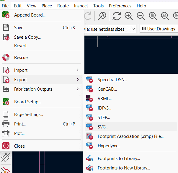
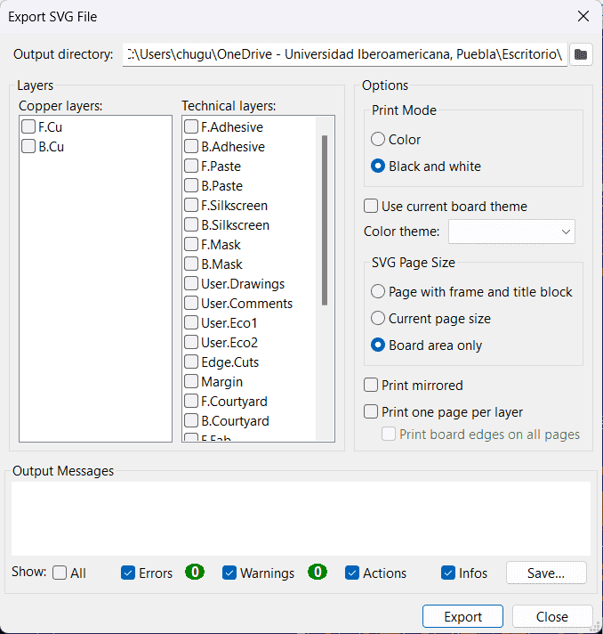
    In this case instead of uploading a png file, right on top we upload the SVG format.
    We modify the same parameters of milling and cutting, in my case I will lower the speed to 3 mm/s, 2 offset and a tool diameter of 0.3 mm. I change this because some of my components have smaller paths.
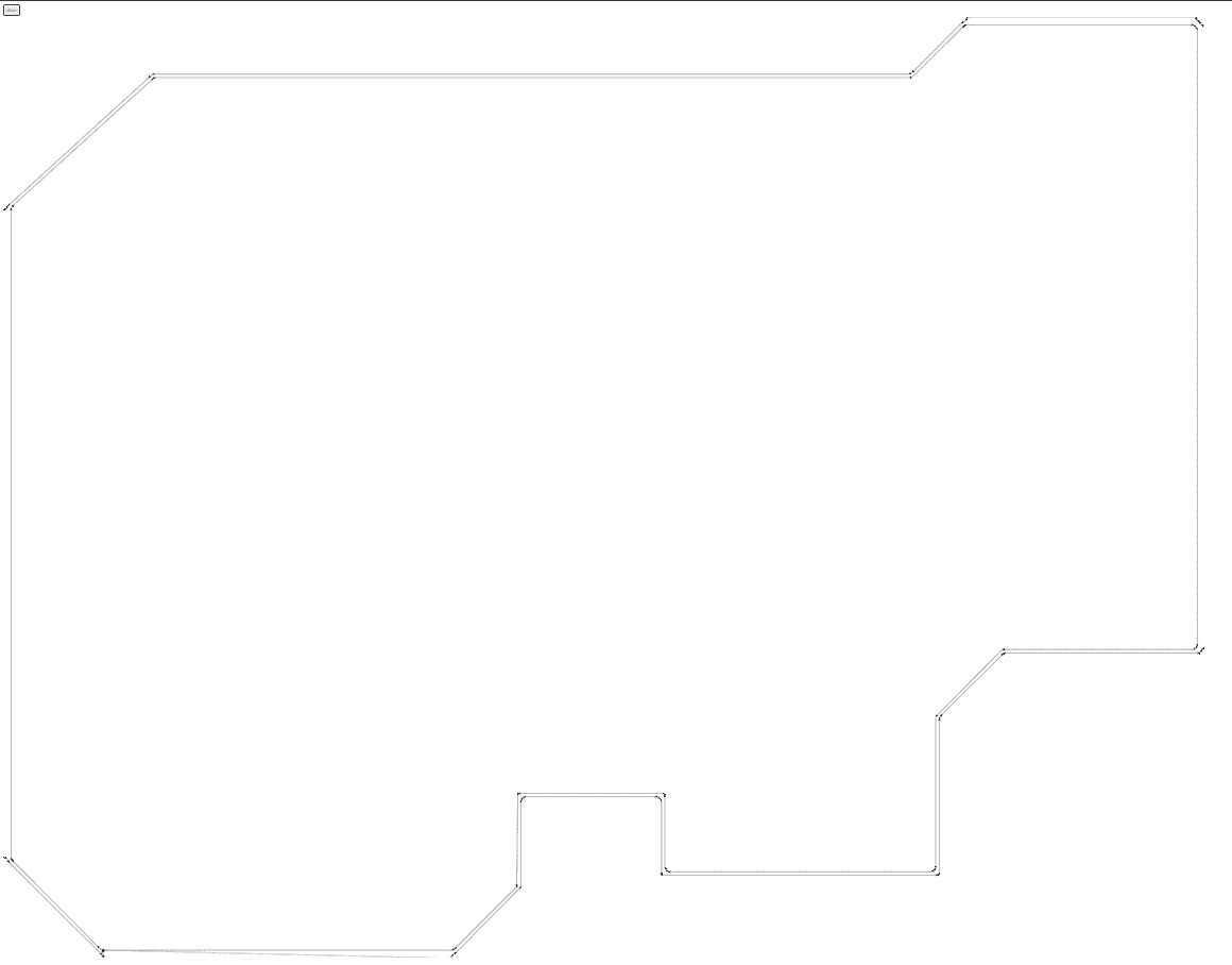
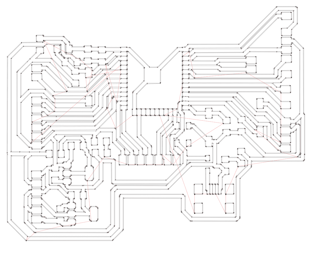
    Having this 2 different files for milling and cutting.


    Case

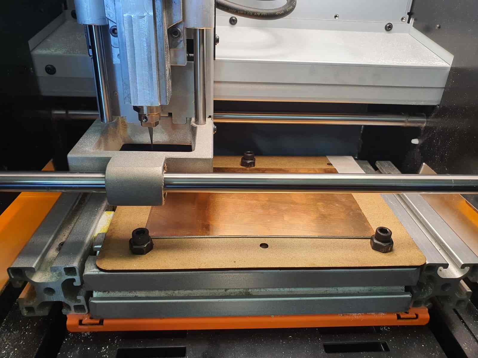
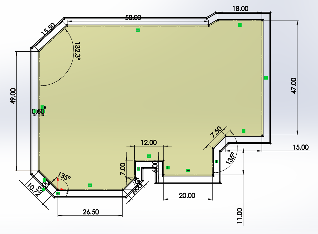
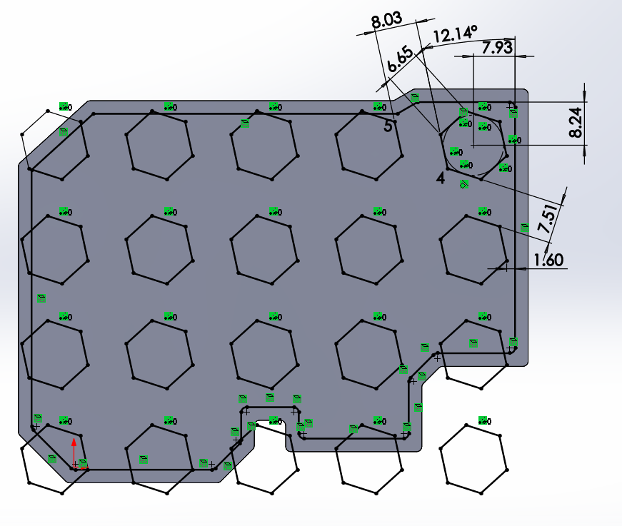
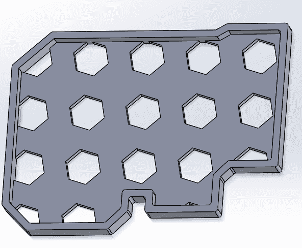
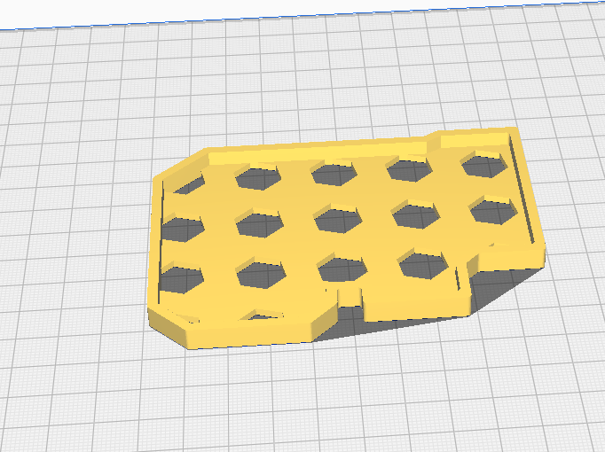
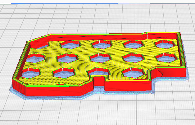
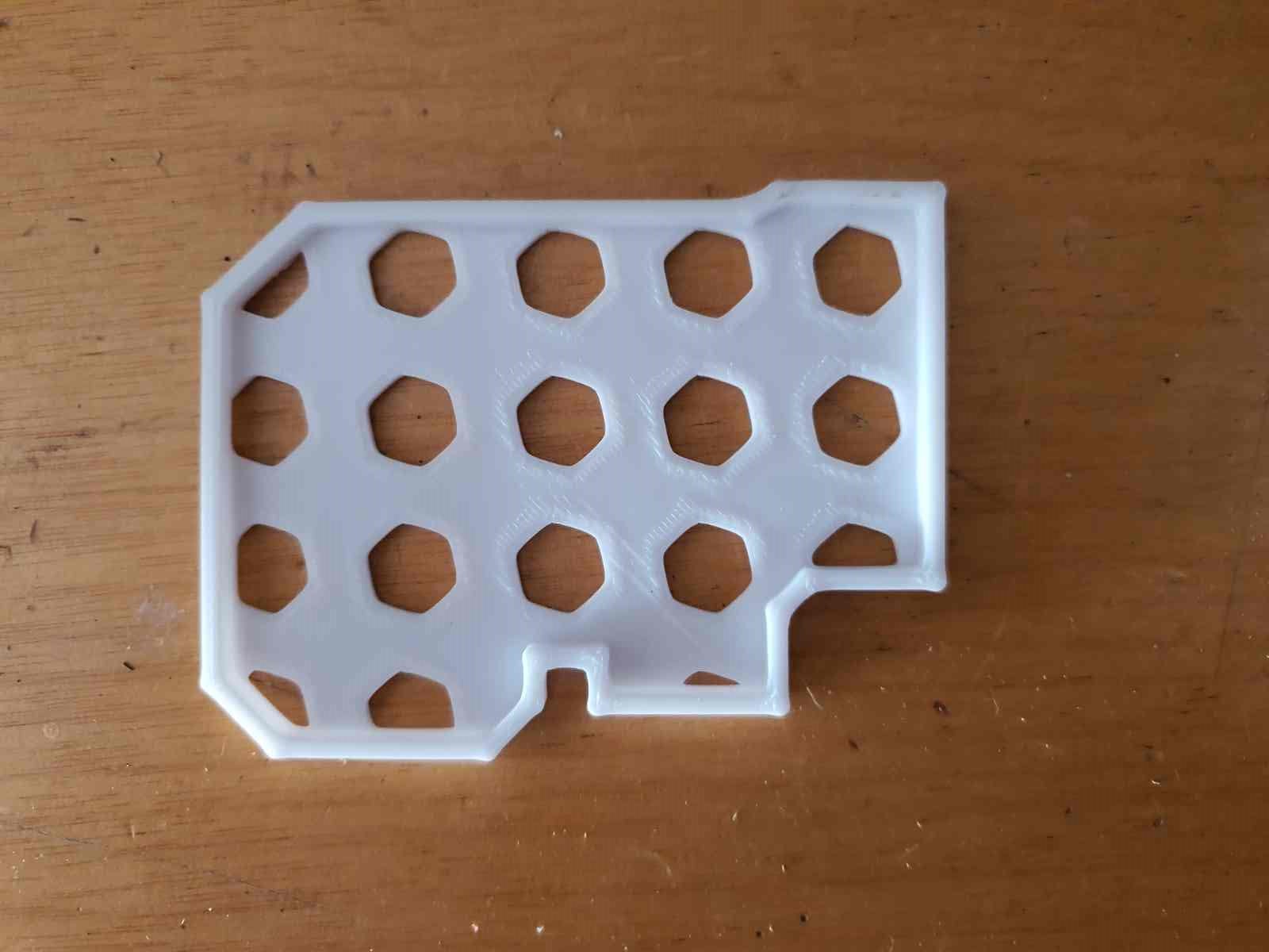
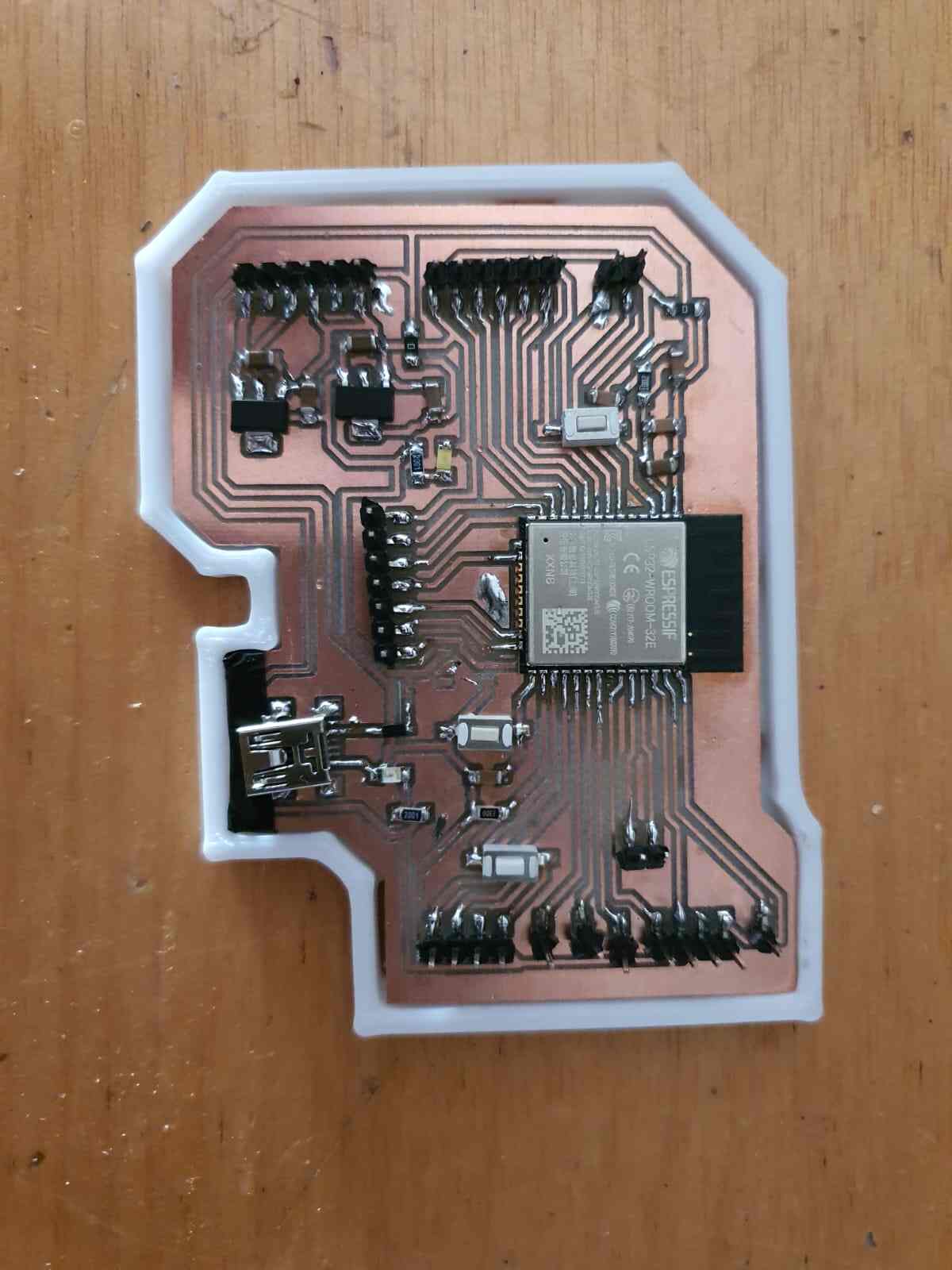
    For creating a case to the new PCB made I used Solidworks for the design, Cura for getting the g-code and print it in an Ender.

      Steps:
  • Create a new sketch
  • Draw the board profile
  • Create a new contour 0.5mm away for the PLA expansion
  • Add another border
  • Make a first path for the base
  • Make a second path fot the border
  • Round all the corners
  • Open a new sketch and create and hexagon pattern
  • Cut extrude the pattern


  • Slicing in cura
    Like we dont care about the resistance we only give a 8% of infill gyroid with Raft adhesion.

    Final case


    Soldering

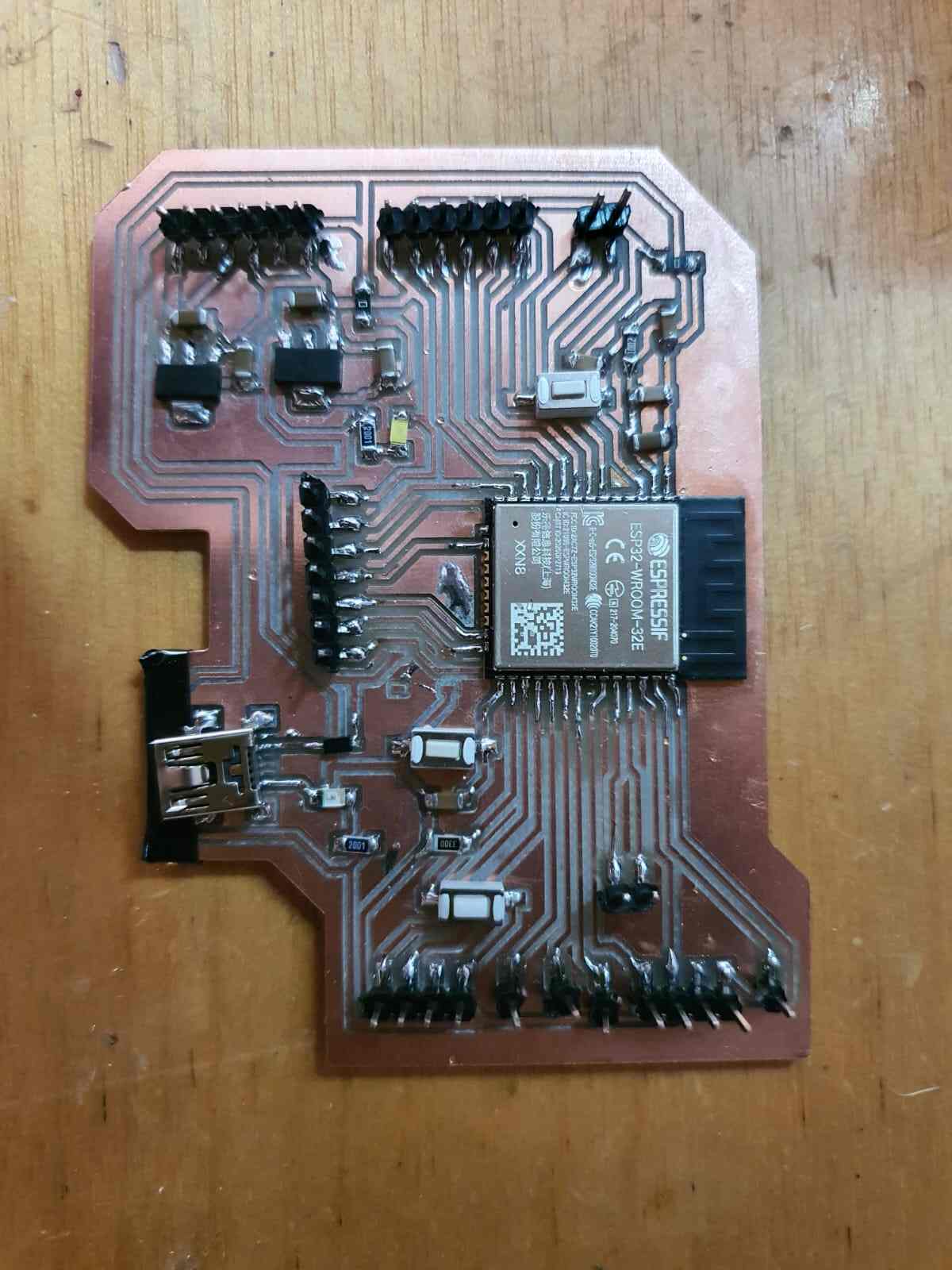
    For soldering the firt thing to do was getting all the components.

      Components (hover to see them):
  • ESP32-wroom32
  • 0.1 uF capacitor (4)
  • 10 uF capacitor (5)
  • 10 K resistor (1)
  • 2 K resistor (2)
  • 330 resistor (1)
  • 0 resistor (2)
  • Buttons (3)
  • 3.3 volts Voltage regulator (1)
  • 5 volts Voltage regulator (1)
  • Neopixel (1)
  • Mini USB type B (1)
  • LEDS (2)
  • Pin Headers (35)
  • Diode Schottky (1)

  • Once we have all the components and the schematic in hand we can start to solder. After a while we got all the board done. To verify all its good we check continuity with the help of a Multimeter.


    Test code

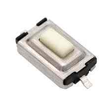
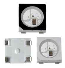
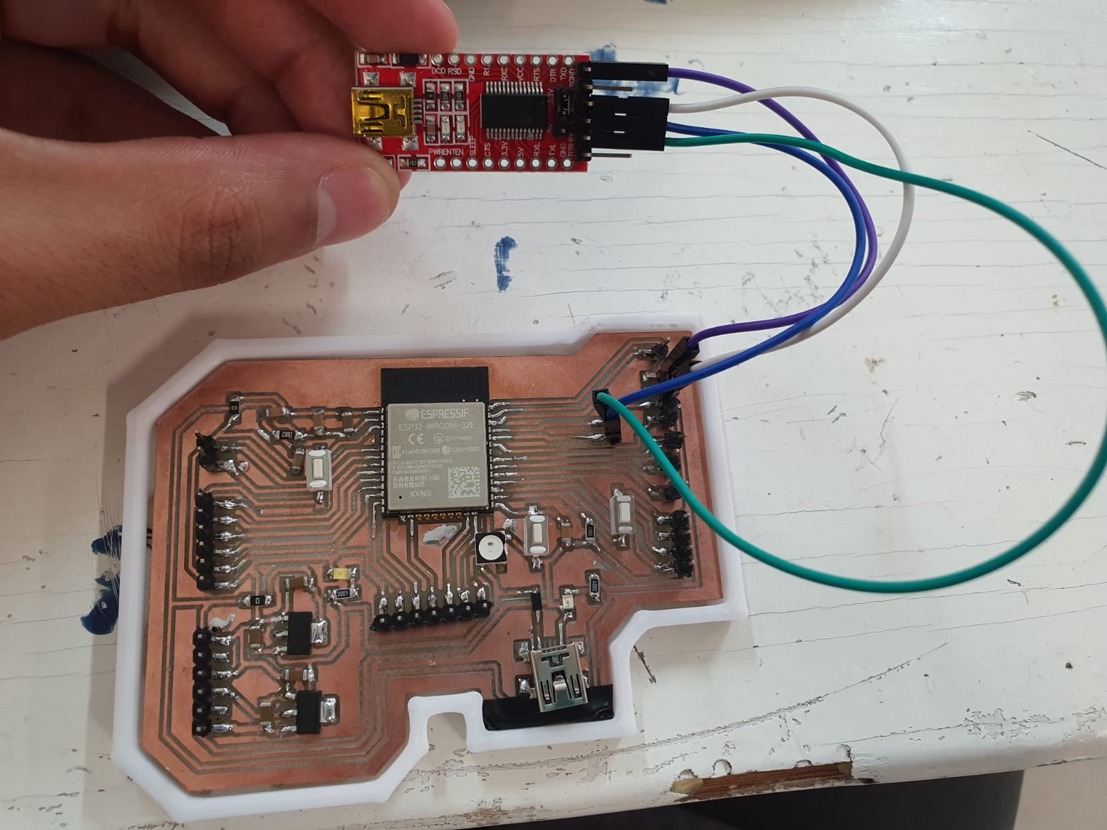
    I added a button (GPIO4) and a Neopixel (GPIO2) for testing that the board works I will be changing its color by pressing the button.
    Steps:

  • With a FTDI conect the esp32 (GND, 3.3V, TX and RX)
  • *Note: verify the FTDI is in 3.3 volts for the esp32
  • Create a code in Arduino
  • When uploading click on the boot button
  • It's done!


  •            


    Code
    
    						#include 
    
    							#define PIXEL_PIN 2
    							#define NUM_PIXELS 1
    							#define BUTTON_PIN 4
    							
    							Adafruit_NeoPixel pixels(NUM_PIXELS, PIXEL_PIN, NEO_GRB + NEO_KHZ800);
    							
    							// Define colors
    							uint32_t colors[] = {pixels.Color(255, 0, 0),   // Red
    												 pixels.Color(0, 255, 0),   // Green
    												 pixels.Color(0, 0, 255)}; // Blue
    							int current_color_index = 0;
    							
    							void setup() {
    							  pixels.begin();
    							  pinMode(BUTTON_PIN, INPUT_PULLUP);
    							}
    							
    							void loop() {
    							  if (digitalRead(BUTTON_PIN) == LOW) { // Button is pressed
    								changeColor();
    								while (digitalRead(BUTTON_PIN) == LOW) { // Wait for button release
    								  delay(10);
    								}
    							  }
    							}
    							
    							void changeColor() {
    							  current_color_index = (current_color_index + 1) % 
    							  (sizeof(colors) / sizeof(colors[0]));
    							  pixels.fill(colors[current_color_index]);
    							  pixels.show();
    							}


    Files