10. Mechanical design, Machine Design
On this week with my group we designed and made a Ceramic 3D printing machine, below I will explain my ocntribution
on this proyect.
Here is the link for the Group Page.
Mechanical design
For the first part we start looking different designs of the machine we can make, how many axis, motors, etc.
After a deep research we found out that some people change the extruder on the ender 3, so we decided to make a
CNC like an Ender with a different extruder mechanism.
The strucure is one of the most important parts beacuse it supports all the weight, stability and vibrations of all the motors and
the extruder. So for first design we opted for aluminum profiles.
At first we make all the structure of 20x20 but at the end we couldn't find the material so we improvise with the dimensions.
ITEM
For previous projects I have used ITEM designing tool, So I figured out that it would be a good idea to use it for the first design.
For the procurement of key components in the construction of our CNC machine for ceramic printing, we turned to the company Interface
by ITEM. Specialized in the design and manufacturing of a wide range of aluminum profiles and other metals, this company represented
a promising option to obtain the materials needed for the structure of our project. With the expectation of acquiring the right
aluminum profiles for our machine, we trusted in the quality and variety of products offered by Interface by Item to meet our
design and construction needs.
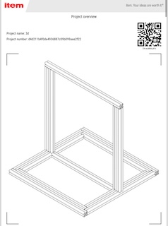
A team mate continue with all the design in Solidworks
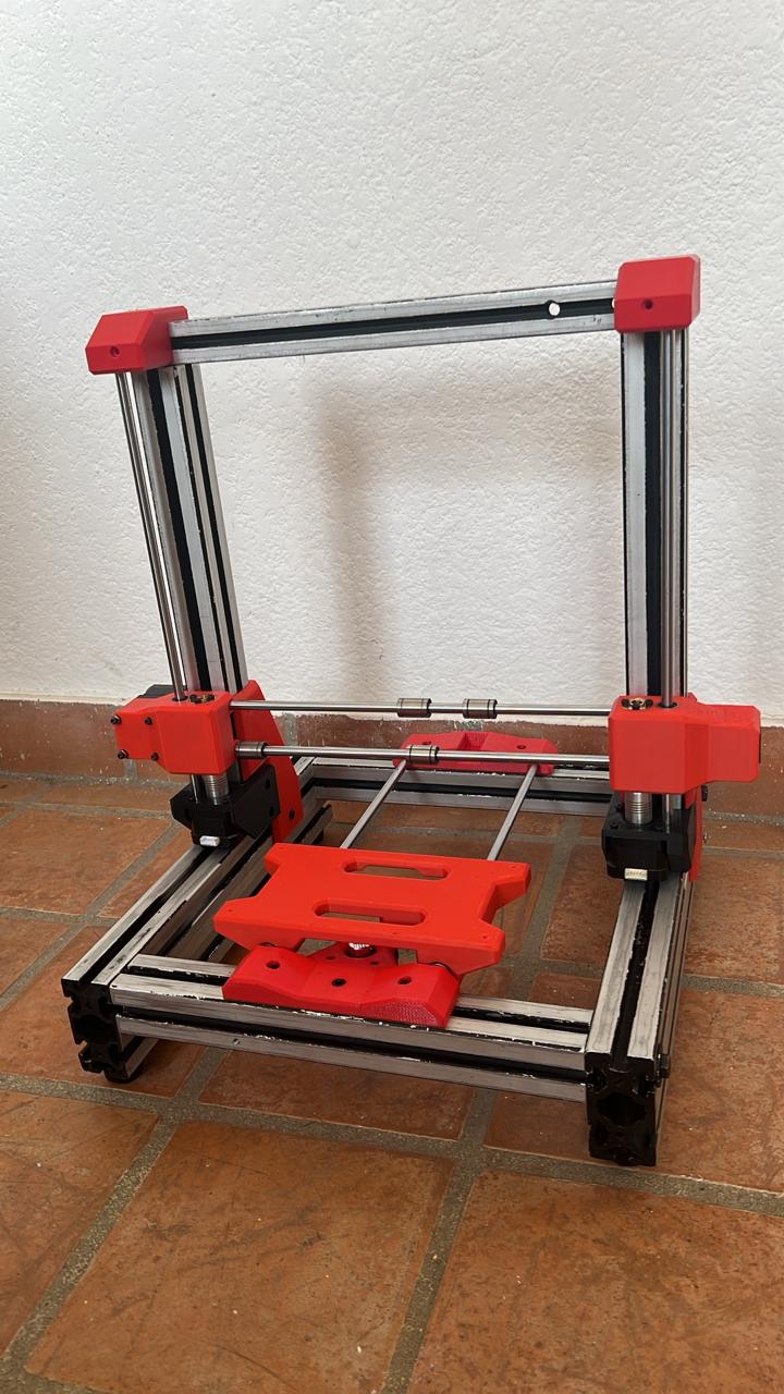
After having all the parts we needed and a render of how it will looked we can start to assembly the machine.
| Material | Size/Quantity |
|---|---|
| Aluminum profile 40x80 mm | |
| Aluminum profile 40x40 mm | |
| Aluminum profile 30x30 mm | |
| Screw M8 | 6 |
| Screw M6 | 26 |
| Screw M3 | 25 |
| Washer | 16 |
| 3mm colored acrylic | 1200 cm2 |
| 6mm transparent acrylic | |
| Screw rods | 57 |
| Sliders | 6 |
| Linear bearings | 6 |
| Guide shafts | |
| Nema 17 motors | 5 pieces |
| MDF | |
| 12V switched-mode power supply | 1 |
| Arduino Mega | 1 |
| CNC shield for Arduino | |
| PLA filament | 1 kg |
| Nema 25 motor | 1 piece |
| DM860 driver | 1 piece |
| DRV8825 driver | 1 piece |
| Rubber feet | 8 pieces |
| 2-inch acrylic tube | 33 cm |
| TPU filament | |
| 1/2 inch PVC hose | |
| 14 gauge wire | |
| Cable organizer | 5 meters |
| Ribbon cable | |
| Nema 15 socket with fuse | |
| Illuminated switch | |
| Red acrylic decorations | 8 pieces |
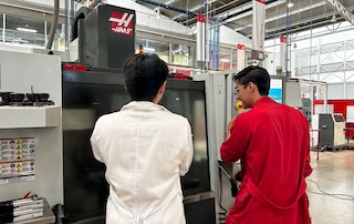
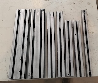
First cutting the profiles and then calibrate them, with the specific measurements in the Haas machine, which allowed for the highest precision possible for the assemblies.
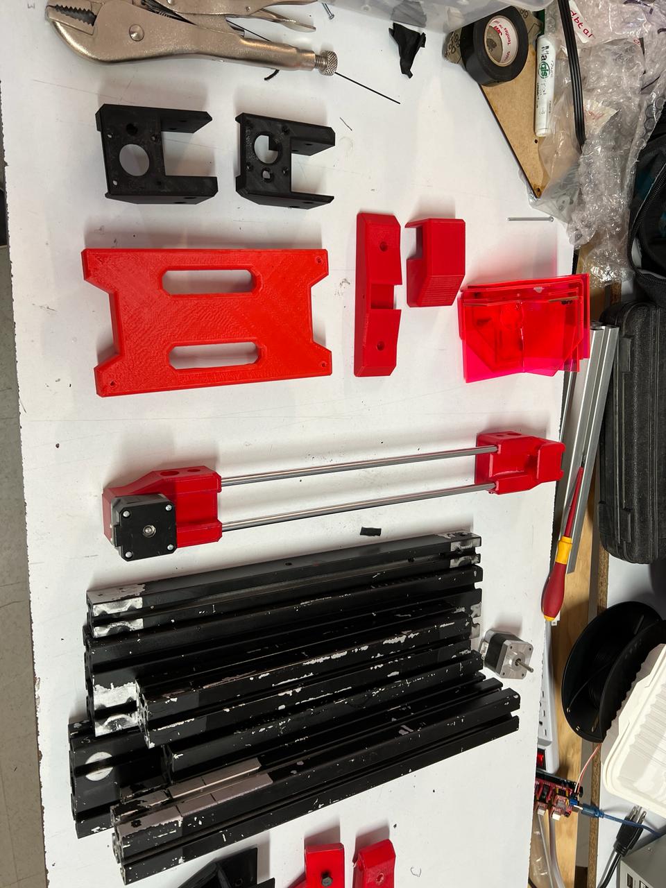
Assemble the pieces with their respective screws to each profile.
Step 3
Assemble the motors in place and adjust them using the previously printed pieces.
Step 4
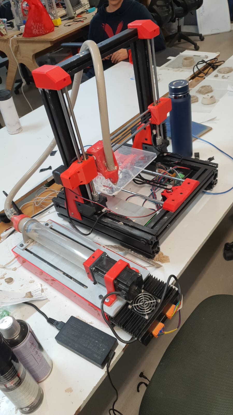
Place the switched-mode power supply at the bottom and assemble it for further adjustment.
Step 5
Assemply all the parts first, for the Bed and carrusel.
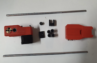
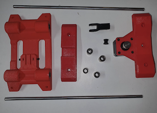
Step 6
With the structure assembled and the switched-mode power supply in place, which connects to our motherboard, we were ready to program.
Machine Design
After having all the machine alligned and all the moving parts move smooothly it its time to connect the motors. We will use Marlin
to control the machine and the End stops.
We change some important parameters such as:
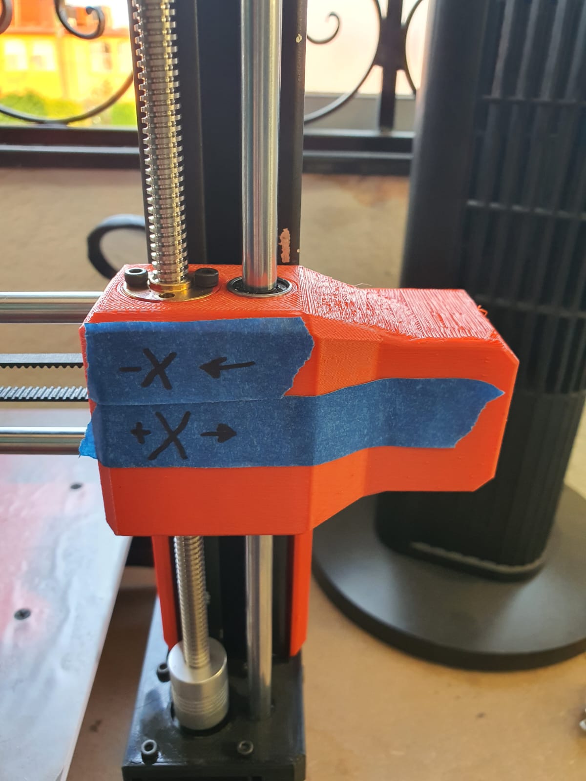
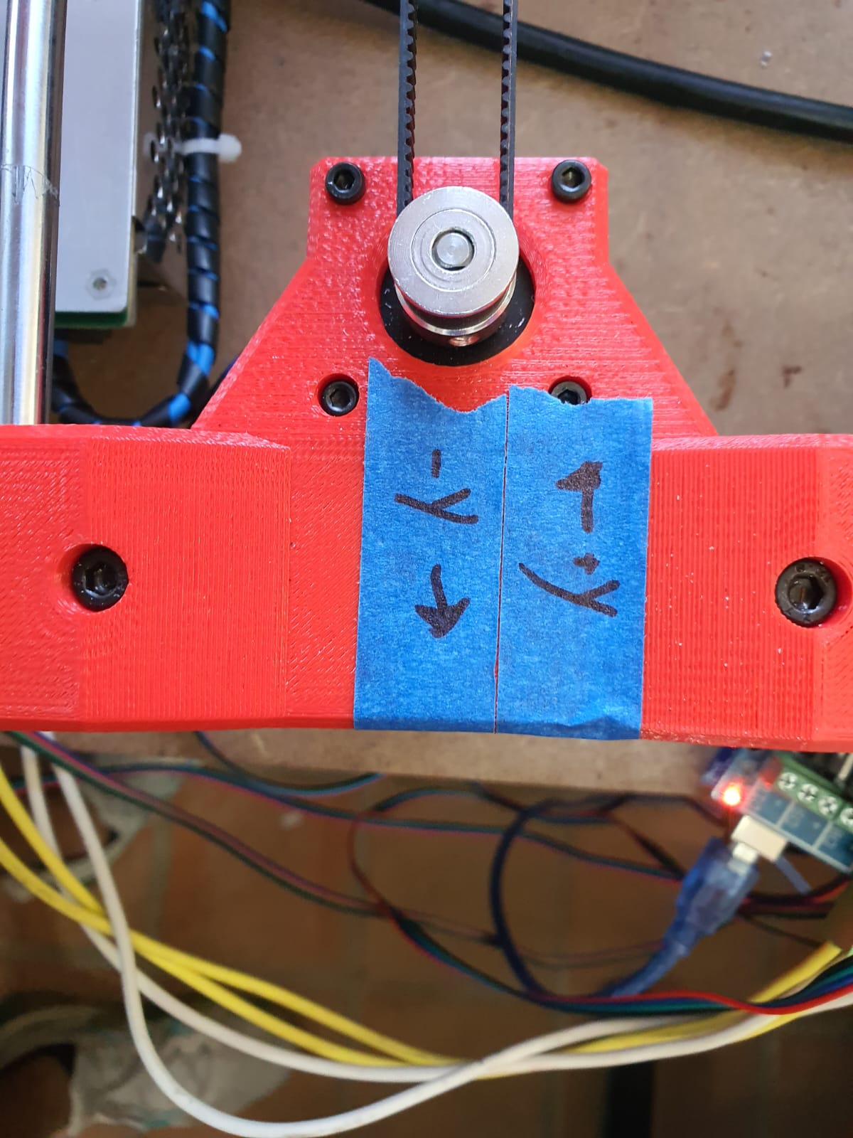
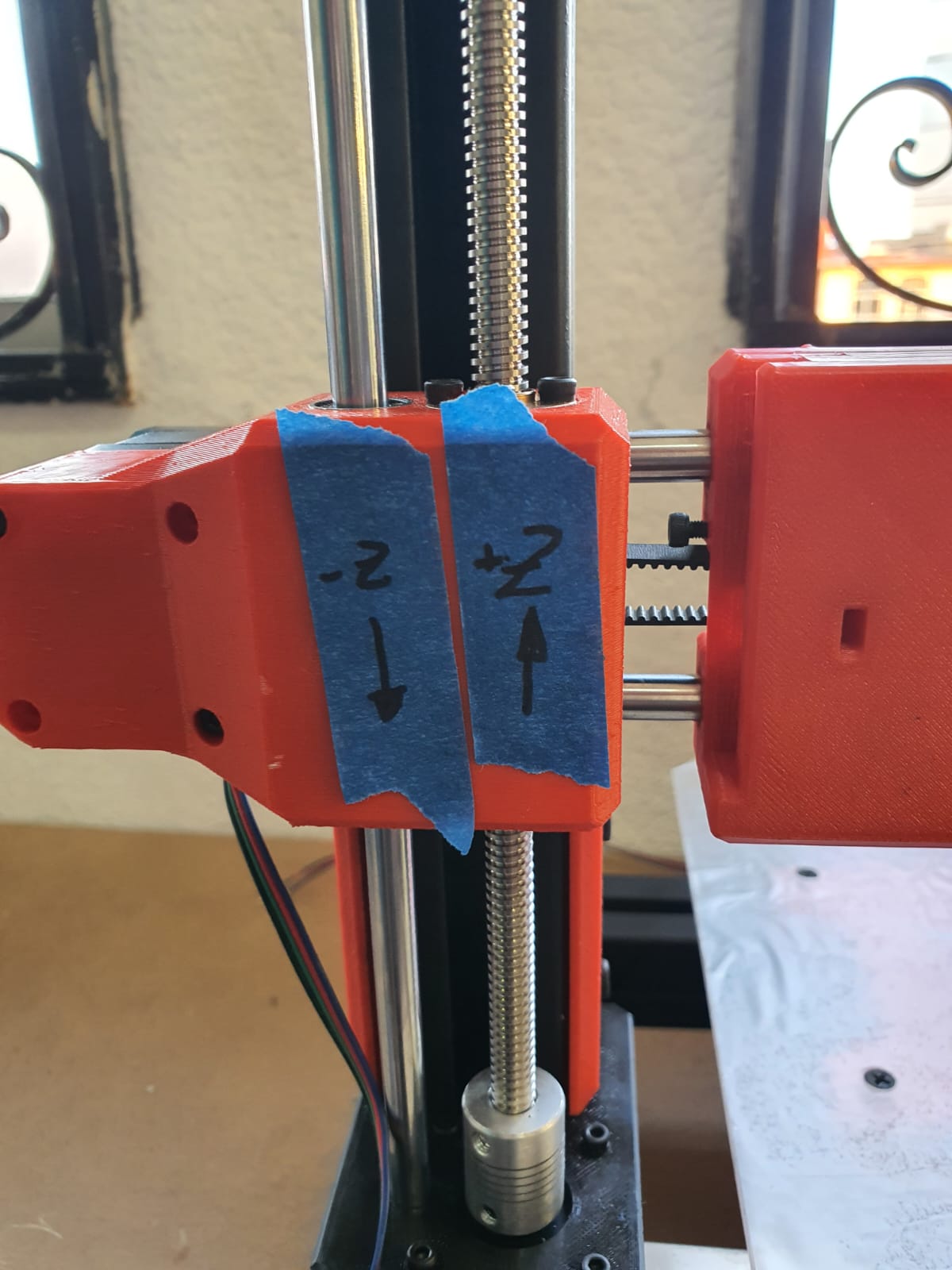
For the steps we first send to move 100mm and move the real distance, so afterward we only make a rule of three.
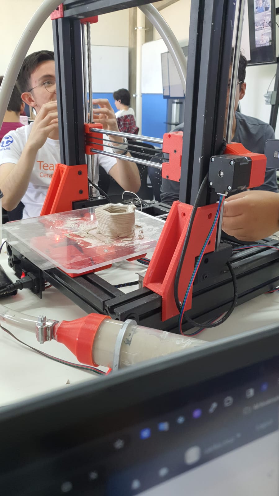
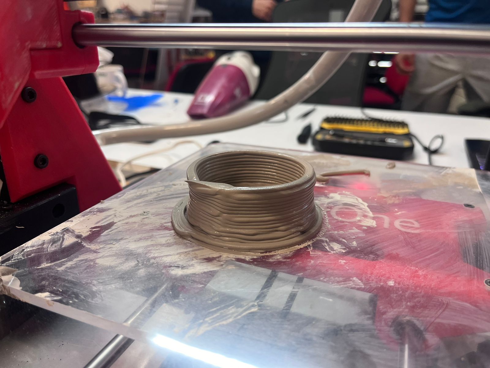
Results
Files