WEEK10
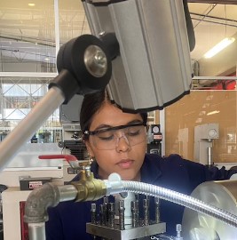
TEAM 1 "CERAMIC PRINTER"
- Design a machine that includes mechanism + actuation + automation + application
- Build the mechanical parts and operate it manually
Ceramic printer CNC
Student Assignments Links


If you want to download or see more details about each component, please visit our group pages where you will find more information.
FINAL VIDEO RESULT
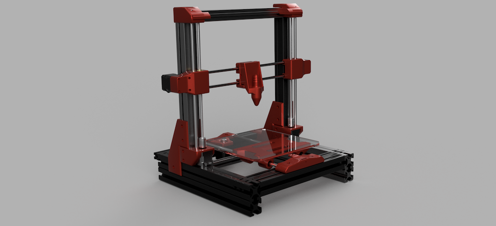
CeraPrintV1
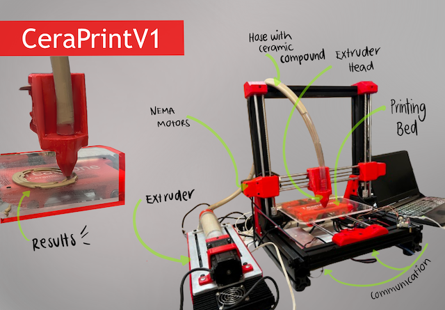
- CNC idea description -
The CNC machine project for ceramic printing is born out of a specific necessity: to enhance and expedite the manufacturing process of ceramic items. Recognizing the constraints and hurdles confronted by artisans and manufacturers in this domain, our goal was to devise a technological solution that melds the precision of a CNC machine with the versatility and resilience of ceramics. This endeavor arises in answer to the call for an efficient and approachable tool, enabling a broad spectrum of users to explore and bring their ideas to fruition in the realm of ceramics.
-Materials list -
| Material | Size/Quantity | |
|---|---|---|
| Aluminum profile 40x80 mm | ||
| Aluminum profile 40x40 mm | ||
| Aluminum profile 30x30 mm | ||
| Screw M8 | 6 | |
| Screw M6 | 26 | |
| Screw M3 | 25 | |
| Washer | 16 | 3mm colored acrylic | 1200 cm2 | 6mm transparent acrylic | Screw rods | 57 | Sliders | 6 | Linear bearings | 6 | Guide shafts | Nema 17 motors | 5 pieces | MDF | 12V switched-mode power supply | 1 | Arduino Mega | 1 | CNC shield for Arduino | PLA filament | 1 kg | Nema 25 motor | 1 piece | DM860 driver | 1 piece | DRV8825 driver | 1 piece | Rubber feet | 8 pieces | 2-inch acrylic tube | 33 cm | TPU filament | 1/2 inch PVC hose | 14 gauge wire | Cable organizer | 5 meters | Ribbon cable | Nema 15 socket with fuse | Illuminated switch | Red acrylic decorations | 8 pieces |
Design Process
During the design phase of our CNC machine for ceramic printing, we utilized tools such as the item interface and SolidWorks. These programs enabled us to create accurate and detailed models of each component, streamlining the visualization and optimization process prior to physical manufacturing.
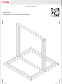
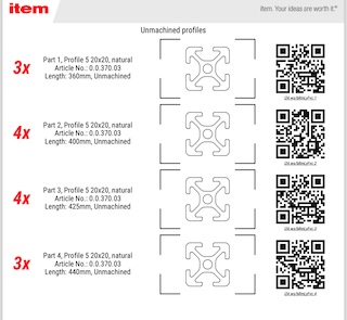
-Designing the structure using the ITEM interface.-
For the procurement of key components in the construction of our CNC machine for ceramic printing, we turned to the company Interface by ITEM. Specialized in the design and manufacturing of a wide range of aluminum profiles and other metals, this company represented a promising option to obtain the materials needed for the structure of our project. With the expectation of acquiring the right aluminum profiles for our machine, we trusted in the quality and variety of products offered by Interface by Item to meet our design and construction needs.
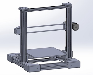
-Designing the structure using SolidWorks-
During the design stage of our CNC machine for ceramic printing, the key tool employed was SolidWorks. In this software, we not only input real measurements of the structure but also accounted for necessary adjustments due to the limited availability of expected aluminum profiles. By incorporating profiles of three different dimensions, our approach was meticulous in placing the motors and planning the connections of the pieces to ensure smooth assembly and a sturdy structure. SolidWorks provided us with the capability to visualize and refine every detail, allowing us to adapt efficiently to changes in the design and ensuring a solid foundation for the physical construction of the machine.

-Designing the ceramic extruder-
For the design of the ceramic extruder, the main idea was to create a ceramic container resembling a tortilla machine. At the top, there would be a hopper where the mixture would be inserted. A screw of the length of the container, connected to one of the motors, would rotate to extrude the material. This was test 1.
-Test 1-
As observed, the internal screw was not extruding the material; instead, it was only pushing it back. Despite constantly adjusting the motor power, it continued to malfunction.
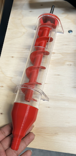
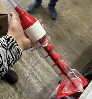
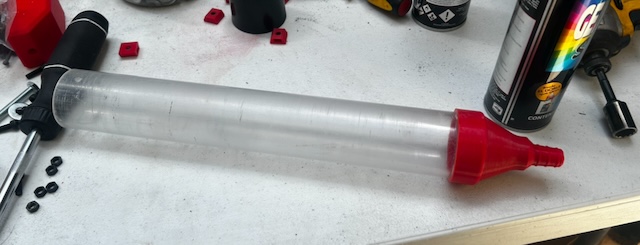
-Test 2-
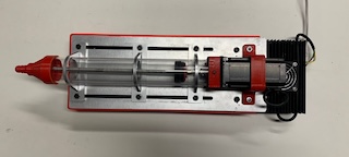
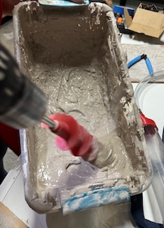
For test number two , the same ceramic container design was made without the hopper. Now, it includes a screw and a spindle that advances as the motor rotates, allowing the material to be extruded into the hose, which will be connected to the second part of the extruder, where the motor operation will be programmed.
As you can see, the second test was successful. We used a drill to simulate the motor, and the piston worked."
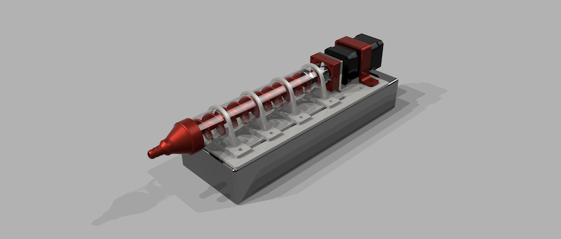
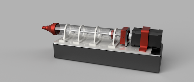
- Extruder Assembly-
With the extruder concept ready, a 3D modeling simulation was performed to check assemblies.
At the same time we desing our 3D print pieces for the extruder.
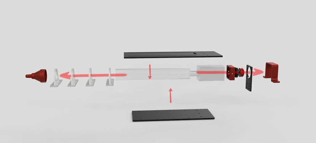
STEP 1
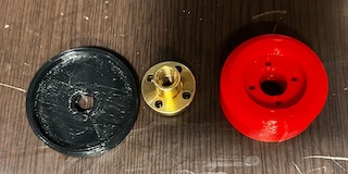
A 2-inch acrylic tube was cut to a length of 32 cm, and similarly, the spindle had to have that length and a diameter of 8mm, which would connect to our Nema motor.
STEP 2
In between these, there would be 2 supports with drilled holes to be fastened with screws. Likewise, the spindle design contains our 3D piece to fit the internal diameter of the acrylic tube.

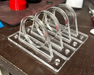
STEP 3
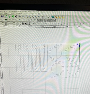
Support pieces for the acrylic tube were designed and laser cut from 6mm acrylic. There were 8 pieces assembled together.
STEP 4
The piston part was designed in SolidWorks, as well as the supports for the base that holds the motor and the ceramic container.
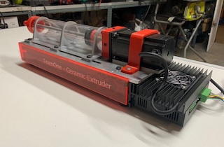
STEP 5
Everything is assembled, and the motor is connected to its own driver for programming.
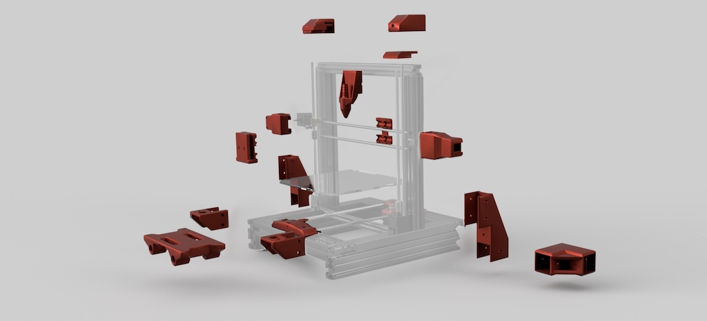
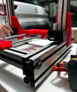
-Structure Assembly-
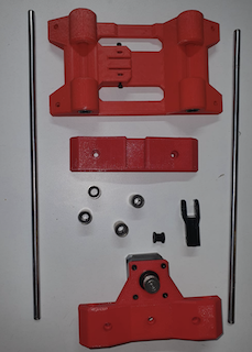
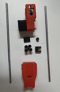
At this point, all the specific pieces for the structure were ready, along with the 3D prints that would hold it together.
At the same time we desing our 3D print pieces for the structure.
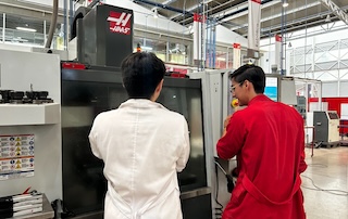
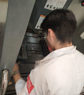
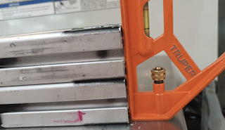
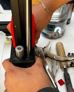
STEP 1
First cutting the profiles and then calibrate them, with the specific measurements in the Haas machine, which allowed for the highest precision possible for the assemblies.

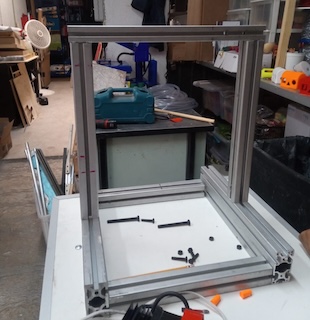
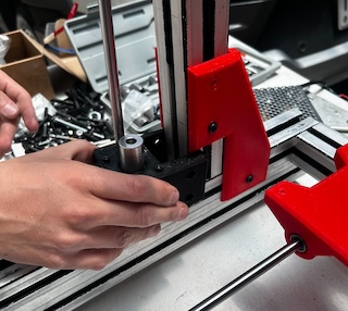
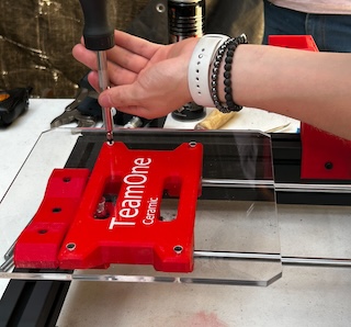
STEP 2
Assemble the pieces with their respective screws to each profile.
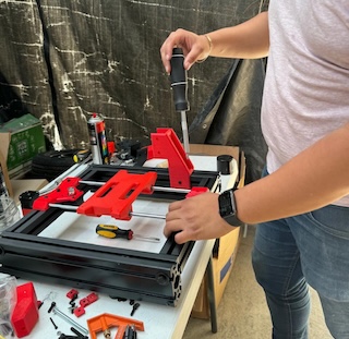
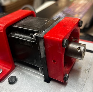
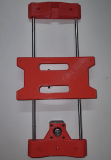
STEP 3
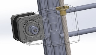
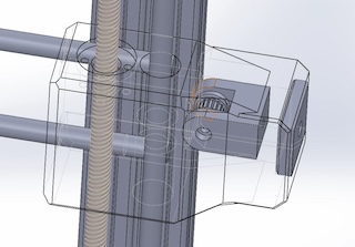
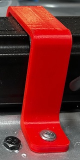
Assemble the motors in place and adjust them using the previously printed pieces.
STEP 4
Place the switched-mode power supply at the bottom and assemble it for further adjustment.
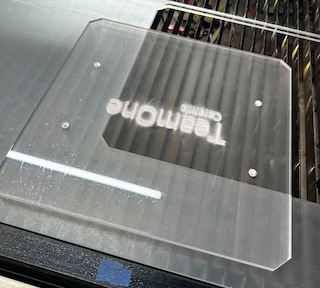
STEP 5
Laser cut a 6mm acrylic bed to fit onto the screw of our CNC

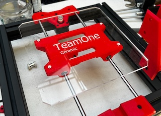
STEP 6
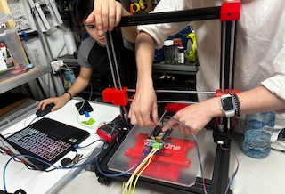
With the structure assembled and the switched-mode power supply in place, which connects to our motherboard, we were ready to program.

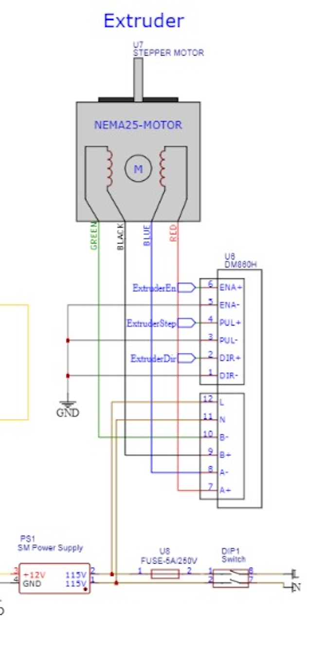
-Extruder wiring-
For the wiring from the power supply to the extruder motor, the diagram was as follows:
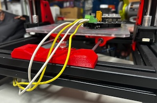
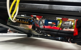
-Structure wiring-
In this case, the wiring went from our switched-mode power supply to our motherboard and to our NEMA motors.
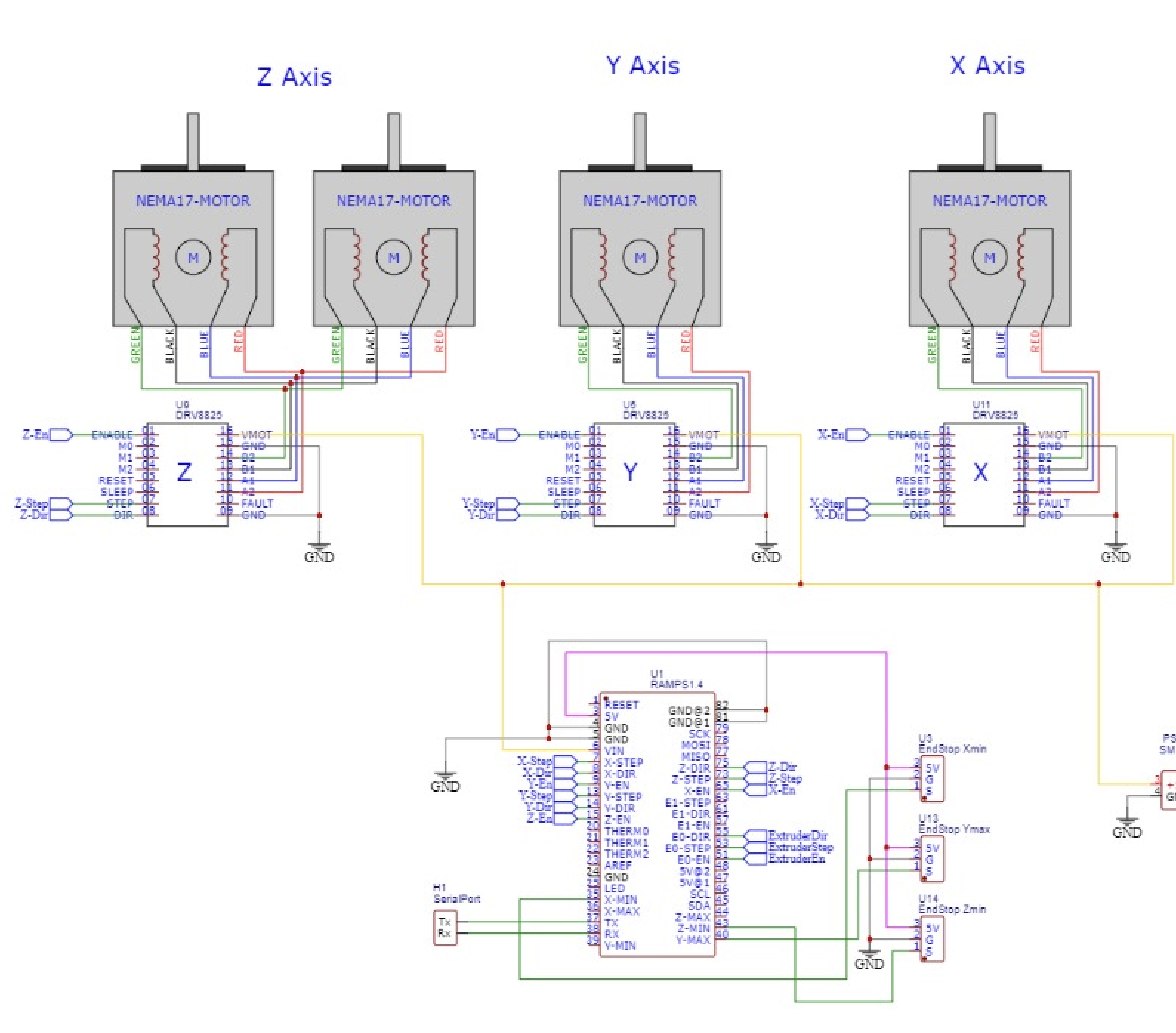
Complete wiring
This one is the whole wiring of our CNC ceramic printer.

-CERAMIC EXTRUDER PROGRAMMING
For the extrusion test of our CNC, we used a program, in this case, it was MARLIN. Likewise, we sent all that communication to our motherboard to calibrate our machine and be able to start printing.
Marlin Firmware
Marlin is an optimized firmware for RepRap 3D printers based on the Arduino platform. It is highly customizable and supports various 3D printer configurations and hardware setups, including ARM and AVR-based boards.
Download Links
Additional Resources
If you want to download or see more details about Marlin firmware, please visit the links provided above.
STEP 1
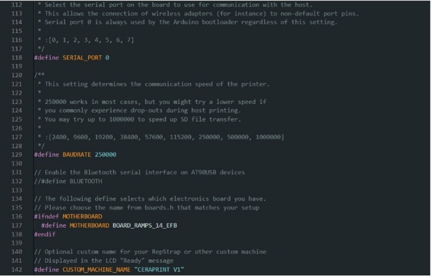
These are the parameters that we modified for the machine configuration. We used the Marlin program.
Motherboard refers to the board we are using.
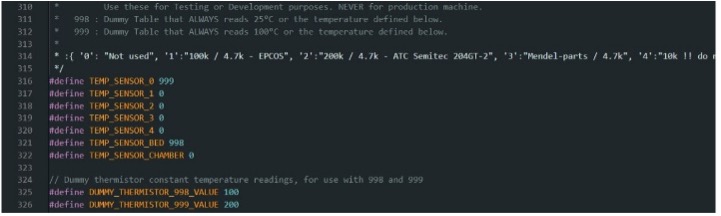
STEP 2
Since our machine does not utilize temperature sensors, we employed fictitious sensors included in Marlin to prevent program malfunctions.
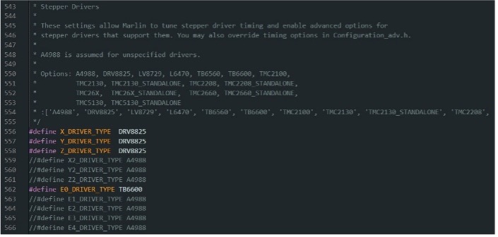
STEP 3
We assigned the drivers that we are using on the board.
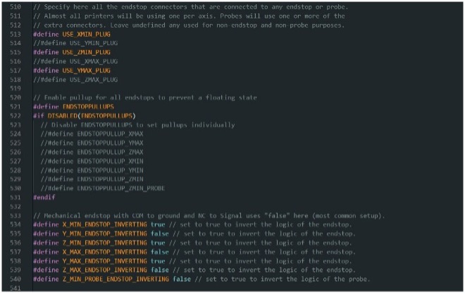
STEP 4
This is the configuration of the limit switches that we are using for our specific machine.
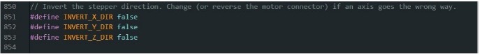
STEP 5
We set the direction of the motors.
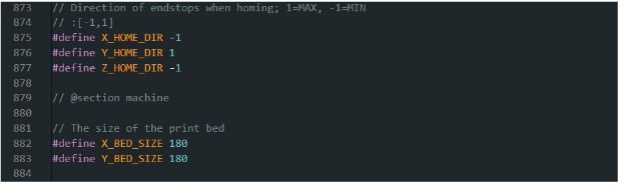
STEP 6
We establish the home direction of the axes and the size of the printing bed.
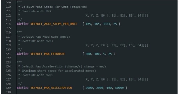
STEP 7
We set the steps per mm of the motors and their accelerations.
-CERAMIC PASTE
With the programming and communication set up, and the machine calibrated, we proceeded to carry out our test prints of a basic piece.
STEP 1
To make our ceramic paste, we need a ceramic called "line ceramic," specially designed for industrial processes, as its chemical components allow us to extrude in the best possible way.
STEP 2
To make the mixture that fills our extruder and hose, we need 340 grams of ceramic powder per 120 milliliters of water.
-CERAMIC EXTRUDER TEST
With the programming and communication set up, and the machine calibrated, we proceeded to carry out our test prints of a basic piece.
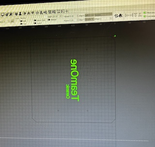
STEP 1
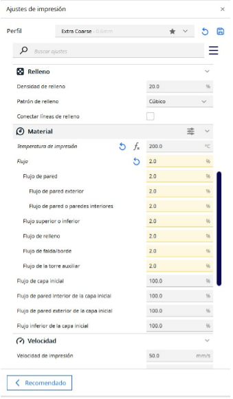
Ultimaker Cura is the program used for slicing the ceramic pieces. By modifying the parameters available in the program, we can take it to our machine.
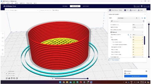
STEP 2
These are the printing parameters.


STEP 2
This is the Pronterface program with which we control the machine and can load G-code only during tests.
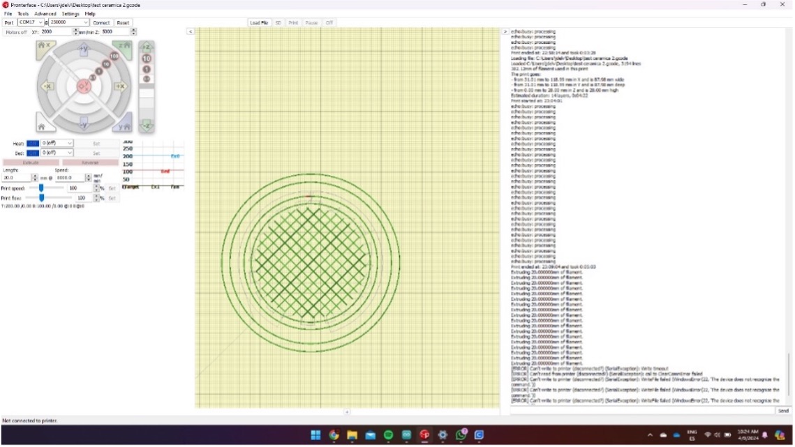
TEST 1
This is our test number one, we send it a basic piece. Basically just circles.
As we can see, the issue in this test was the air trapped inside the hose, which prevented continuous extrusion. Additionally, we noticed that we needed to increase the motor speed slightly to achieve smoother extrusion. Furthermore, the wall flow was set at 2%, and we increased it to 5% for the next test.
TEST 2
We conducted the second test, and here we made the print model taller to see how well it holds up with the material mixture.
As we can see,this test was succesful.
-INTERFACE FOR OUR CERAMIC PRINTER
To manage our ceramic printer, we decided to create an interface, the purpose of which is to send the G-code from Ultimaker Cura of our pieces to our ESP32, which connects to our motherboard and sends all the information to carry out the task.

-INTERFACE PROCESS
On the client side, various services were utilized to enhance the user experience. Pako was used to compress the file uploaded by the user from the client side, and then it could be decompressed on the server side using ESP32-targz. The maximum file size that can be used for printing is 1MB due to the memory limitations of ESP32. The SD.h library is used to operate with a microSD memory for persistence. This same memory stores the HTML page that is sent to the client, this is due to the weight of the HTML as a string.
On the server side, functions such as handleRoot, targzPrintLoggerCallback, handleFileDelete, handleFileUpload, handleFileList, and handlePrint were implemented.
handleRoot was used to read index.html from the microSD memory and send the interface to the client side.
targzPrintLoggerCallback was used to decompress the files sent by the client on the server side.
handleFileDelete was used to allow the user to delete G-code files from the microSD memory from the client side.
handleFileList was used to list the files available on the microSD ready for printing.
handlePrint is the function used to read the file selected by the user and send line by line the code from the ESP32 to the RAMPS 1.4.