Mechanical design
Linked to the group assigment page
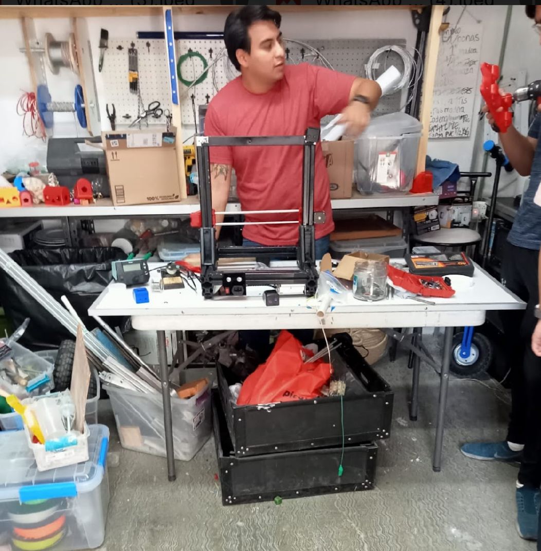
This week was challenging yet fascinating. As a team, we managed to build a ceramic 3D printer, a project that, despite the challenges, was successfully completed. Although we worked together throughout the entire machine development process, I would like to highlight my personal contributions.
research
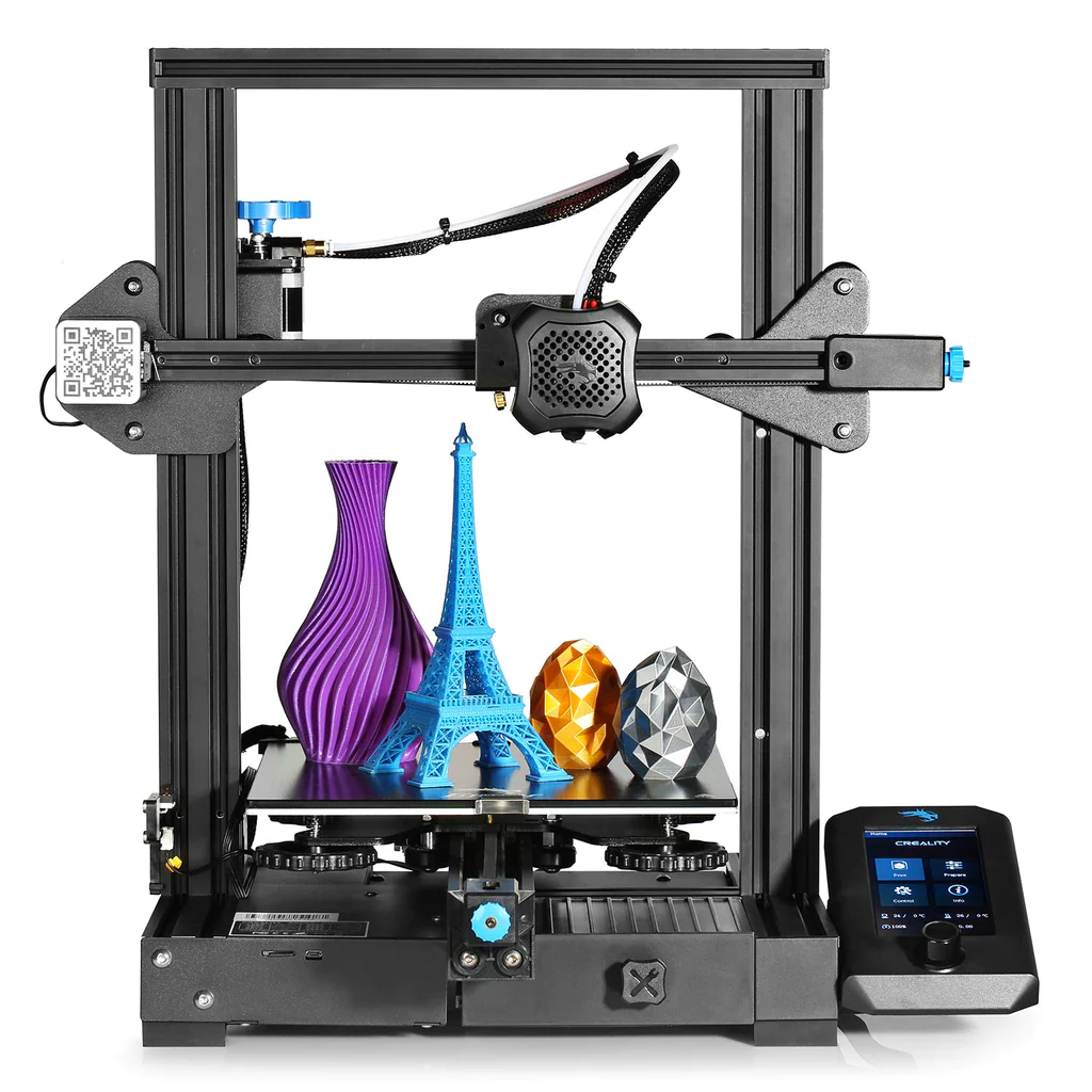
In the development of our project to build a ceramic 3D printer, it was essential to conduct thorough research to understand all the critical factors involved in this innovative process. The decision to adopt the design of an Ender 3 as a reference was based on its proven efficiency and adaptability in the field of 3D printing. This decision allowed us to focus on the necessary modifications to handle ceramic materials, which present specific challenges in terms of temperature, structural support, and extrusion precision. The research covered key aspects such as the selection of suitable materials for the printer parts, the optimal temperature settings for the sintering of ceramics, and the appropriate digital modeling techniques to ensure successful outcomes.
Once we have the design in mind, we prefer to focus on thinking about the extrusion of the material since it is a complicated material to manipulate.
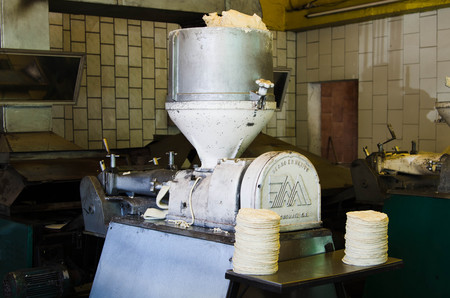
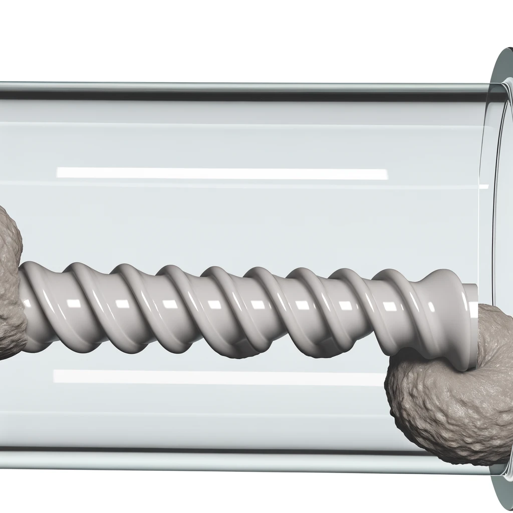
Personally, he works on the design of the extruder and we started thinking of it as a tortilla machine when it makes the dough, but in this case we would pass the ceramic with an Archimedean screw.
prototype ideas
design
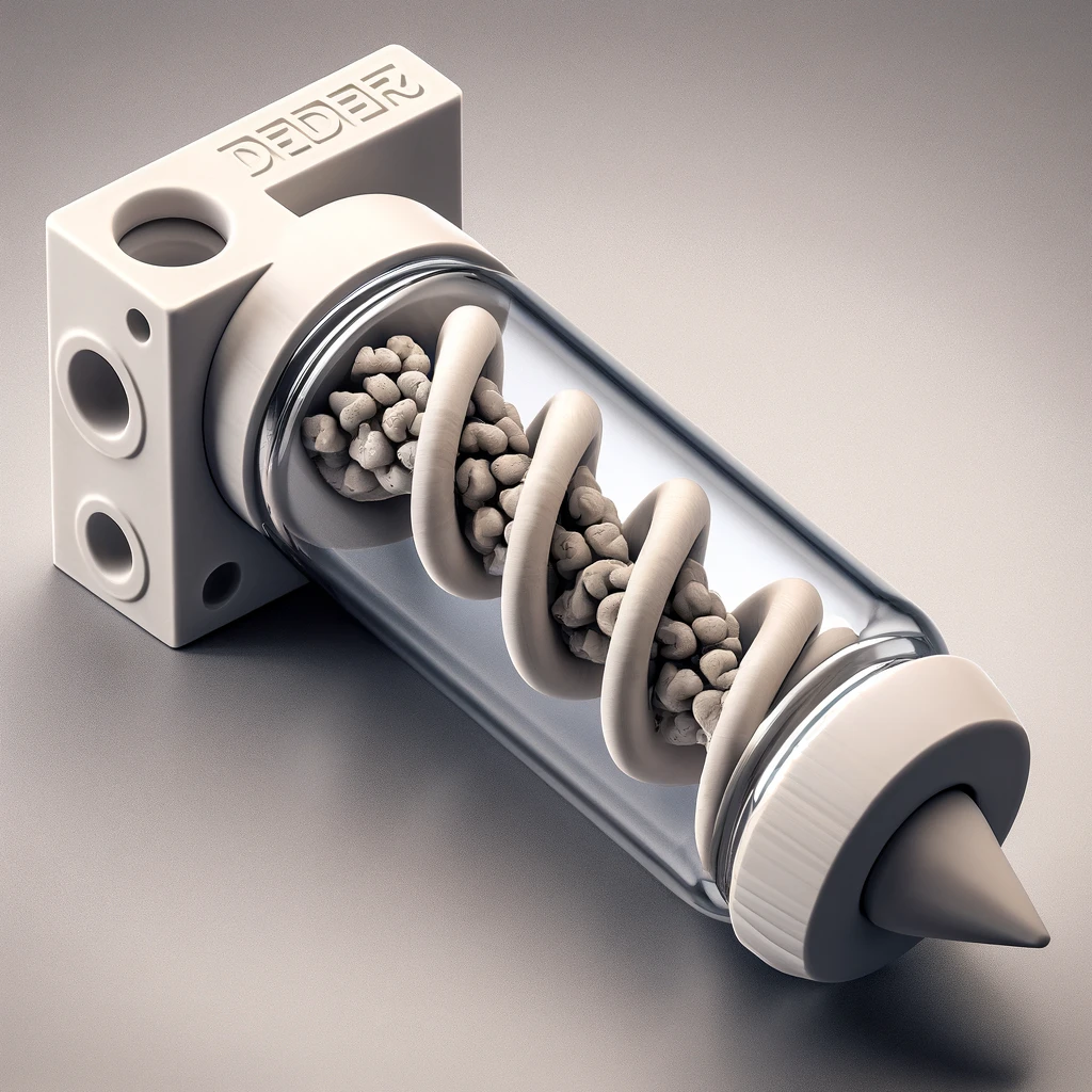
Steps to Create an Archimedes Screw in SolidWorks
Step 1: Create the Thread Profile
- Open a new sketch on an appropriate plane (e.g., the top plane).
- Draw a circle with the desired outer diameter of the screw (e.g., 15.6 mm) and center it at the origin.
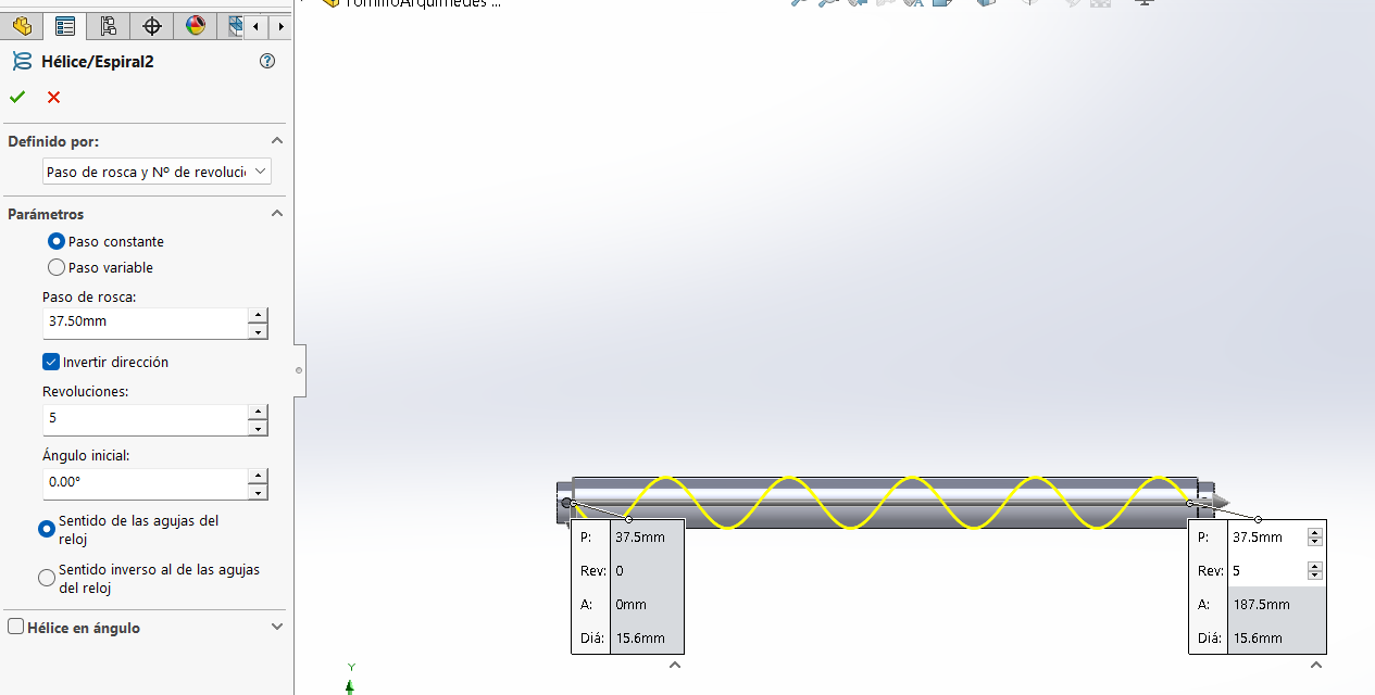
Step 2: Create the Helix
- Select the helix/spiral tool in the features menu.
- Configure the helix parameters:
- Thread pitch: 37.50 mm
- Number of revolutions: 5
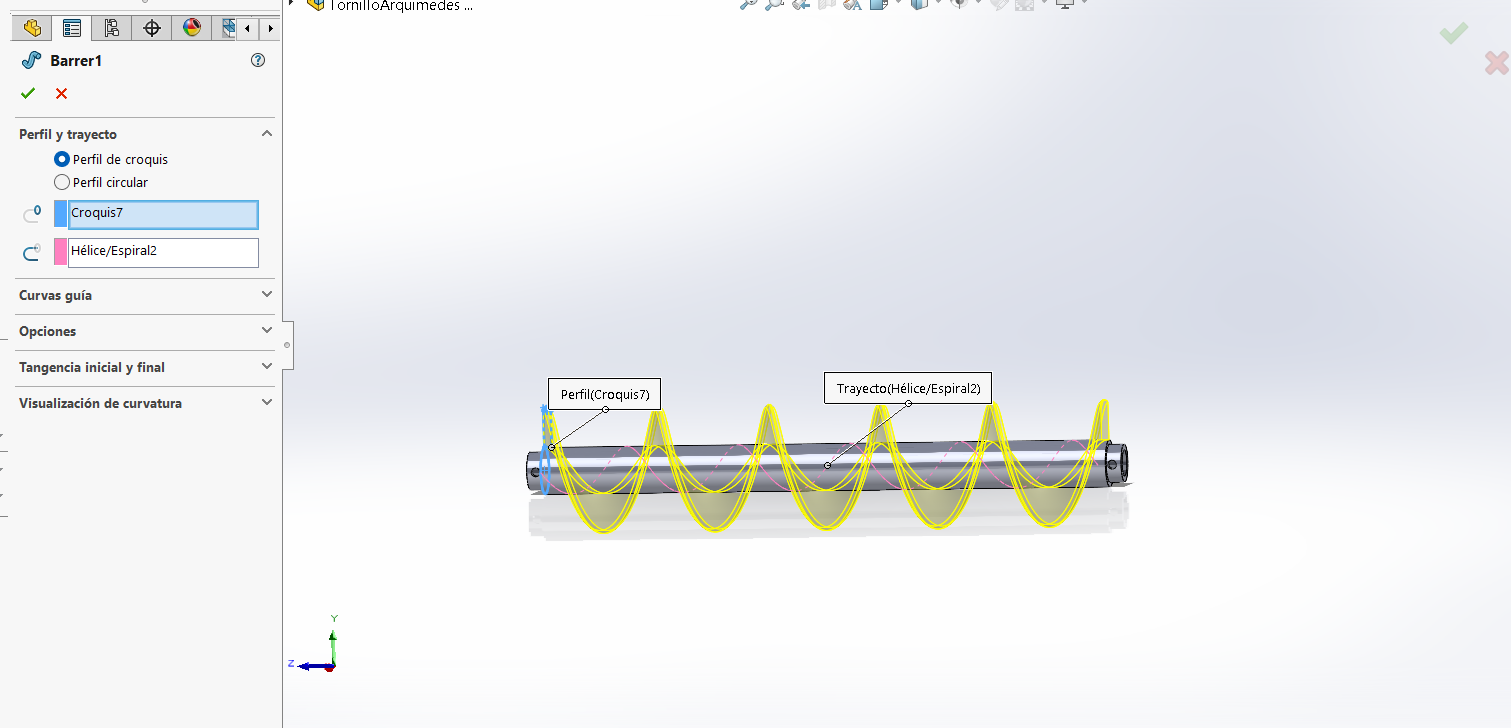
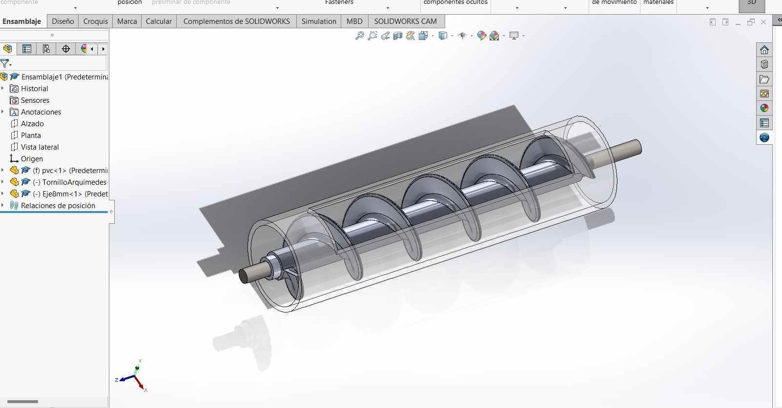
Step 3: Create the Helix Profile
- Draw the helix profile in a new sketch, ensuring it aligns with the helix path created in the previous step.
- Use the sweep tool to sweep the profile along the helix path.
Step 4: Adjust the Helix
- Round the edges of the screw with a 3 mm radius. This enhances the screw's strength and stability, preventing breakage during rotation.
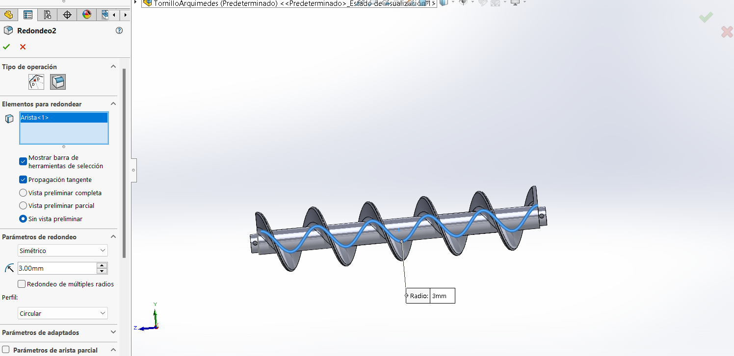
The rounding applied to the screw edges (with a 3 mm radius) improves the screw's firmness and stability, reducing stress points and wear during rotation, preventing fractures, and ensuring the screw's durability.
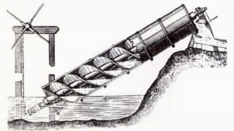
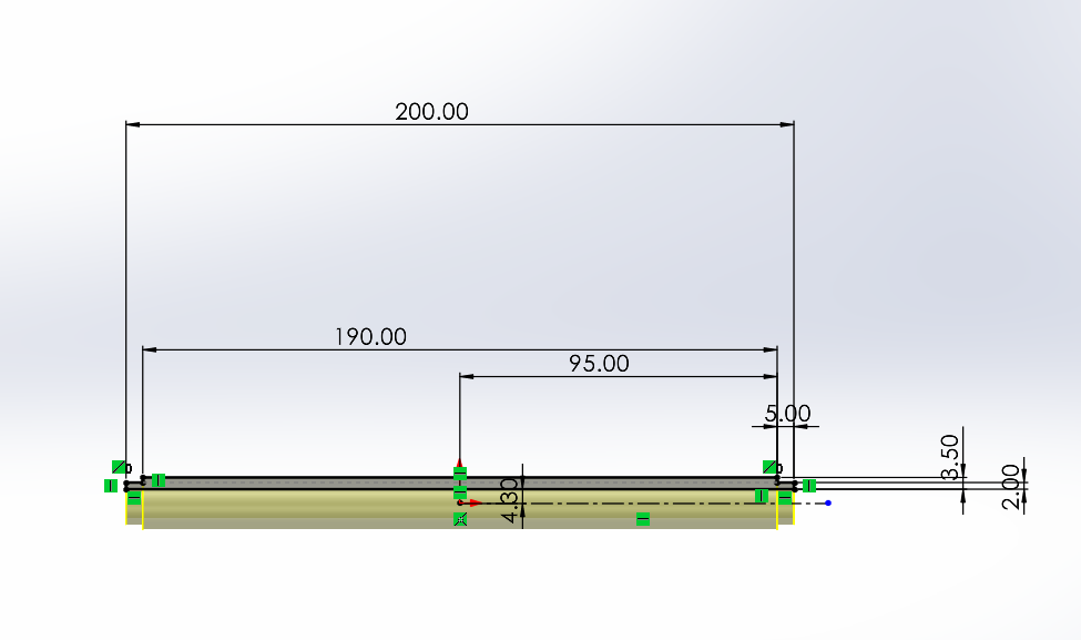
Justification of Thread Pitch and Revolutions
The initial choice of a 37.50 mm pitch and 5 revolutions was based on the formula:
L = P x N
Where:
- L is the total length of the screw (200 mm in this case).
- P is the thread pitch (37.50 mm).
- N is the number of revolutions (5).
200 mm = 37.50 mm x 5
Advantages of this Configuration
- Flow Optimization: A larger thread pitch facilitates material movement through the screw, allowing for faster and more efficient transport, crucial for viscous materials like ceramics.
- Transport Efficiency: The combination of a 37.50 mm pitch and 5 revolutions provides a balance between speed and control in material transport, preventing clogs and ensuring constant extrusion.
- Cost and Time Reduction: This methodology allows for rapid estimation and optimization of the screw design, reducing initial research and development costs.
Problems Encountered
During initial tests, it was observed that the configuration with a 37.50 mm pitch allowed ceramic material to escape between the screw threads, resulting in inefficient extrusion.
Proposed Solution
A new configuration with an 8 mm pitch and 24 revolutions was proposed:
L = 8 mm x 24 = 192 mm
This configuration significantly reduces the space between the screw threads, minimizing material escape and ensuring more controlled and constant flow. The increased number of revolutions improves material confinement within the screw, optimizing the extrusion process.
Experiment Limitations
Due to time and resource constraints, this new configuration could not be experimentally tested. As a practical and quick solution, a 3D printer screw with a 2 mm pitch was used to ensure the prototype's functionality within the available time.
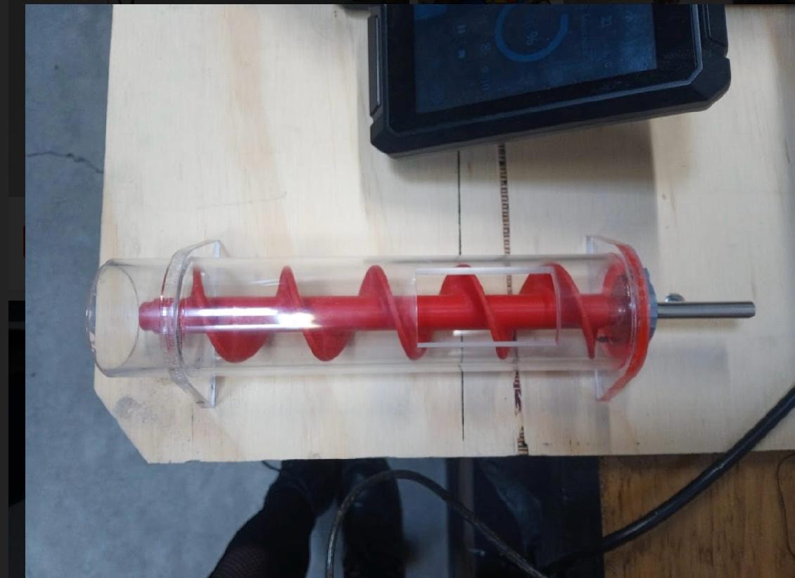
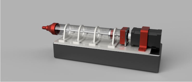
final prototype
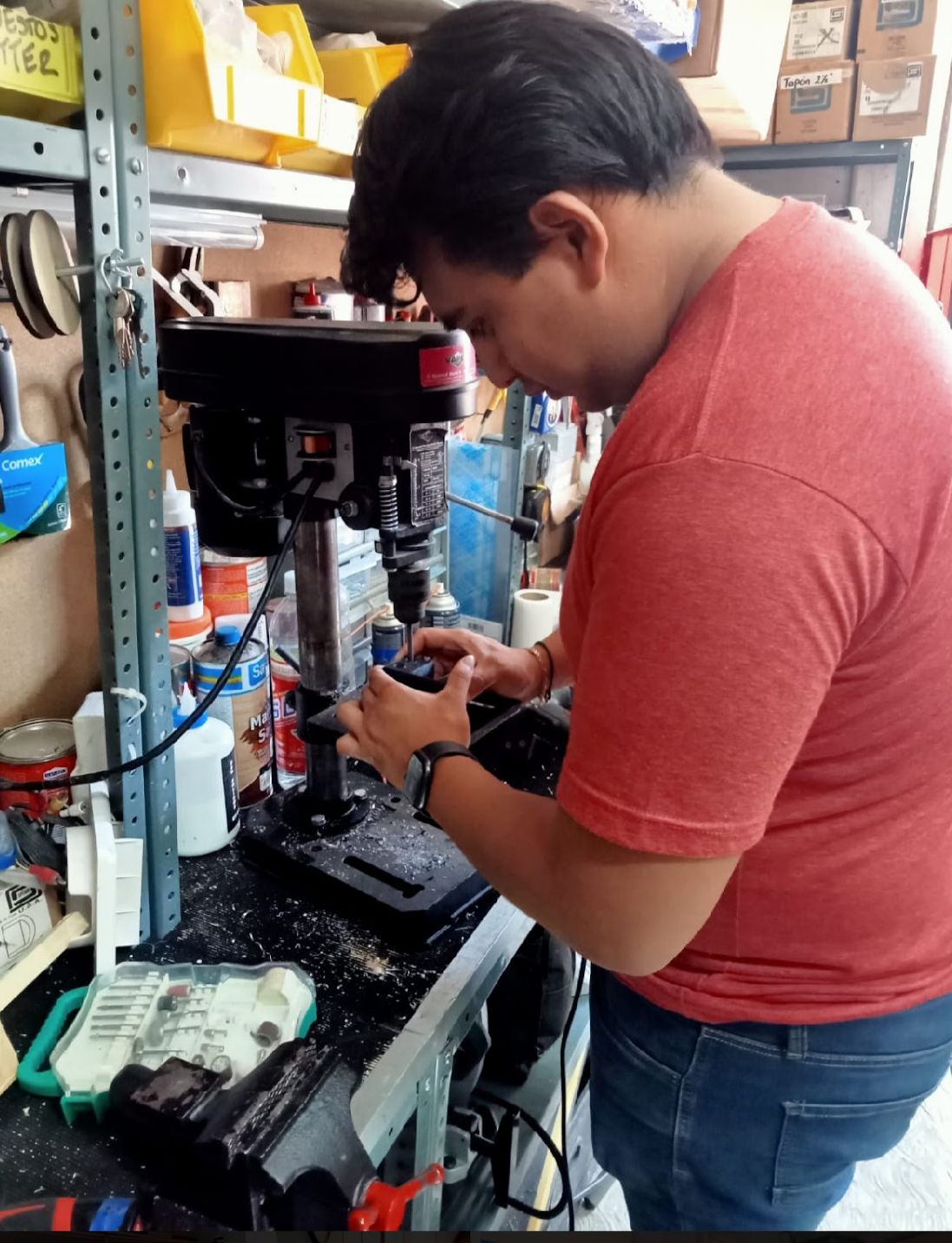
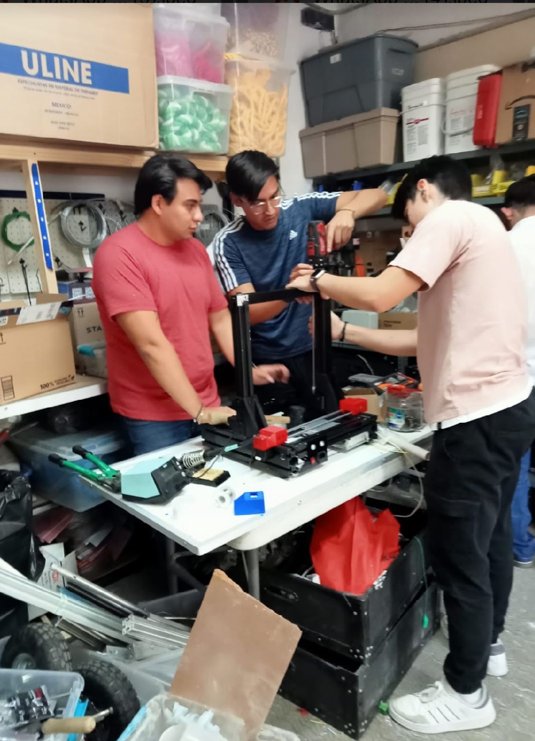
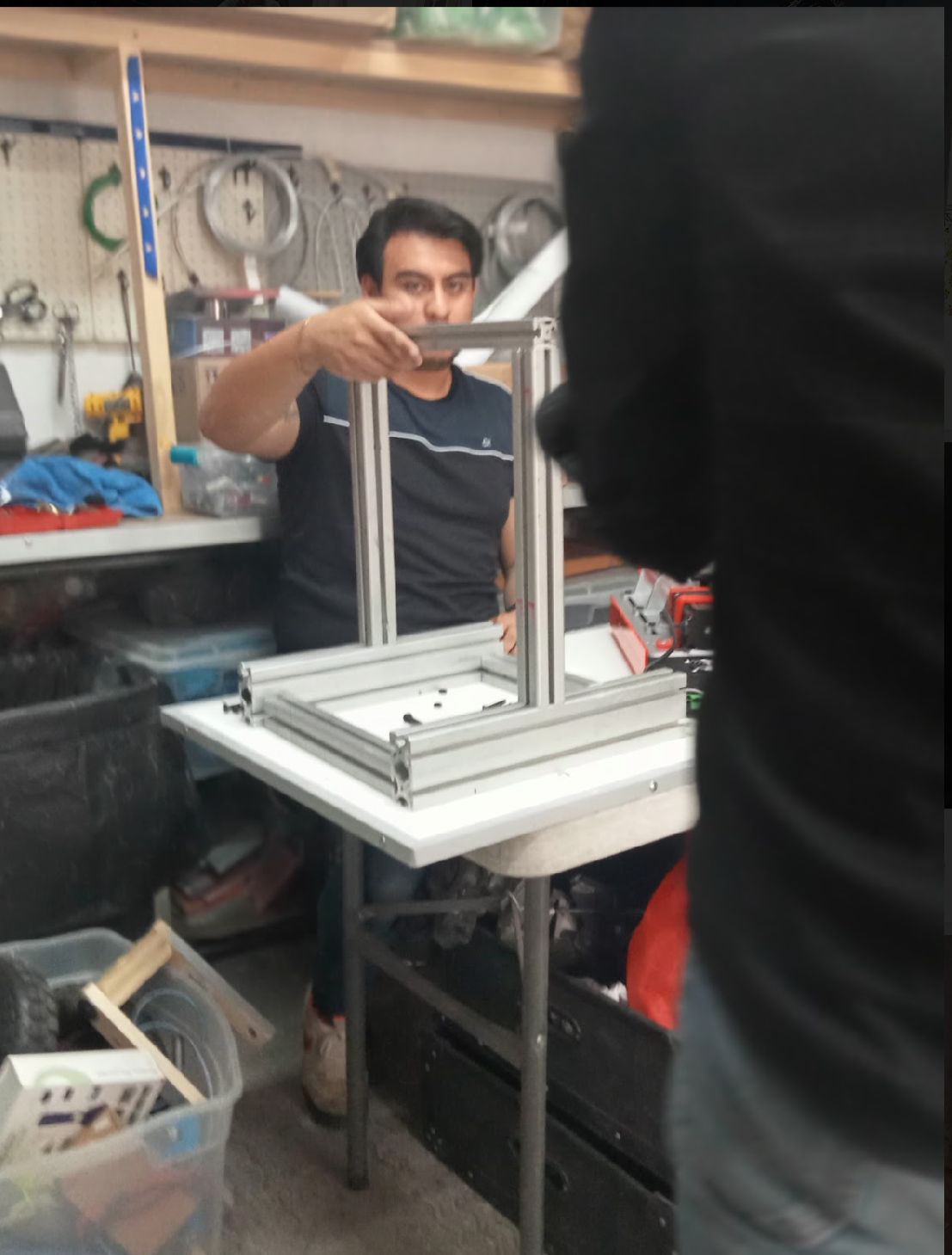
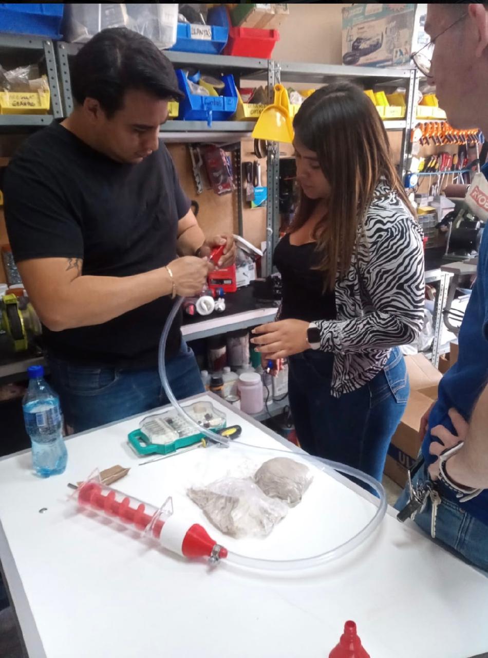
other contributions
help with machining and assembly of the machine