1. Install the drivers/software
For using the SRM-20 we need a control software and a Driver.
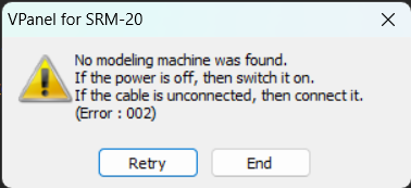
The control software is called VPanel (Click here)
And this Driver
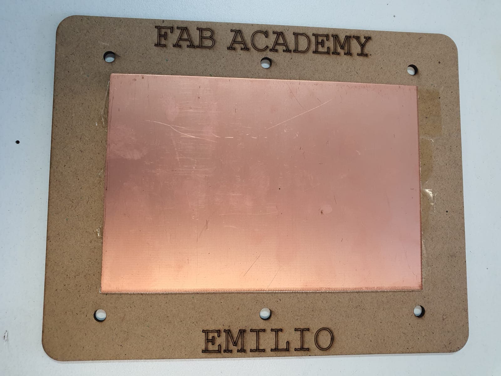
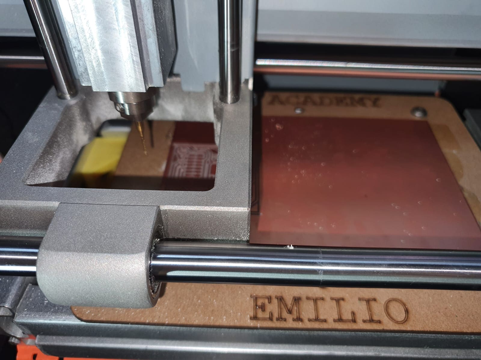
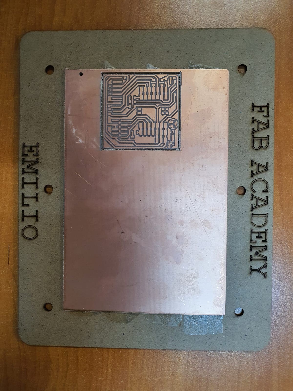
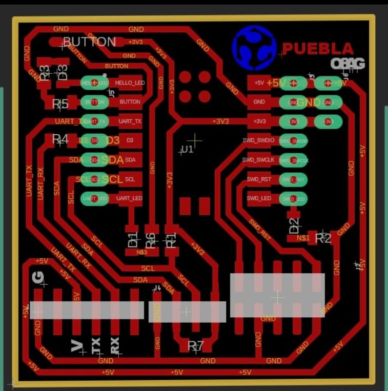
This week I learned to make PCB using a milling machine and perfect my soldering skills. You can review the Group page in this link.
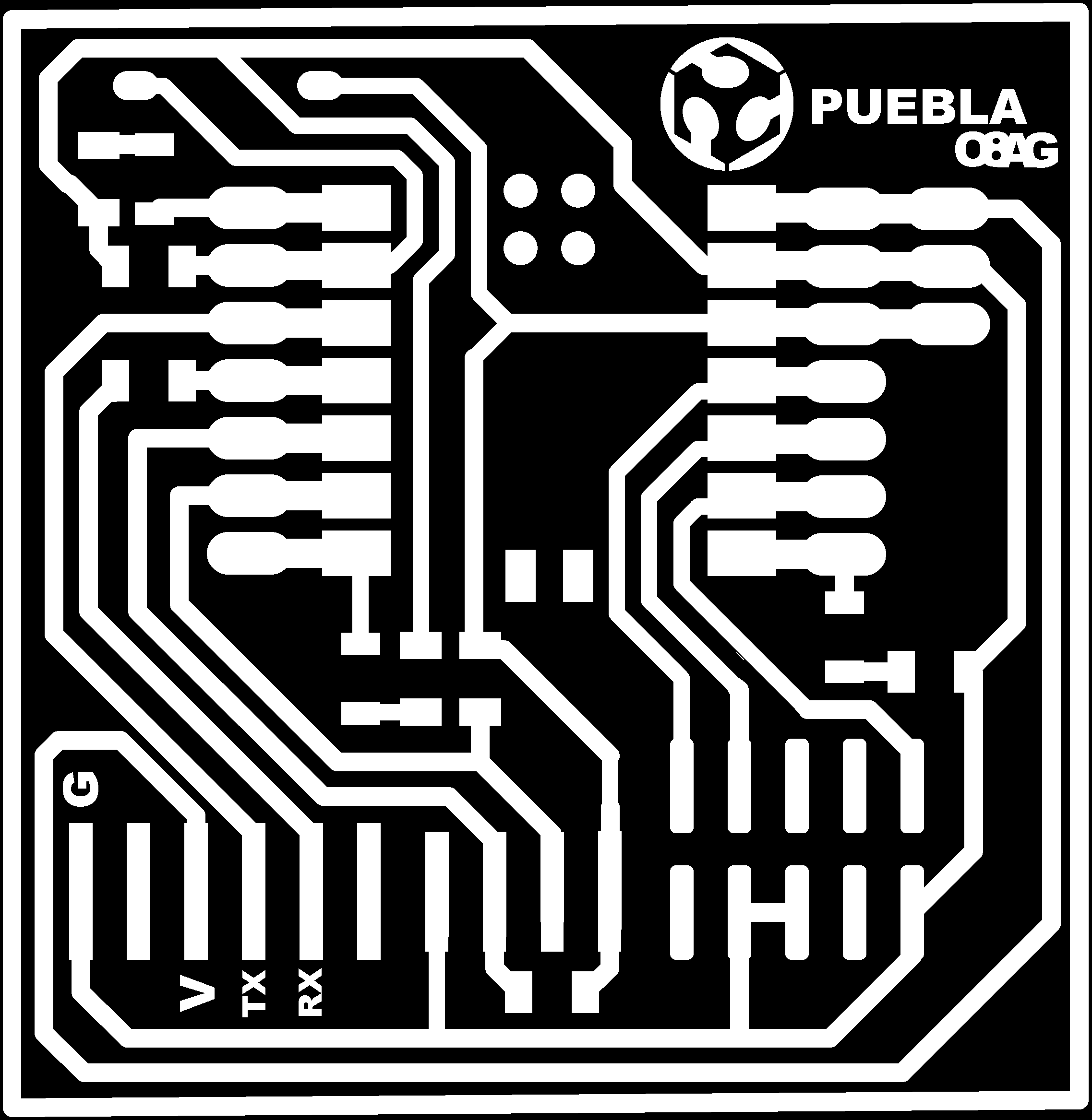
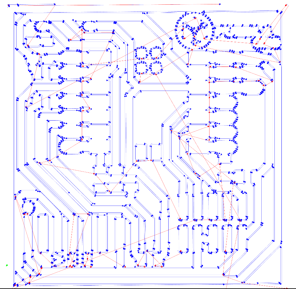
For making the files compatiblle for the machine (.rml) we will use the software called Mods.
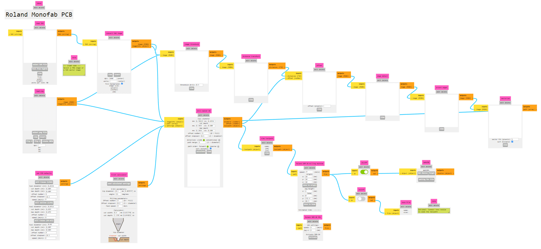
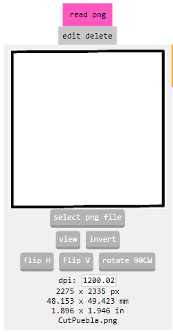
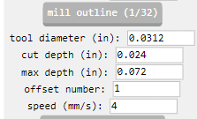
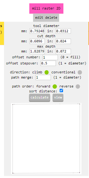
Now that you have the files you can start preparing the milling machine.
Steps
For using the SRM-20 we need a control software and a Driver.
The control software is called VPanel (Click here)
And this Driver
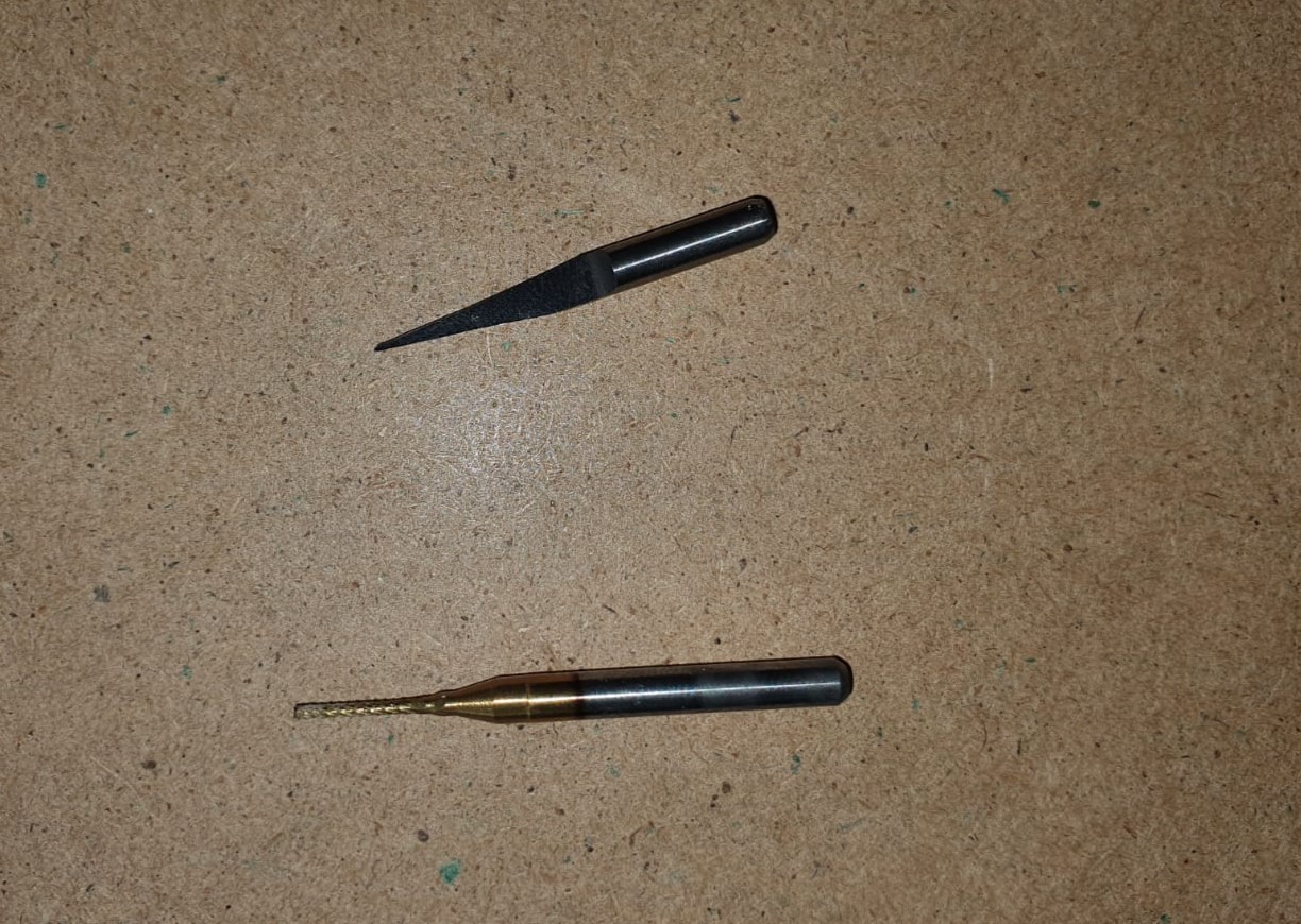
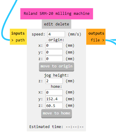
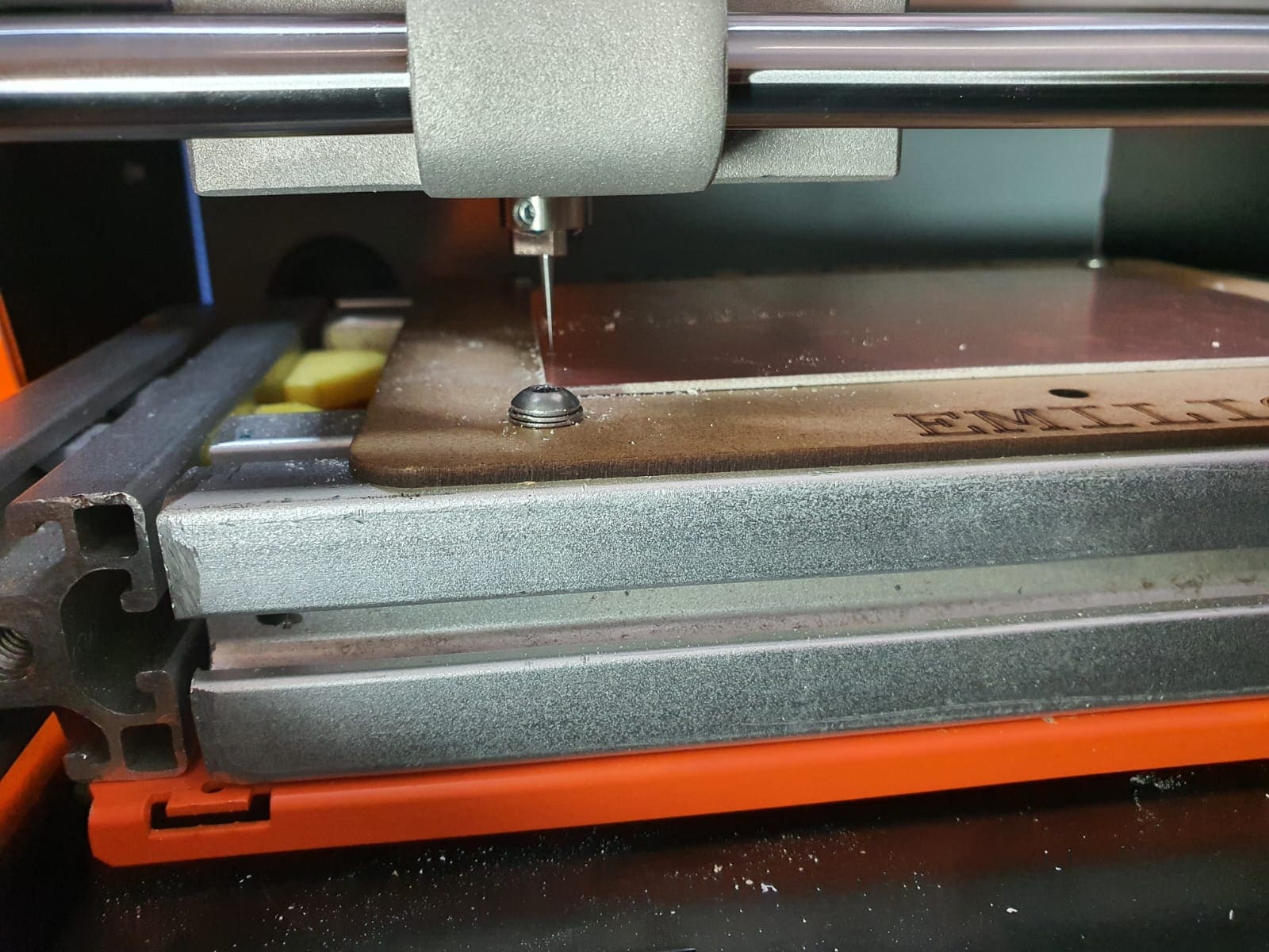
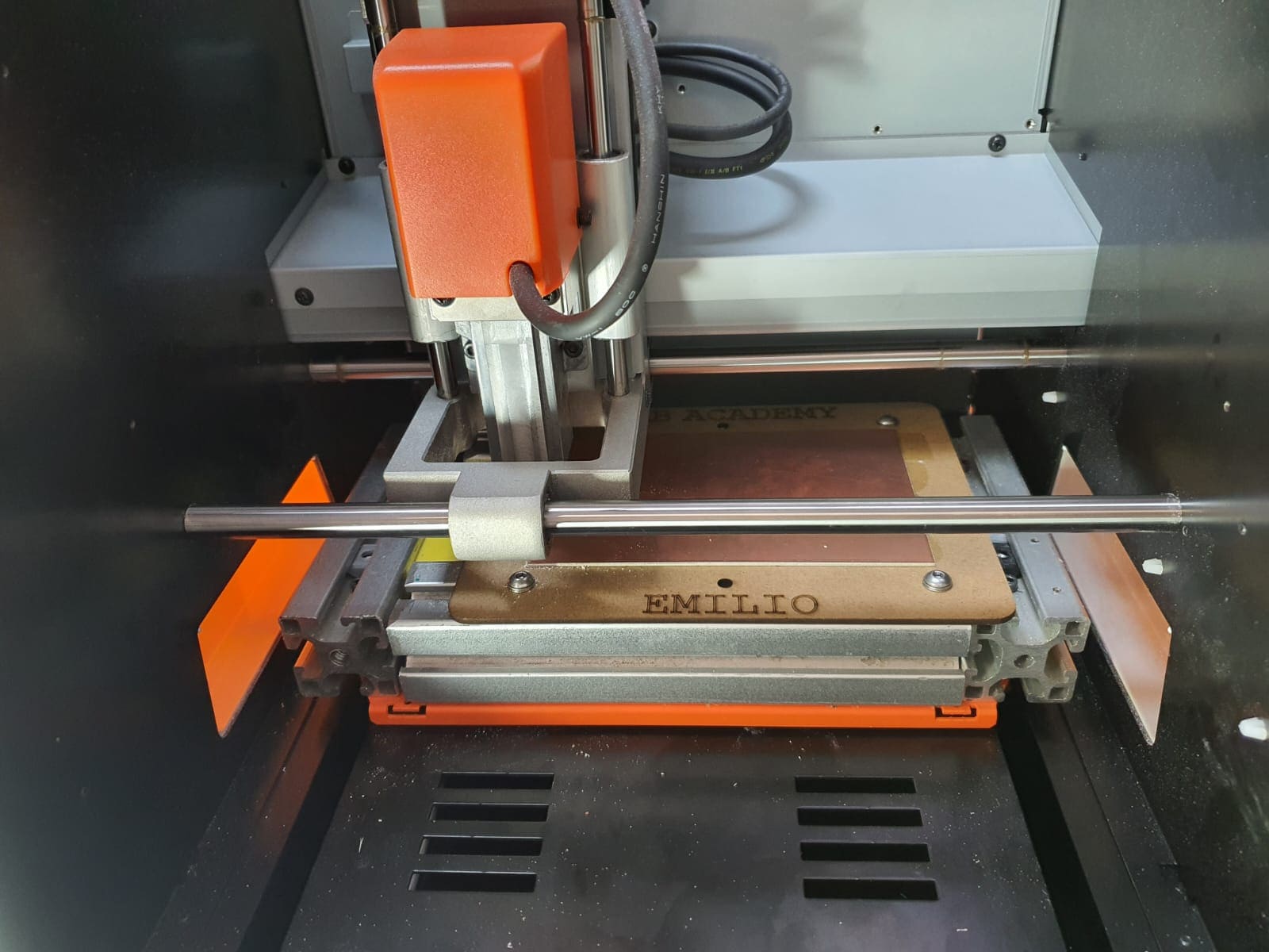
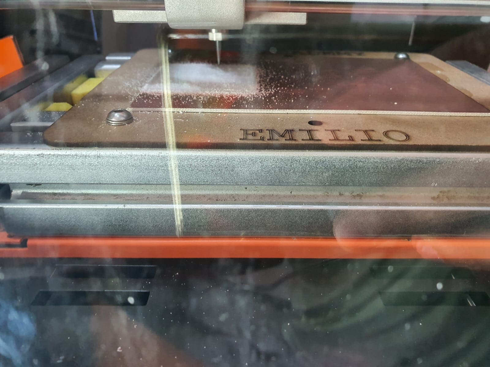
We are going to use a 15 degree V-bit for engraving and a 0.8 mm end Mill for cutting.
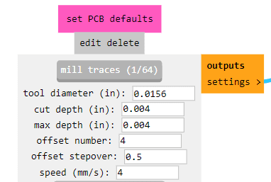
We can move the axis by clicking the arrows, set origins X/Y and Z on the top right of the
screen, turn off/on the spindle, move to the origin in the bottom and in the center
change the aproach speed.
For loading the files and start cutting/engraving is in the Cut part, in there you
can add the engraving file (complete the process), delete the engraving before adding the cutting
file.
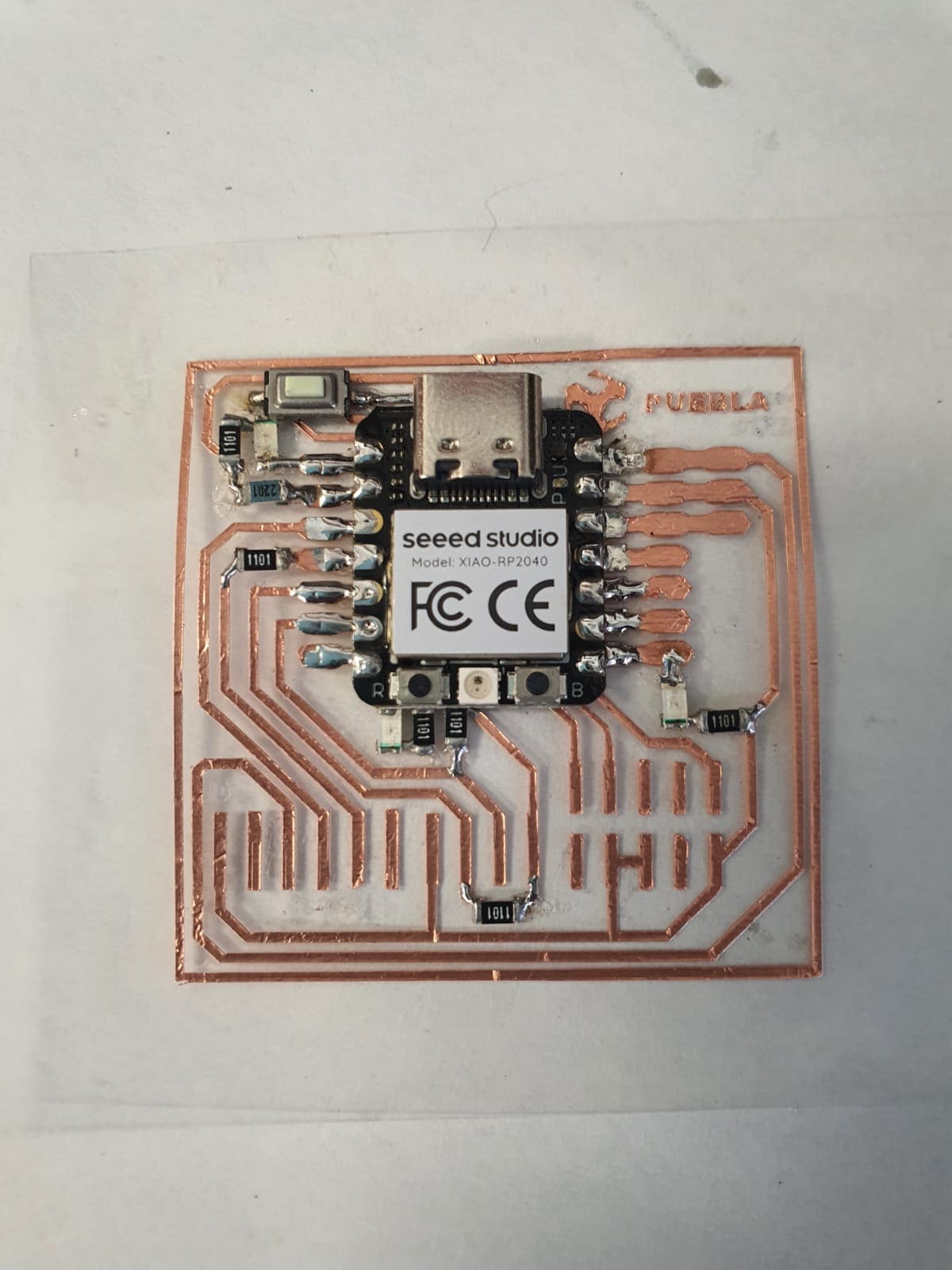
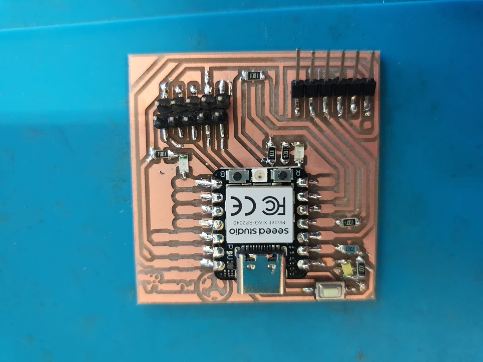
It's been a lot since I solder so I practice soldering on a test board.

After we solder and verify everything is well, we can connect it to a computer, open Arduino and load a code (follow steps).
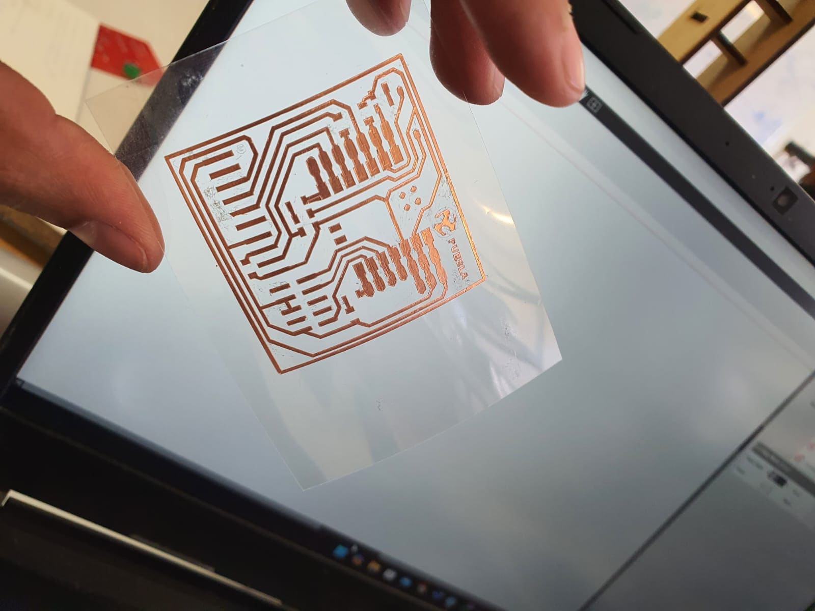
For my Final Project comfort is a very important part so trying and getting used to felxible circuits is essential.
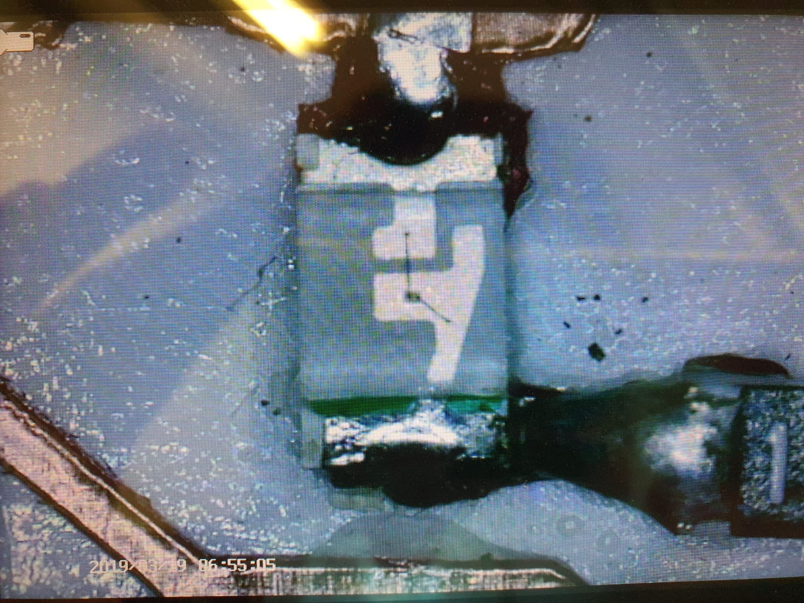
After making a lot of test with different speeds, depths and pressueres this is my conclusion:
Only Copper
This was a complete FAIL in all the way, no matter the parameters it always get ripped off and start
creating a bulk of copper.
With Vinyl
This was great at first with parameters of pressure 15, speed 2 and depth 3. It got all the cupper and Vinyl Cut
and was kind of easy but when we get in the soldering part the heat ripped of and lose the Vinyl adherence.