

Computer Controlled machining (AI Generated by ChatGpt)
Controlled machining refers to the precise and regulated process of shaping or cutting materials using machinery with a high level of automation and precision. This process is commonly employed in various industries, including manufacturing, aerospace, automotive, and electronics, among others. The primary objective of controlled machining is to achieve accurate and repeatable results in the production of components and parts.
Group Assignment
The Kannai team as usual was divided into two and i worked with Ahmad Tijjani Ishaq The task is to test runout, alignment, fixturing, speeds, feeds, materials, and toolpaths for our Large CNC machine as well as carry out safety training. Our documentation can be found at Our group assignment page
Individual Assignment
All source files can be found Here at the side bar.
For the weeks assignment, each student is tasked to make (design+mill+assemble) something big
(~meter-scale)
extra credit: don’t use fasteners or glue
extra credit: include curved surfaces
This weeks activity is a very important one to me as i used the opportunity to make part (box) of my Final Project. There are lots of processes taken to achieve the purpose of the week. Individually i worked with CNC Router ZN1325 and also shopbot.
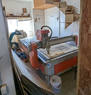
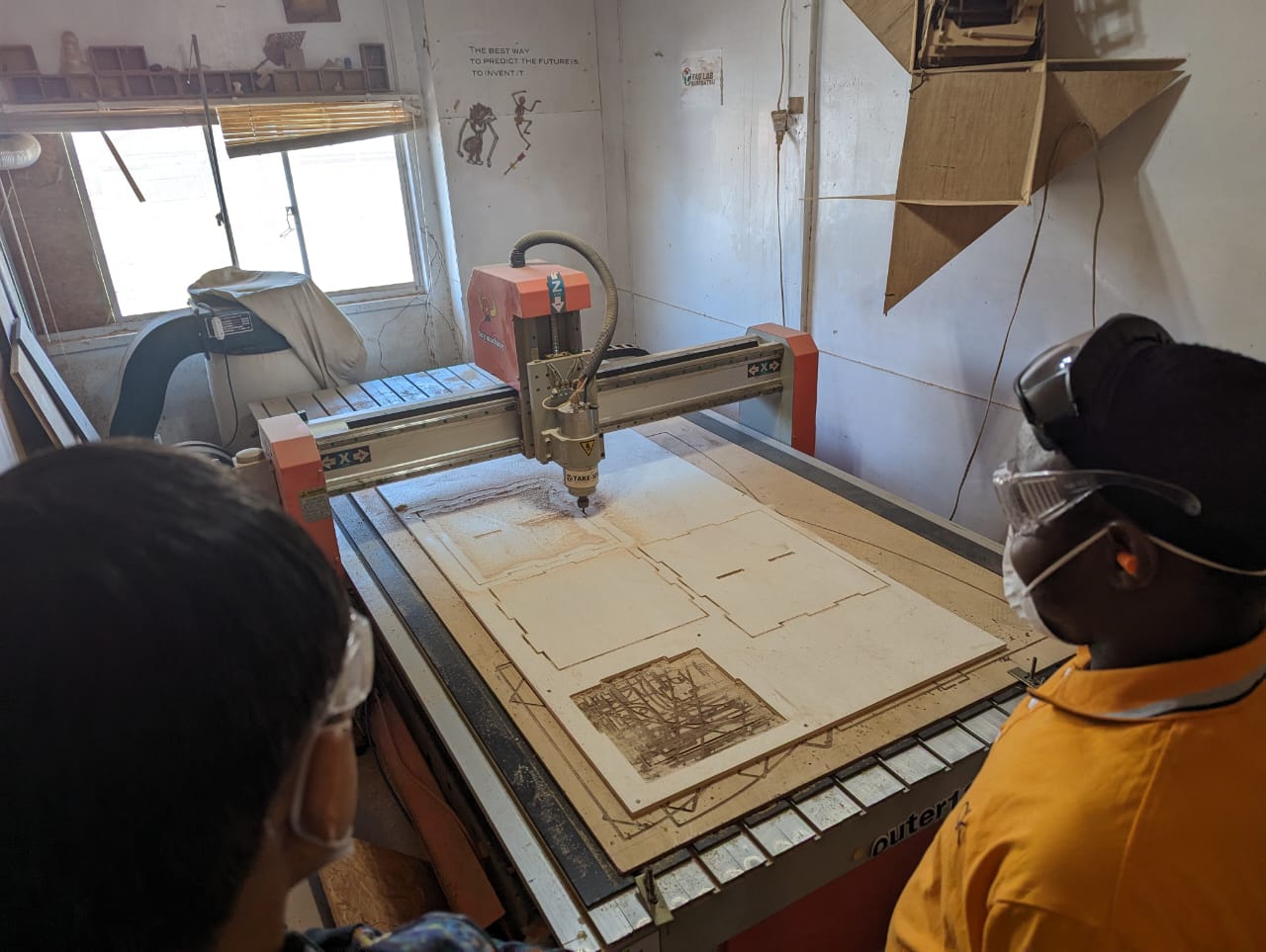
CNC Router ZN1325 ( final project box version 1)
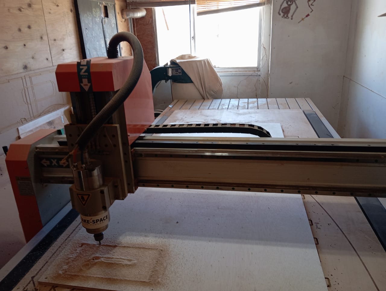
CNC Router ZN1325 machine are chineese based cnc that excell in routing , cutting, drilling and milling operation. I follow the following processes to make my box.
-
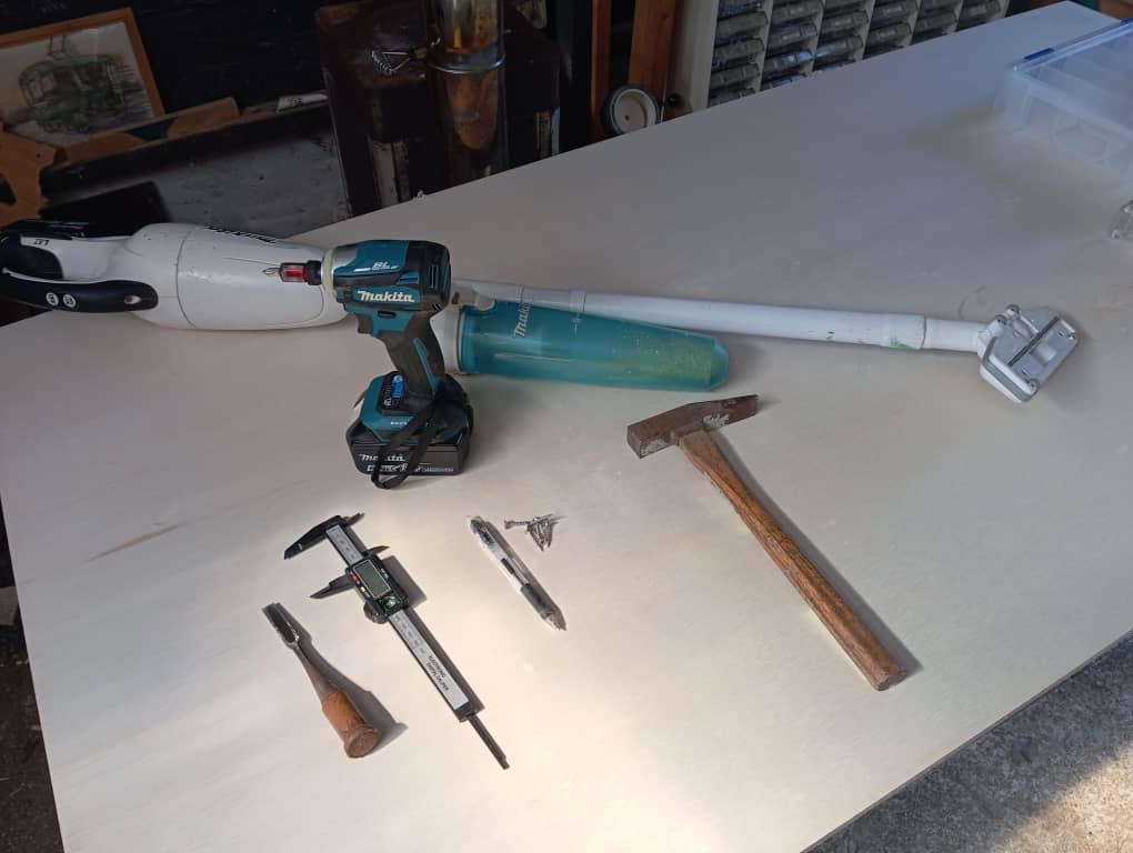
I was introduced to the tools that i will use in th process, tools such as
- mallet
- Vacuum cleaner
- measurement ruler
- vanier calliper
- marker
- Hand drilling machine
- Hammmer
- chissle/li>
-
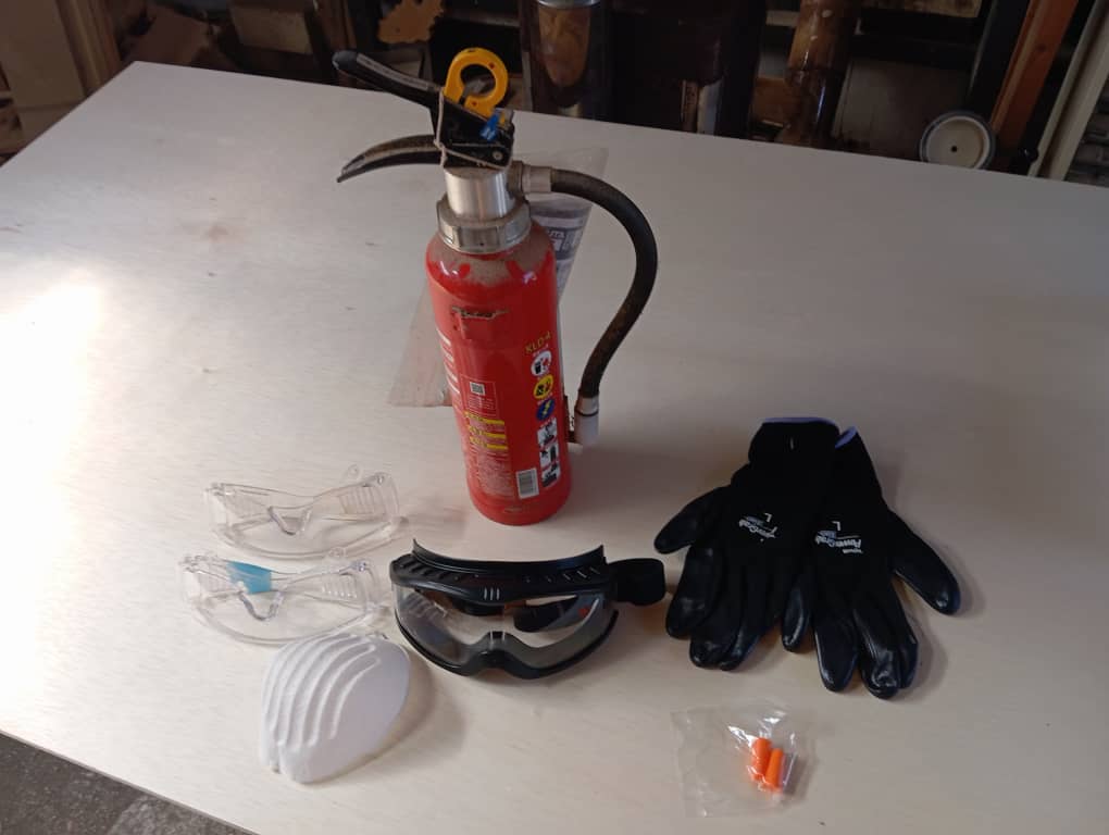
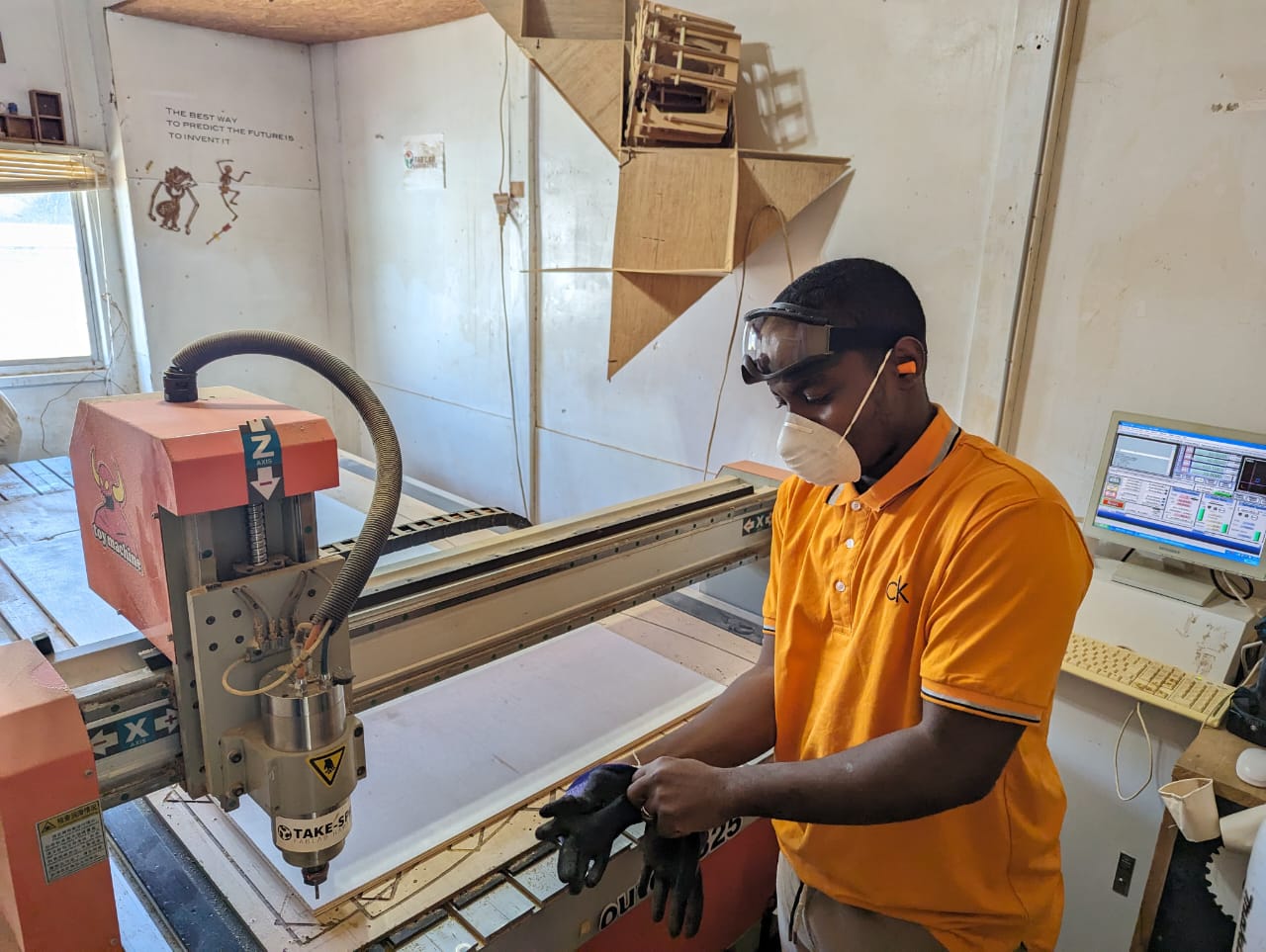
I was also given safety wears such as:
- Gloves
- Eye glasses
- Nose cover
- Ear cover
- Fire estinguisher
-
Before i commence operation, my instructor gave me some safety tips so as to prevent
accidents or injuries some of which are:
- Always stay around the machine when in operation.
- Be vigilant, keep your your cursor on the stop button of the mache 3 software.
- There is an emergency stop button, always be ready to hit when a problem is observed.
- Keep workpiece surface free from dust/wood particles as much as possible to prevent fire gushing due to friction.
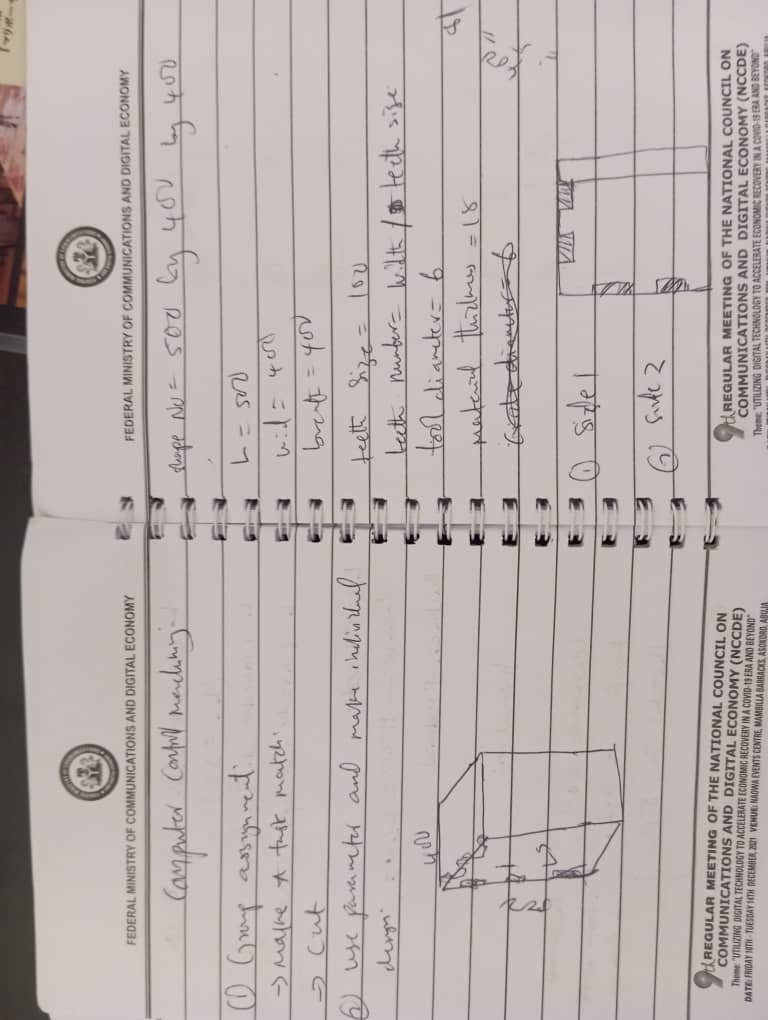
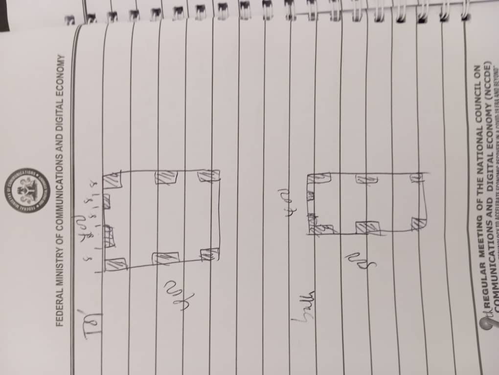
- My Final Project is a Locker with biometric system, Hence
i designed the box. I started by rough sketch on a paper and i put down the following:
- The final shape
- values of the sizes to be used as a parameter. The box is of 500mm height, 400mm width and 400mm breath
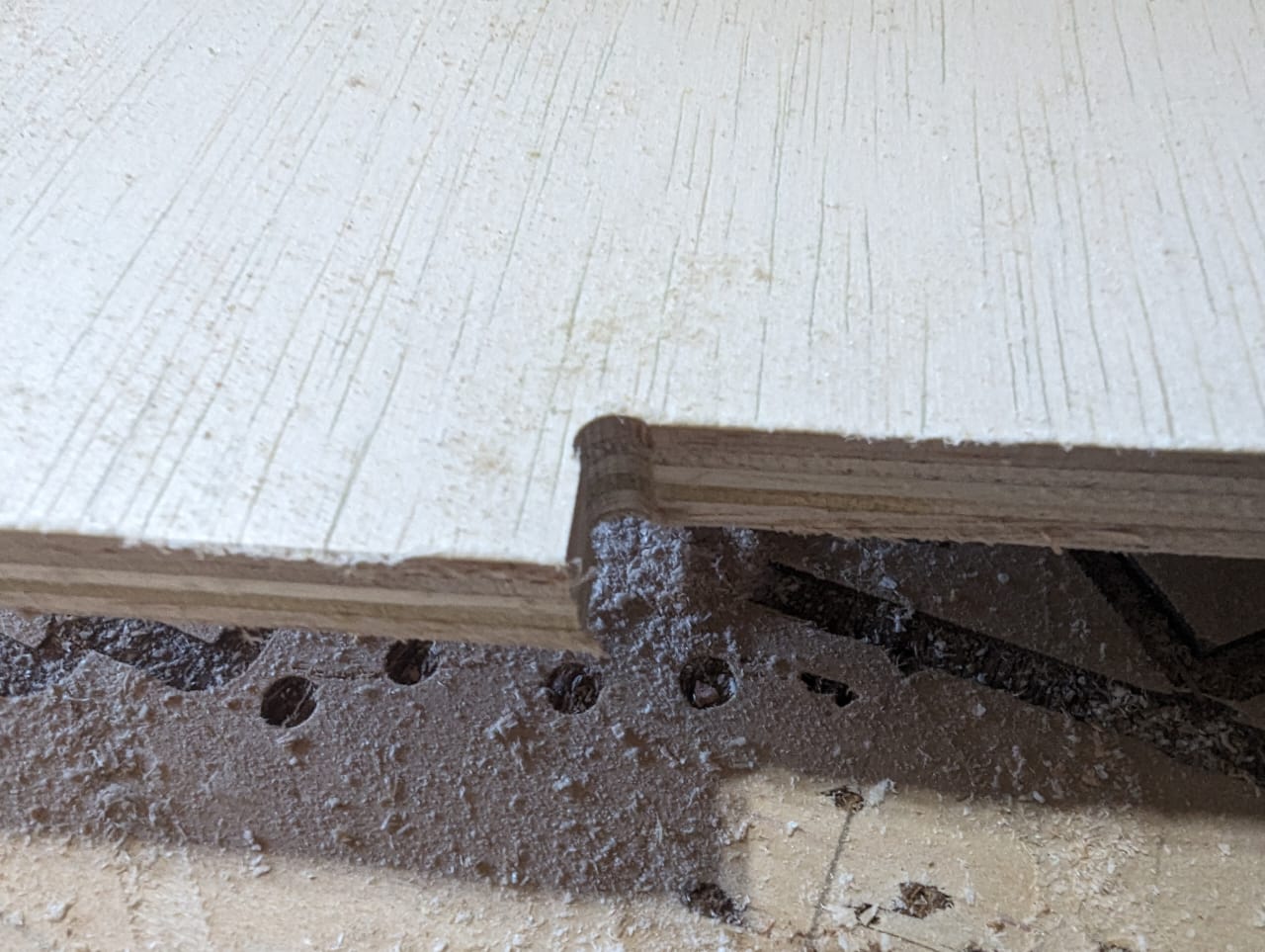
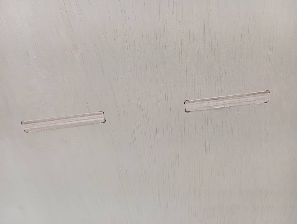
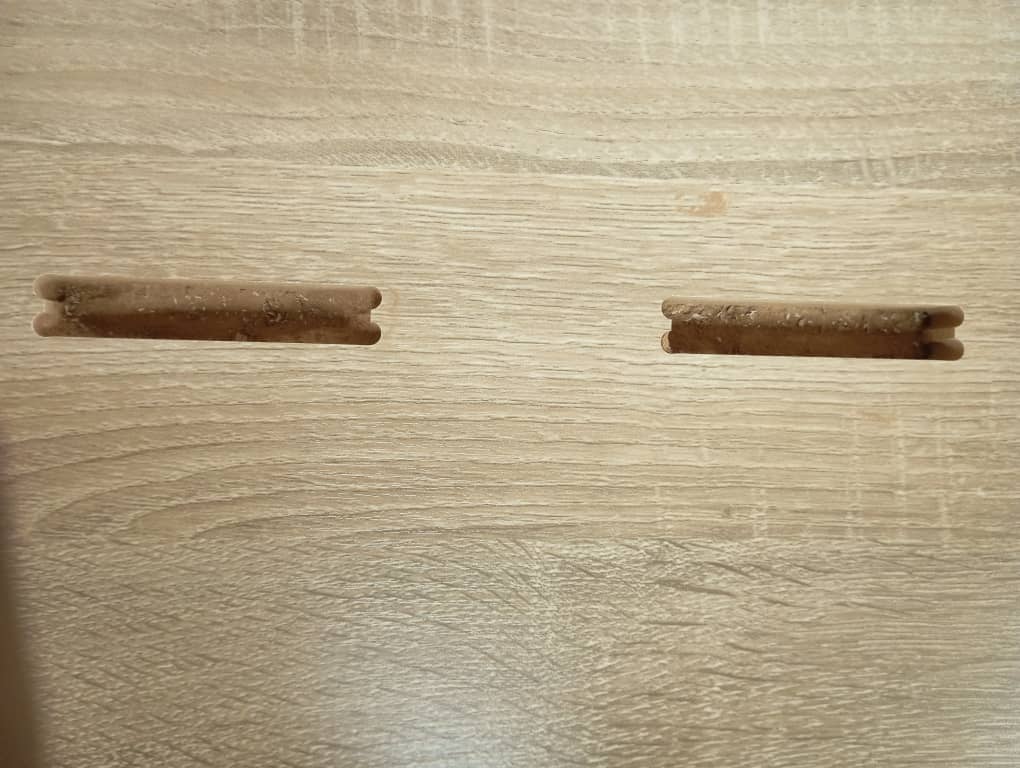
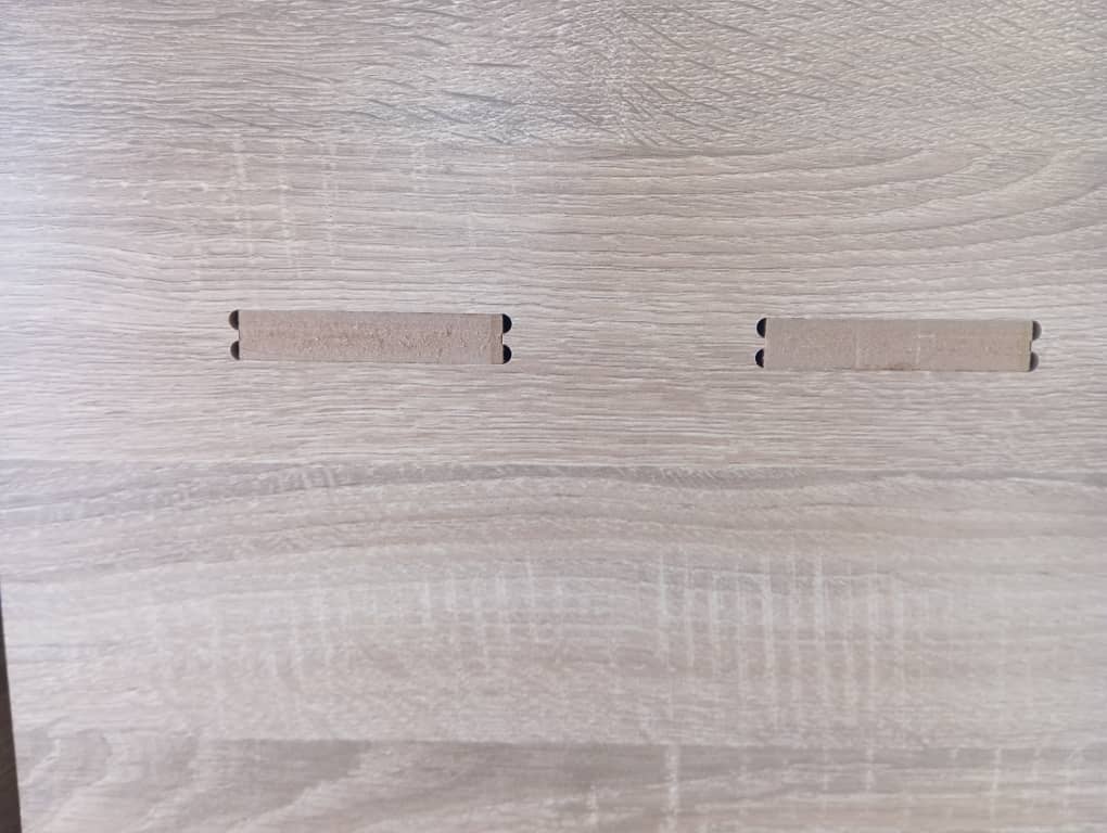
- Possible possitions of fingers and dog bone.
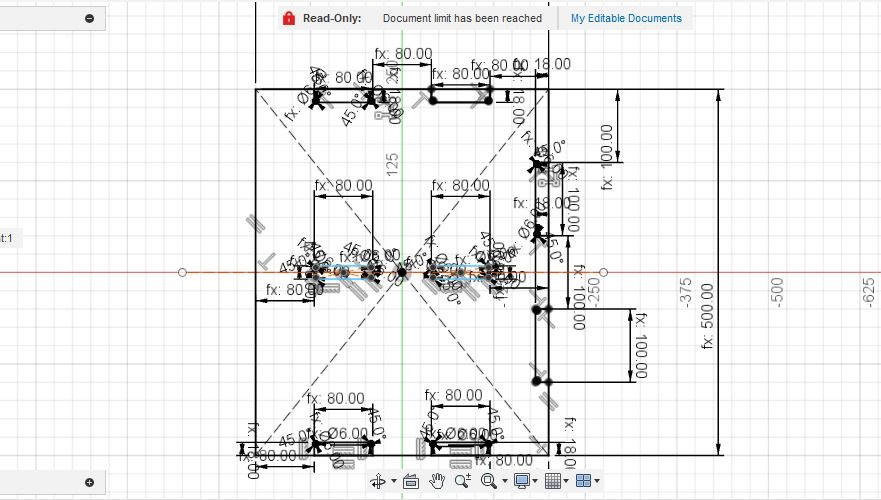
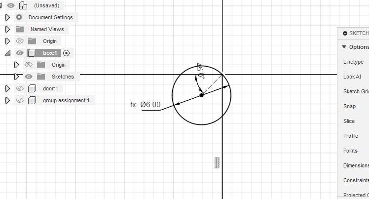
- Then I proceede with the design proper in fusion 360. There are many kinds of dogbone designs but two are common:
- The T dogbone
- The traditional dogbone
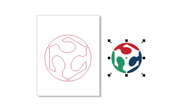
- Upon completion of my design, I exported the faces of each file using the shapetools plugin. Then i opened in illustrator and saved as .ai which can be imported into cut 2d software. At the moment i dont have screen shot and file of Adobe illustrator due to my pc's low processing capacity which limits number of apps i install but i share that of corell draw.
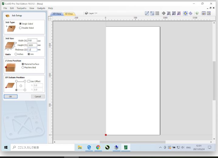
- Cut 2d software is a gcode generating software that enables us to generate the patterns and operation type for our cnc machine. More on how to use cut 2d can be found In this page and i used it to generate a profile cut gcode for my designs.
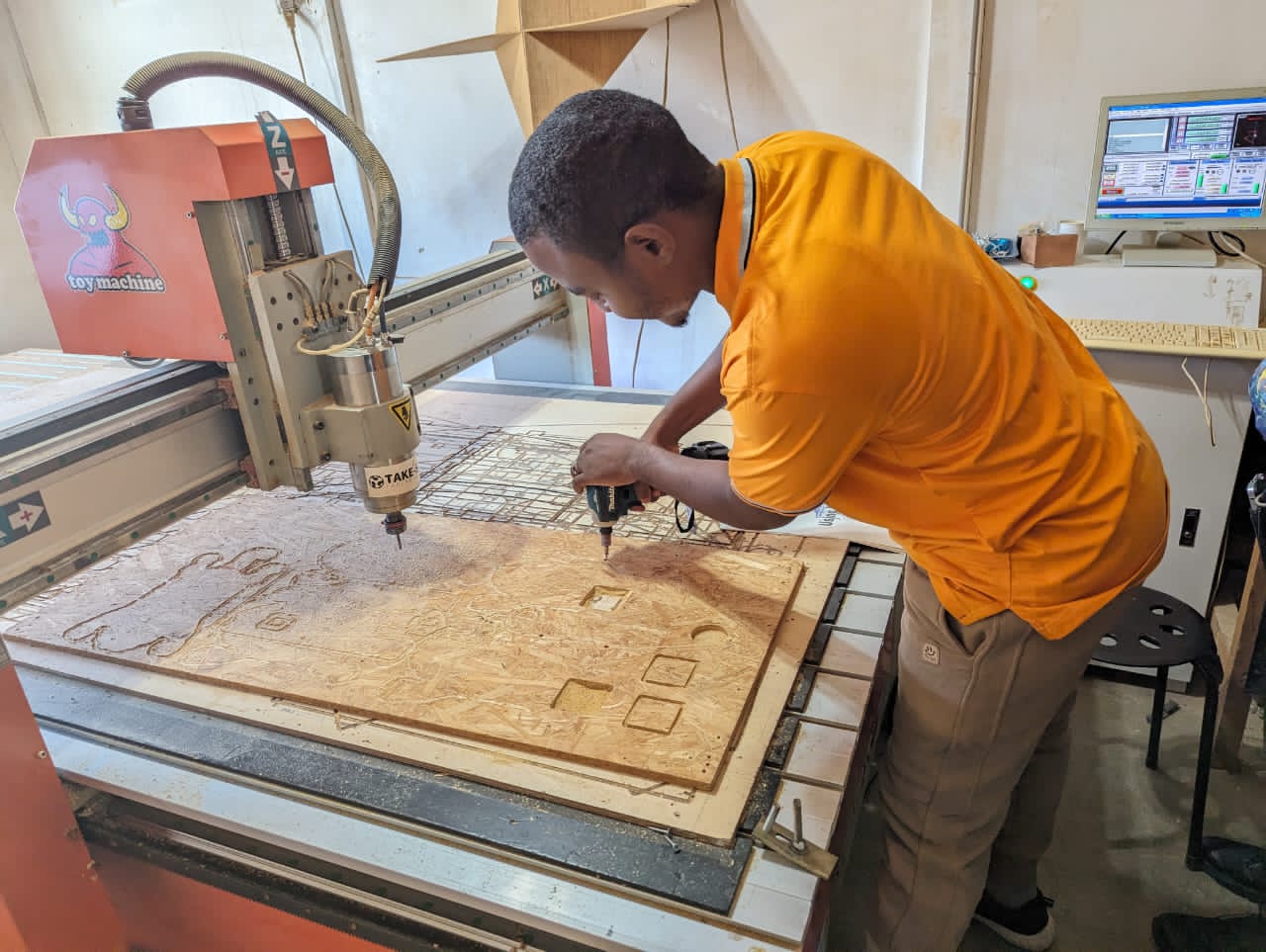
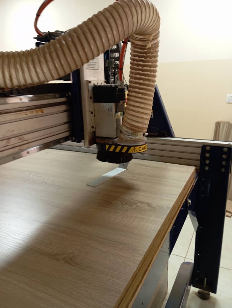
- Designs are now completed and gcode generated. Next i Prepared the the machine and work piece for cutting. I unscrew the old work piece and placed a new 12mm thick softwood on the machine bed, i fastened it with a screw.
- In order to control the CNC i use the mach3 CNC software which is used to load gcodes, as well as move the machine on different axis for origin setup (x,y, and z axis zero point ). More on how to use This softwarer can also be found here
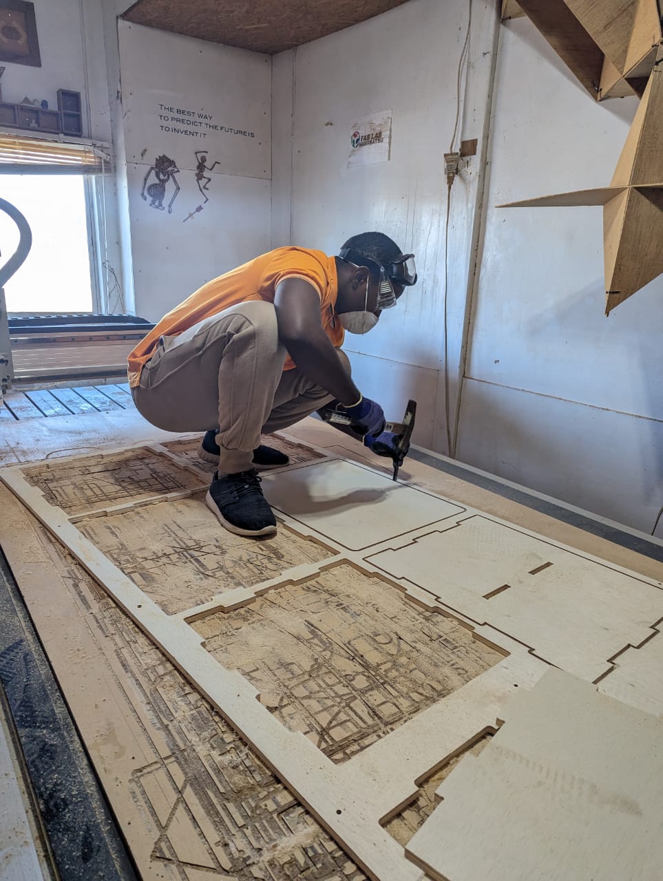
- After setting the zero axes for both x y and z, i loaded my generated gcode and started cutting
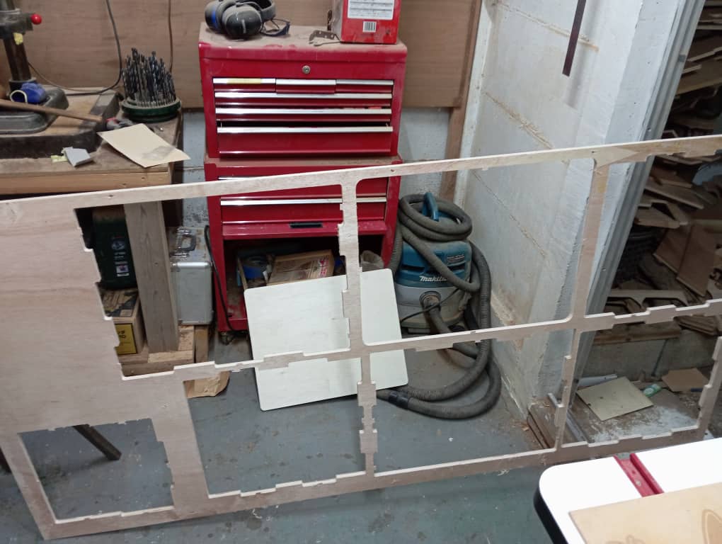
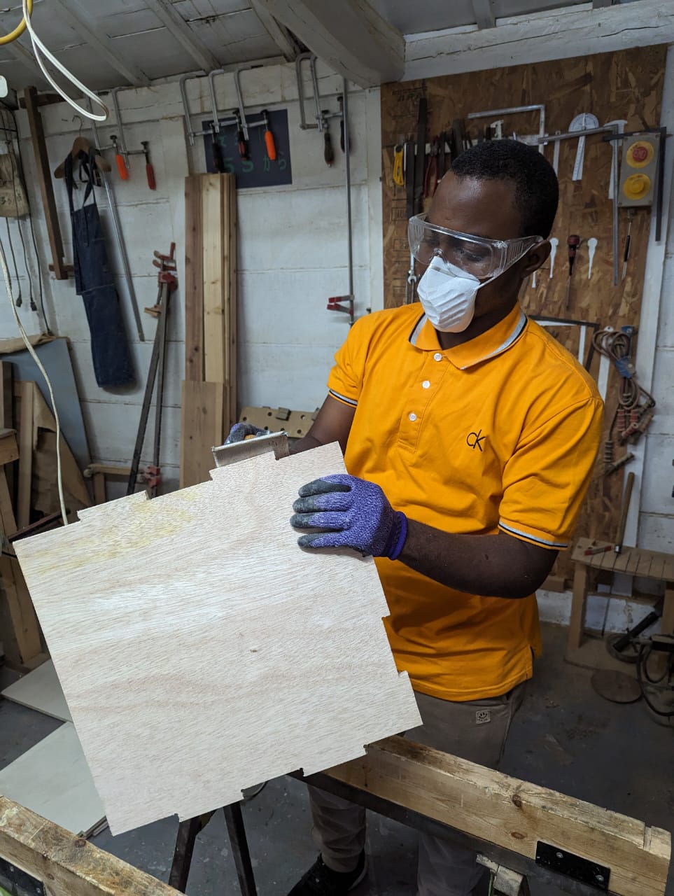
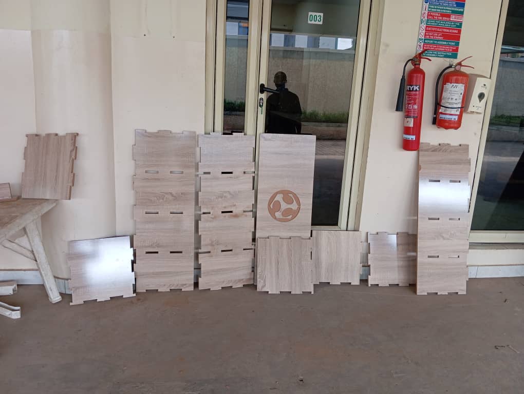
- With cutting completed, I removed all parts from the bed and unscrew the work piece.
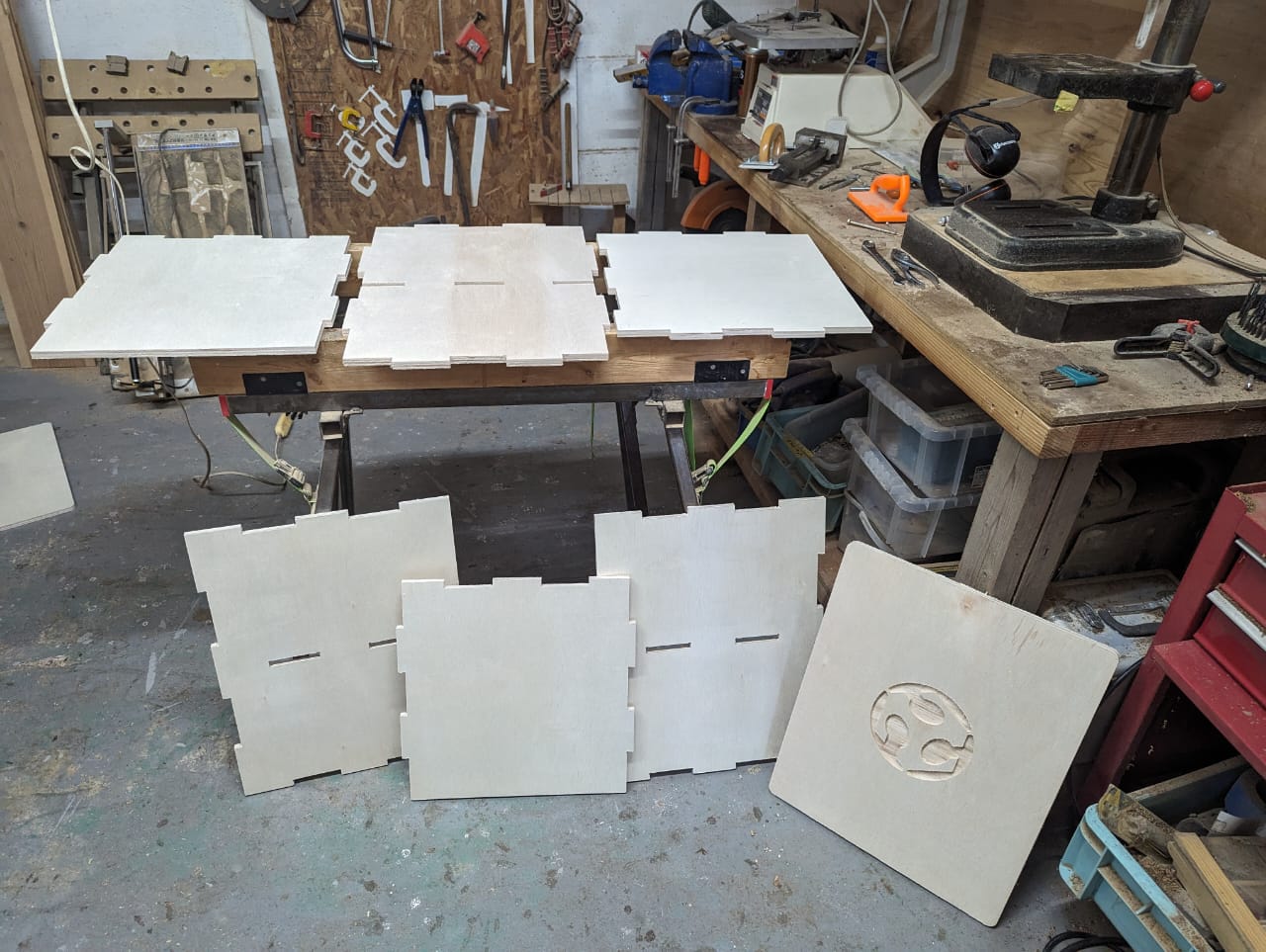
- A little sand papering is done to remove extra wood particles that forms due to cutting from the edges of my shapes.
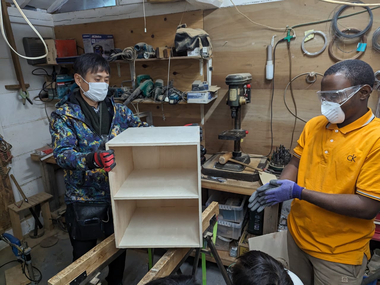
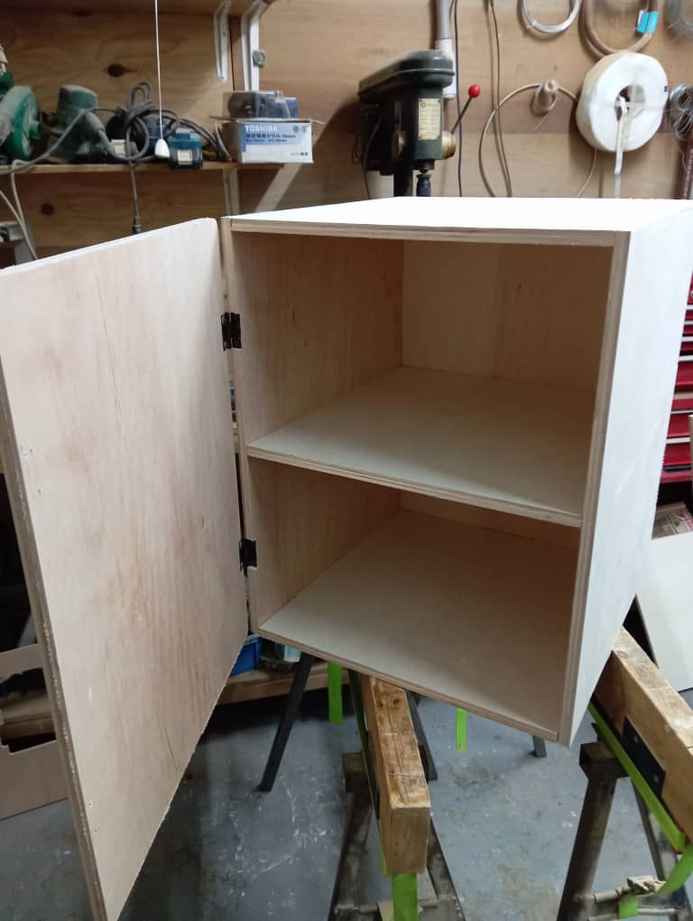
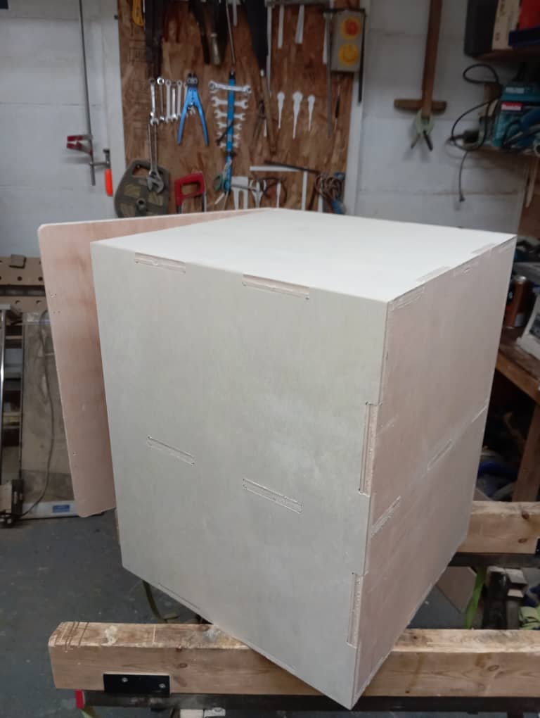
- with that completed assembly began, with no glue or fastner the shapes meshed perfectly well and form a strong box, ofcourse The dogbobne helped alot as the shapes fits with ease but grip tightly.
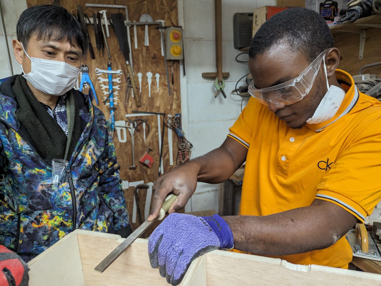
- To install the door, a hinge connector was used to fix the door to the body and to do that, i had to use rough file to chip off parts of the box body to accomodate for the 5mm thickness of the closed flaps hinge. Other wise the door wouldnt lap on the box body.
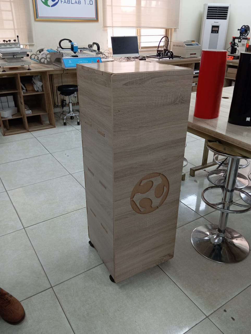
- My final project version one wooden part (box) is now completed.


All source files can be found Here at the side bar.
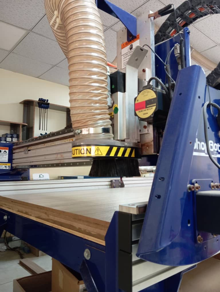
ShopBot ( final project box version 2)
I decided to make a version 2 of my final project box, so that i can keep one at each of the
two labs i worked in ( Fablab kannai Japan and Abuja Fablab 1.0 Nigeria)
For the second version i am making it twice the height of the version one and i am using shopbot
CNC for the cutting operation.
The processes i follow are the same as that of the version one, and software used are similar or the same such as:
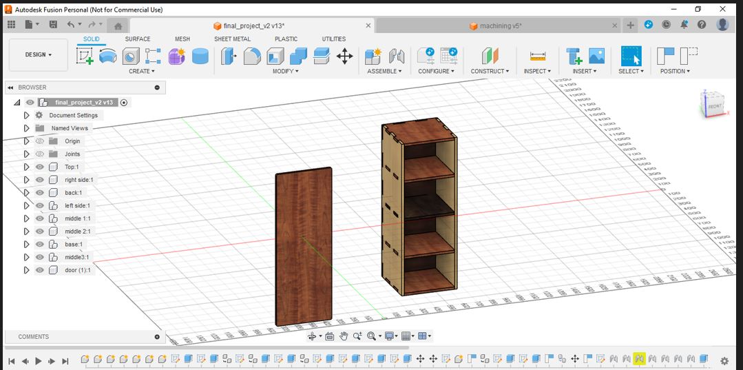
- fusion 360 for 3d modelling
- shaper tools plugin for exporting faces as svg
- Corel draw for exporting as dxf
- Aspire software which similar if not same as cut 2d for generating gcode and patterns
- shopbot3 software for controlling the shopbot machine which serve as mache 3 software earlier used
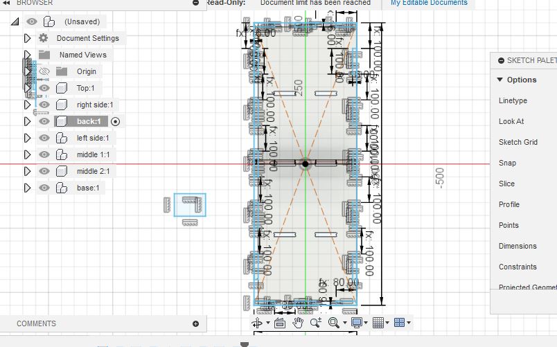
Design
As usual before using the machine, i started by making my design so as to obtain cutting data. I follow up similar design process as i did in version one as follows:
- I made a sketch on paper of the various parts/shapes to be cut out, and i also decided
the following parameters:
- Thickness of material= 16mm
- height of box = 1100mm
- width = breathd = 400mm
- Then i proceeded to design proper in fusion 360. I used the T dogbone. this time around.
- All faces of parts were then exported as svg using the shaper tool plugin
- I used corel draw to remove color fill and then Export the designs as pdf ready to be used in aspire software, Other extensions were not working well except for bitmap and pdf. I chose pdf
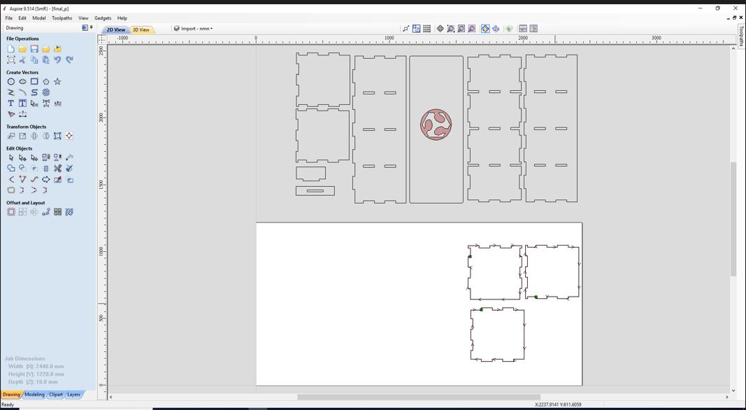
- cutting data (gcode) was generated using aspire and the process is explained below. for more infomartion on
how to use aspire browse through this.
- start the software, start a new project, setup the workbench and origin
- load the pdf file
- Place the design at appropriate possition
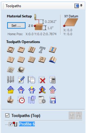
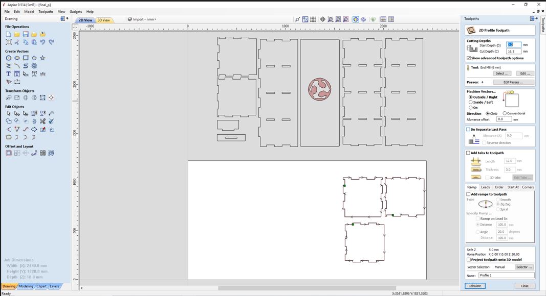
- click the toolpath tab at the right hand corner
- Select profile and set the following data
- cut depth = 0 to 16.5mm (so that tool can cut through my 16mm thick wood)
- tool = 6mm
- passes = 4
- Machine vectors = Outside/Right
- Add Tabs , edit tabas and place tabs in the desired places
- change the name and then calculate
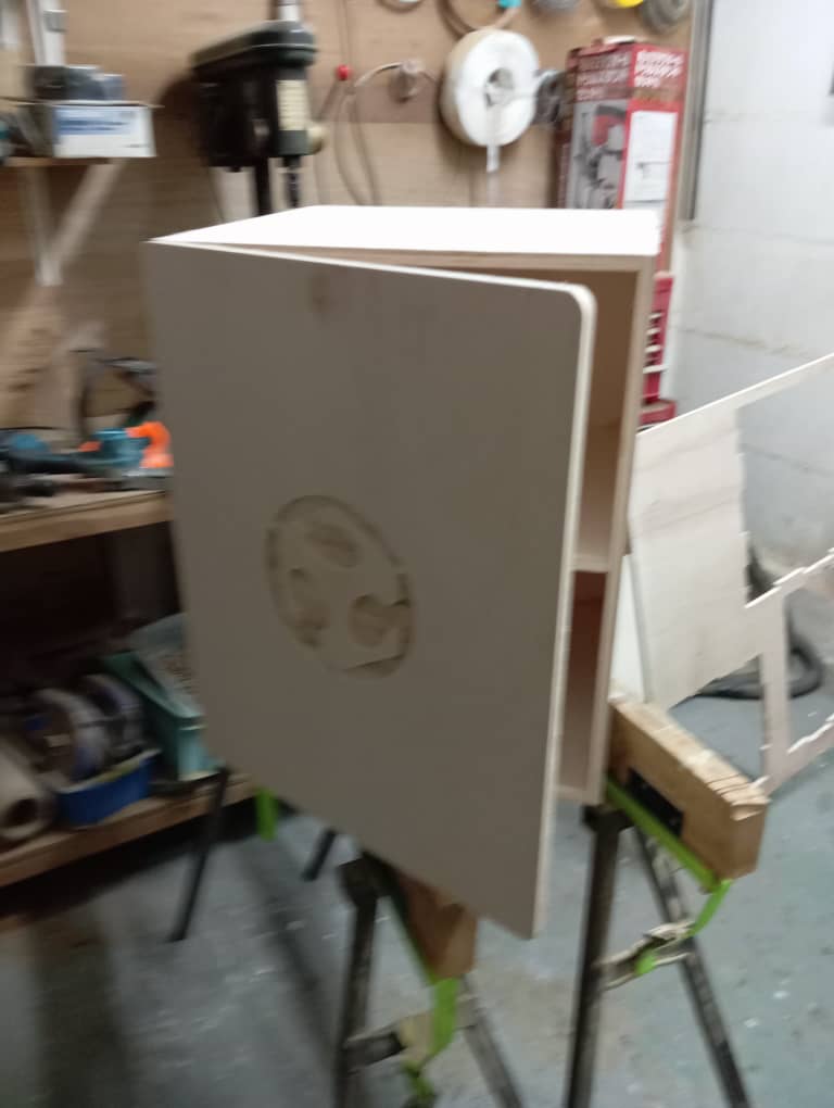
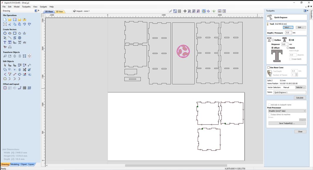
- similar process for engraving the Fabacademy logo
- Select the fast engraving type of tool path
- set the desired depth and tool diameter (dmm depth and 6mm tool)


Preparation of machine bed
With design completed, i moved on to prepare the workpice and machine bed before cutting, i did the following:
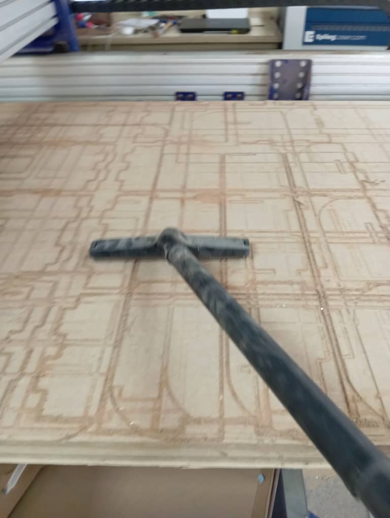
- I cleaned the machine bed using a vaccum clearner
- I placed my workPiece (MDF) on the machine bed.
- I secured it fix firmly with a nail gun
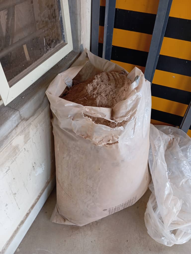
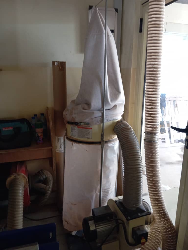
- Then i changed the dust collector bag because its filled

Cutting Process
Cutting process involves the following.
- launching the shopbot3 app
- setting up x,y zero by hitting the X,Y zero button for automatic zeroing
- setting up z axis zero by:
- Moving the maching head manually with the x y arrow in the software onto the material (workpiece)surface
- placing the z zero metal plate found on the machine head directly below the milling bit on the surface of material
- Then clicking the z axis zero, The maching tghen automatically carry out the zeroing process and gives out prompt that are to be followed.
- Once the z axis is completed we return the plate to its possition
- We then load the g code generated by aspire and the start cutting

Assembly
With the cutting process completed we then remove all the parts and assembled by meshing the parts according to design.
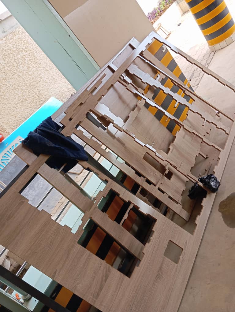

We observed that holes are exposed as a result of the tbone we made, so I 3D printed parts to fill them.

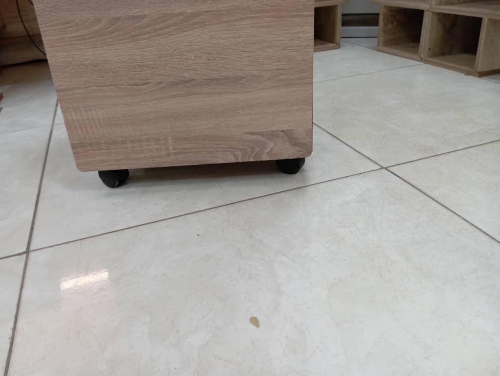
A hinge is used to connect the door to the body and Tires were attached. My final project box version 2 is completed.

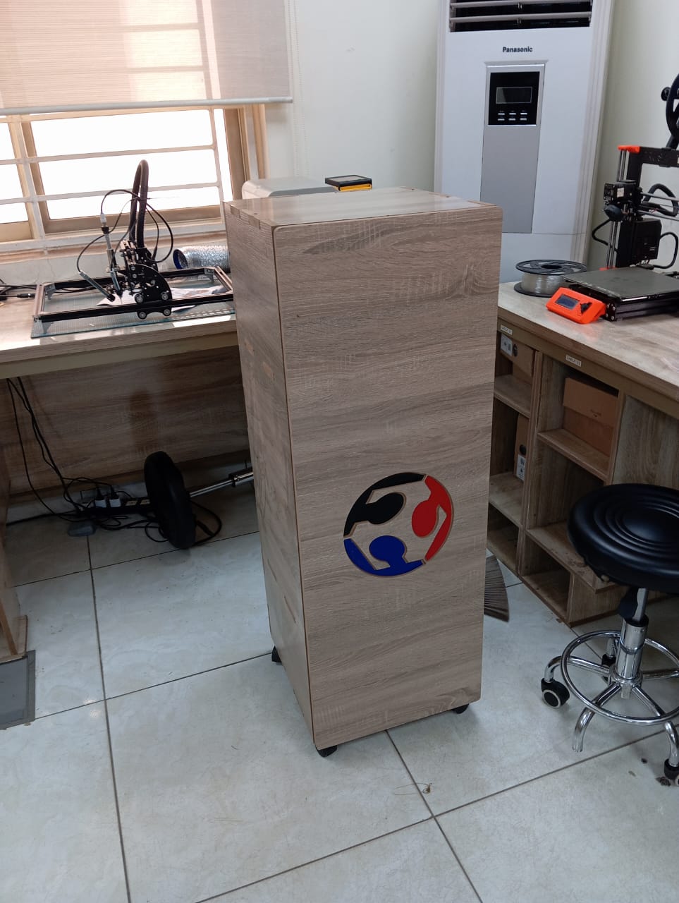
All source files can be found Here at the side bar.