

Electronics Production
Electronics production involves the realisation of electrical design into physical reality. Modern technology has immensely improved production of electrical system which has led to an even rise in global tech.
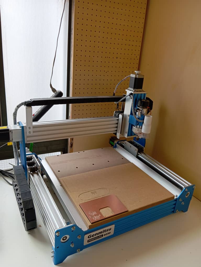
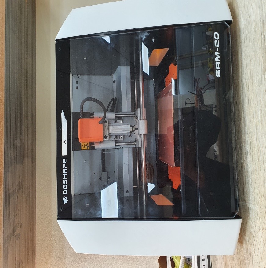
Electronics production is therefore one of the key skills being taught on fabacademy courses. There are several techniques used in electronic PCB production and for this weeks session we are working on the milling technique. Me and team used the Genmitsu ProverXL 4030 and Roland XRM 20.
Group Assignment
The Kannai team as usual was divided into two and i worked with Ahmad
Tijjani Ishaq
who worked remotely from Abuja Fablab
1.0. we did characterisation of our machines , i worked on Genmitsu and he worked on
Roland SRM20.
Detailed Explanation can be found on our Group assignment site but a few shots of the results and processes are shown below. we succeeded in using our machines to mill the following designs under guidance and direction from our instructor Tamiya San.

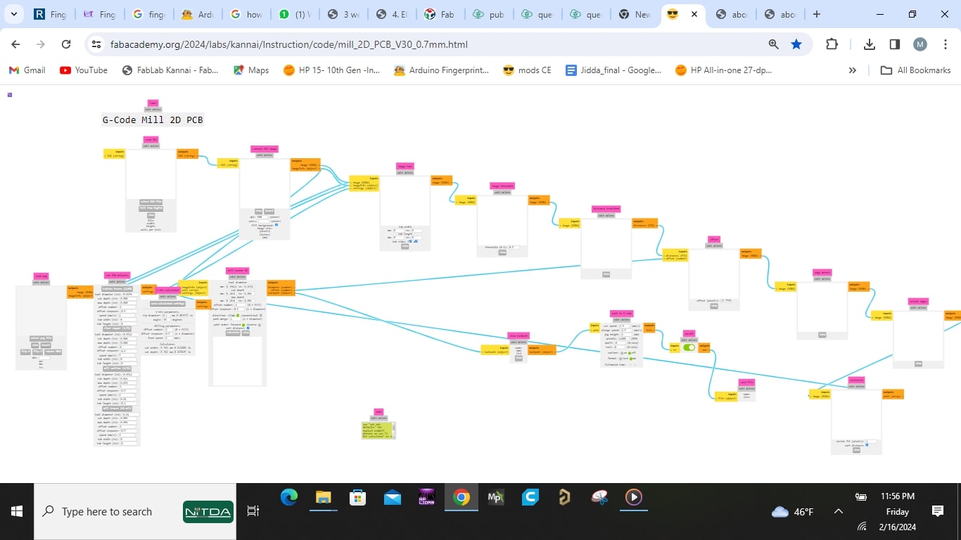
We used Mods Site to generate the gcode.

The software used to control the Genmitsu milling machine was Gsender.
And the result is as seen below
- we decided to work with vbit 0.1 tip diameter 30 degree bit for trace as it gave us a desired outcome.
- For outline and drill we got a good result with 0.7 flat end mill

Individual Assignment
All source files can be found Here at the side bar.
After successful milling of the lintest board under group assignment, we were tasked to individually mill the Quentorres board Below i describe the steps i followed to achieve the goal of the exercise using the bit we chose in our group assignment.I divided the sections into The following:
- Preparation of Milling DATA
- Machine operation (milling)
- Observation and post milling Processing
- Soldering
- Testing
Preparation of Milling DATA
Below are the processes i follow:- I downloaded the Quentorres PNG files from his website consisting of trace, drill and outline.
-
After Obtaining the already design, i then used the Mods Site to generate my code as earlier explained in group assignment, mod is used to generate gcodes to be used for milling by multiple milling machines.
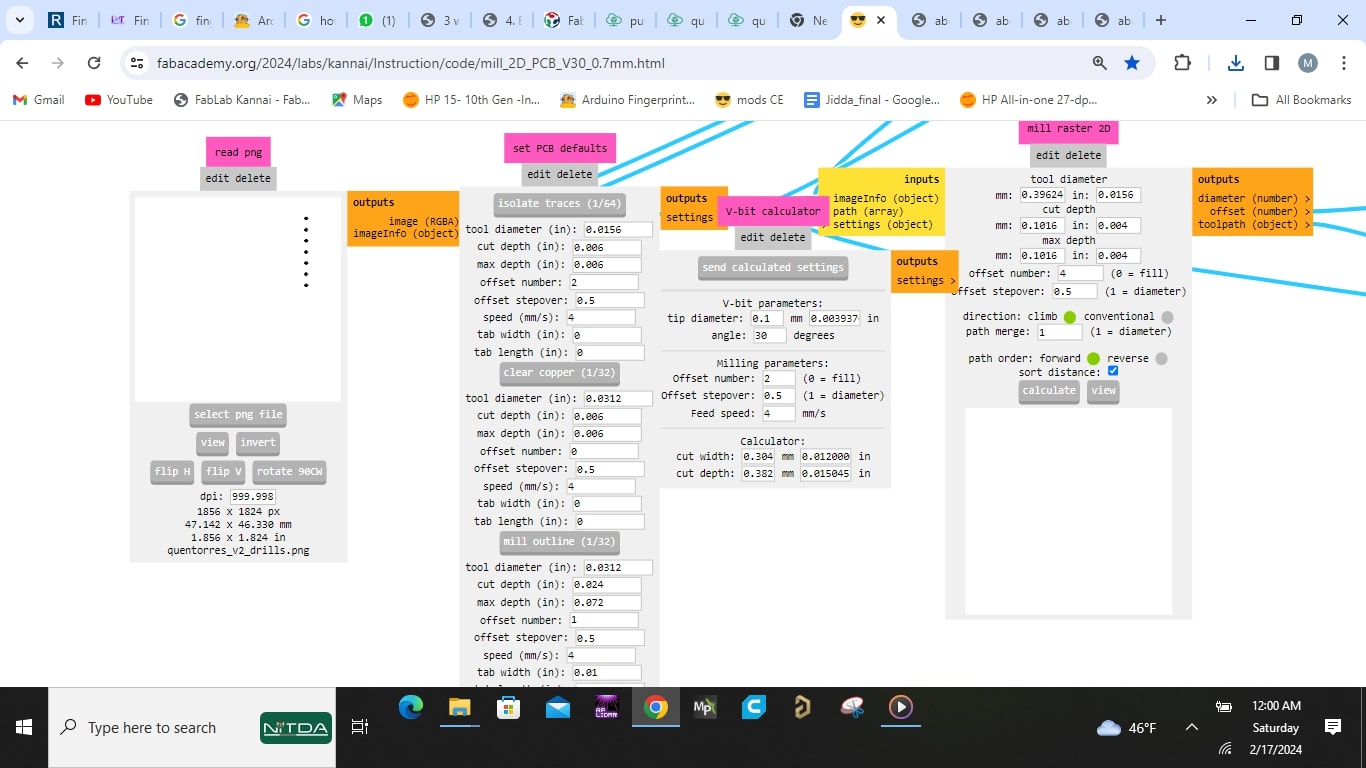
- I started by loading the Mods site
- then i imported the downloaded quentorres trace png image by clicking Select png file
- Since this is trace, i chose vbit calculator and inserted the values:
- tip diameter = 0.1mm
- degree = 30
- offset= 4
and then clicked send calculator setting. - The cutting flow now appeared in the display section under mill raster 2d as
seen in the image above
, i then confirmed the data in its section and made sure its what i sent above,
then i clicked calculate.
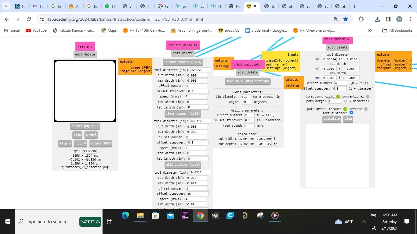
Immediately a file was downloaded containing the gcode titled quentorres_trace.nc and a view was displayed for me. sometimes one has to click the view button beside calculate to see the view. - I then repeated similar step of import png file into mod for the drill file.
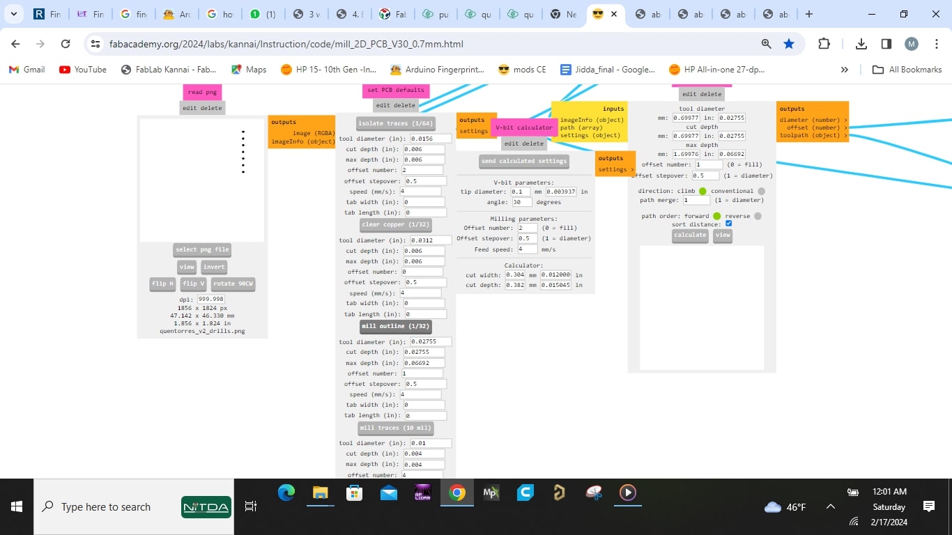
- As explained earlier, for drill and outline milling
we use the o.7mm flat end mill, so i go under
"set pcb defaults" heading and i used the section set "mill outline (1/32)" with
the following values:
- tool diameter = 0.02755 in (0.7mm)
- cut depth = 0.02755 in (0.7mm)
- max depth = 0.06692in (1.7mm)
- offset number = 1
- tab width and length = 0
- speed = 4
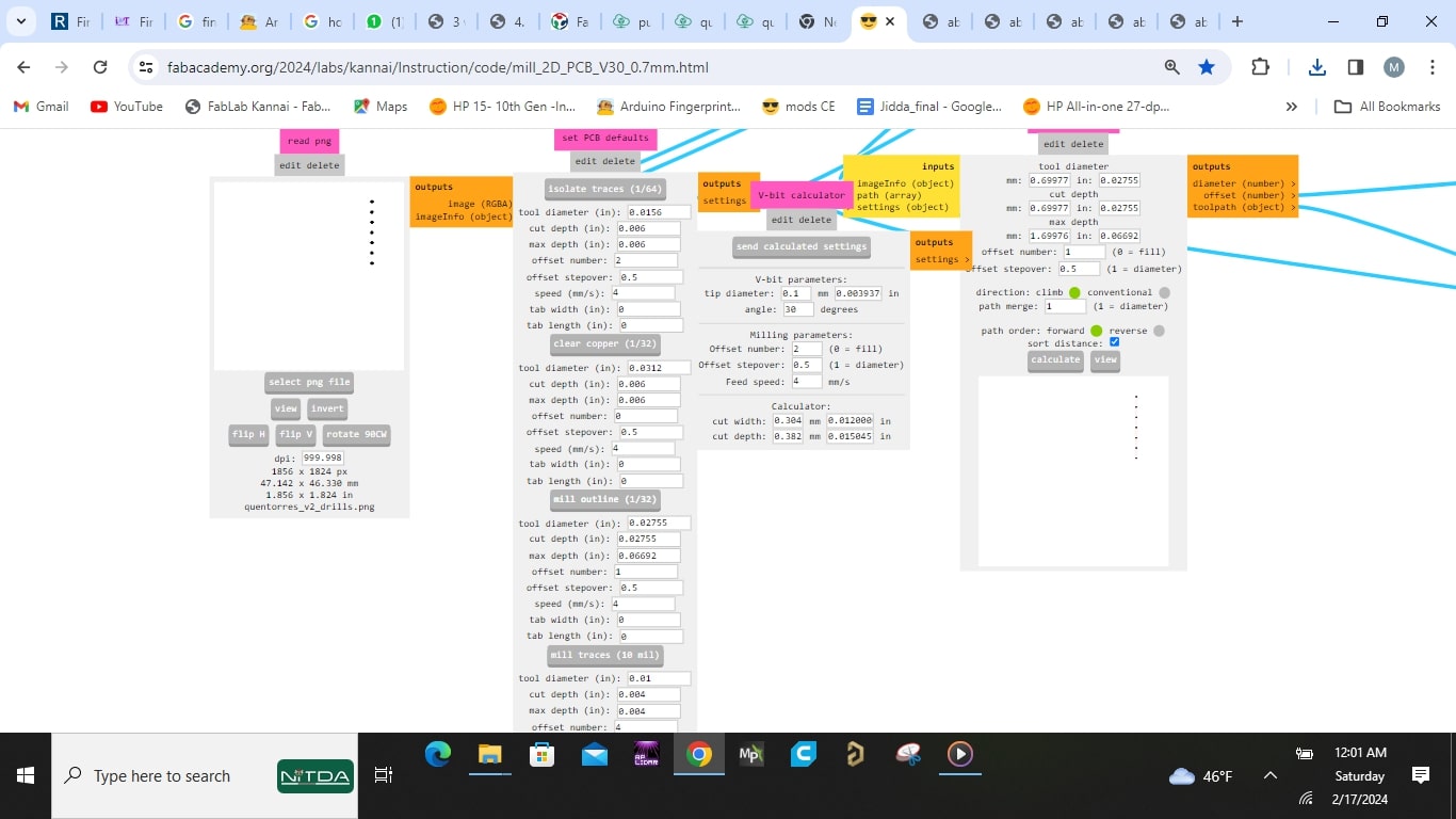
and then clicked the section header (button) "mill outline (1/32)". - After that the drill flow appeared under the
display section under mill raster 2d
, i then confirmed the data in its section and made sure its what i sent above,
then i clicked calculate.
Immediately a file was downloaded containing the gcode titled quentorres_trace.nc and a view was displayed for me. sometimes one has to click the view button beside calculate to see the view. - Similar steps used for drill was done for the outline using same bit and profile values and the results are shown below


Machine operation (milling)
I worked with Genmitsu ProverXL 4030 milling machine, it is easy to get started with and with the help of my local instructor i was able to use it efficiently and safely. With the data provided i head straight to milling room.
The processes i follow are as follows:
- I started by taking notes of safety measure taken while using the machine which
are:
- One has to be with the machine while in usage
- The machine surface and bed must be thoroughly cleaned using the vacumm pump before and after usage
- The milling bits are very fragile, one has to be extra careful when changing or handling them
- the spindle is fast and the bits are sharp, one has to stay clear from the working area of the machine when machine is milling.
- I then placed my work piece on the table, using double sided sticky tape to hold it firm and prevent it From moving while milling takes place
- I switched on the machine and connected my laptop to it
- i launched the Gsender file and uploaded the Quentorres trace file to the programs environment
- I used the x,y and z axis control on the software to come to the front access area and then inserted the vbit
- i then set my x,y,z zero , then i click start job milling then begins
- The trace milling finished and i then change bit to the flat end mill for outline and drill
- I loaded the outline and drill mill files respectively and carried out the milling
- After completion i applied paper solvent to weaken the adhesiveness of sticky tape used in keeping the board in place


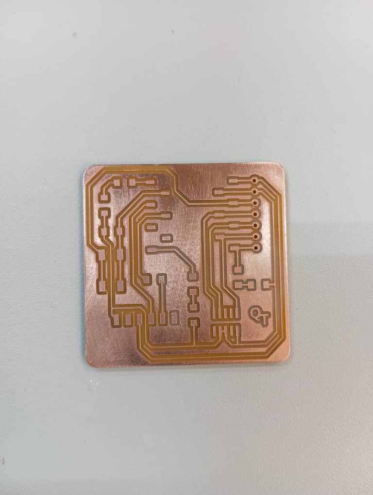
Observation and post milling Processing
It is always important to observe if there are open or short circuits. In my case every track was well traced and no circuit issues was spotted. therefor i proceeded to gently brushed off the surface with fine grain paper and then i used liquid soap to wash the board.


Soldering
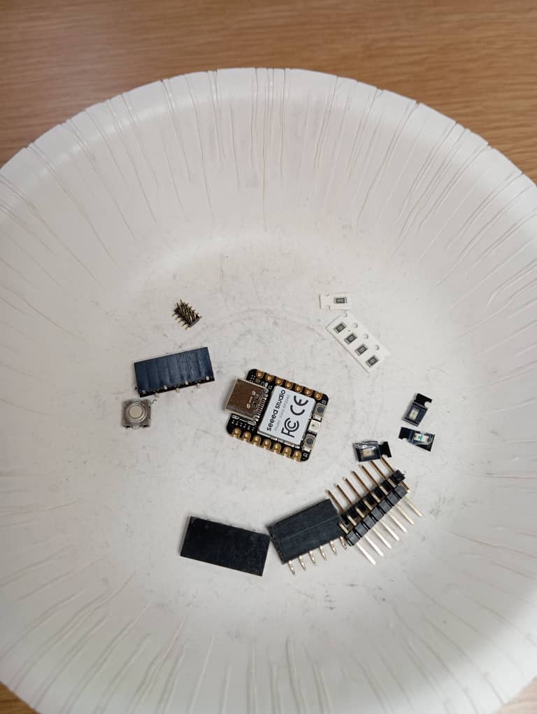
This is the process of attaching components to our board which will complete the process and make it lively. i therefor did the following:
- I gathered all the components required for my board
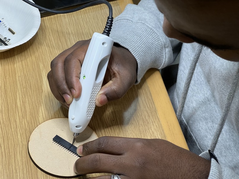
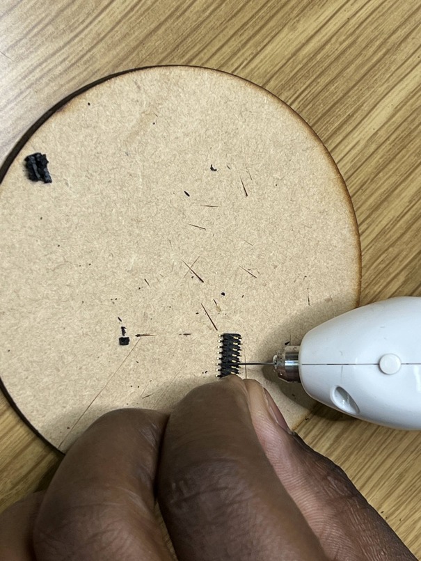
- Some components like headers that are longer than desired was shortened. i used the Ultrasonic cutter for that purpose
- After that, i began solderin them one by one. using the conventional soldering iron


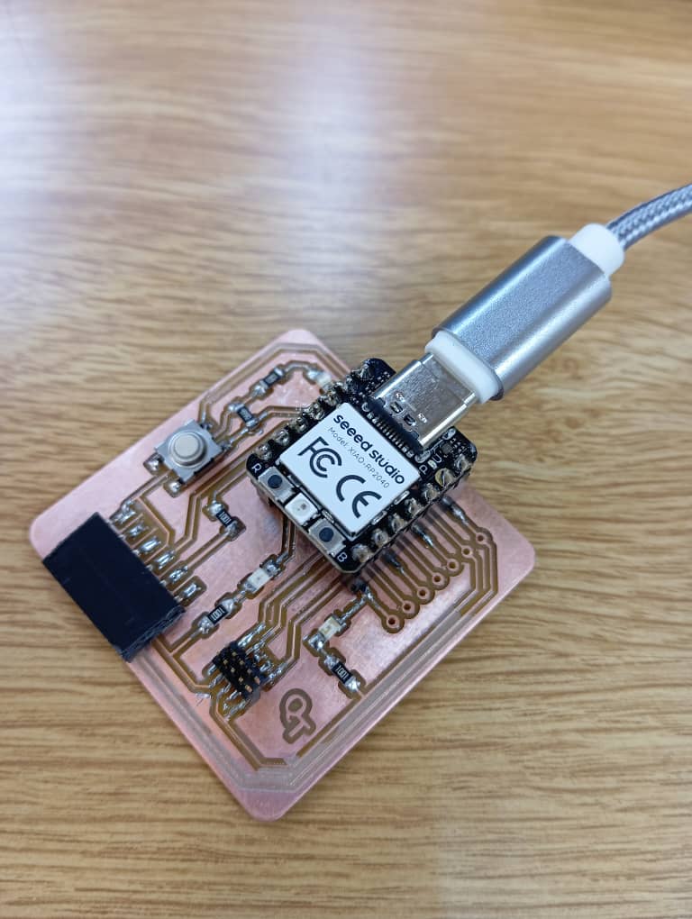
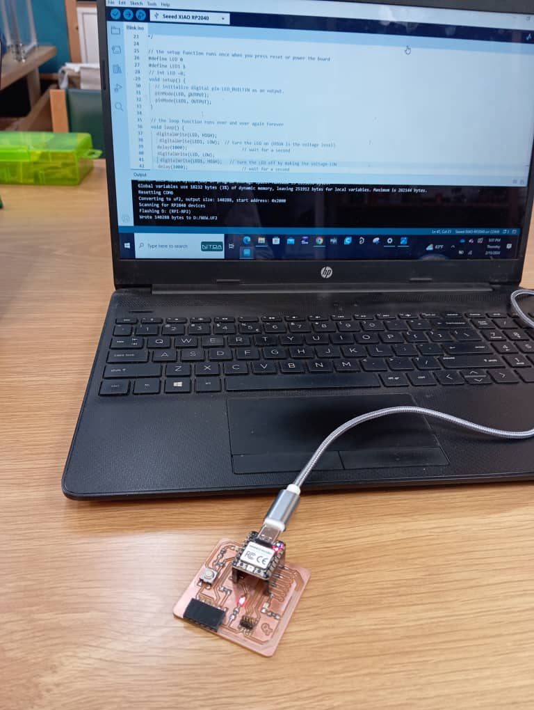
Testing
This is where the work pays or not, to test my board i did the following:
- I connected the xiao board to my system
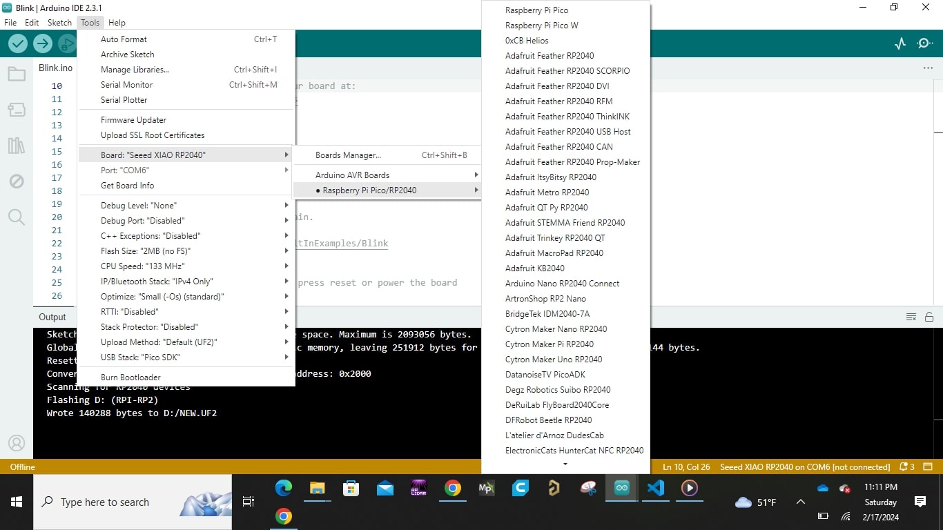
- I then launched the arduino IDE and click file, preference
- Then i added the url (https://github.com/earlephilhower/arduino-pico/releases/download/global/package_rp2040_index.json) under "additional board manager url field" under references according to the Quentorres referenced site
- I then selected port and chose the right serial port
- I then selected tools , board, raspberrypi pico/Rp2040, scroll down and selected seed Xiao RP2040
- I then uploaded blink from examples basic to test one of the led and it worked
Conclusion
To conclude, from results obtained it can be sai that electronic production with
milling machine
is a handy method when quick prototyping is required. As it has proven to be fast
for a prototype,
efficient and pretty standard.
I have learned immensely from this and i am really grateful for the experience, with
this i come to the
end of my week 4 documentation.
All source files can be found Here at the side bar.