

Input Devices
Input devices are often refer to as sensors. Sensors play a critical role in embedded systems by detecting and measuring physical phenomena, converting them into electrical signals that can be processed by the microcontroller.
Group Assignment
The Kannai team as usual was divided into two and i worked with Ahmad
Tijjani Ishaq
The task is to probe an input device’s analog levels and digital signals.
Our documentation can be found on
Our group assignment page
Individual Assignment
All source files can be found Here at the side bar.
Assignment for the week is to measure something: add a sensor to a microcontroller board that you have designed and read it
Introduction
Sensors are input devices used for reading various type of data and translating it into signals to be interpreted by the microcontroller
Some examples of Input devices are as follows:
- Temperature Sensor:
- Light sensor
- Proximity sensor
- humidity sensor
Keypad
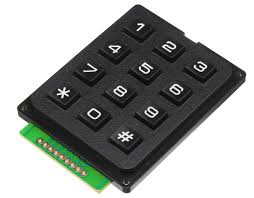
Keypads are frequently utilized in applications where user wish to input data whether numerical or alphabetical. it is part of interface devices
Interfacing keypad
I used my final project board 2 that i made in my Electronics design week. I connected the seven (7) pins of my keypad to pin gp6 through gp12 of the raspberry pi pico development board.
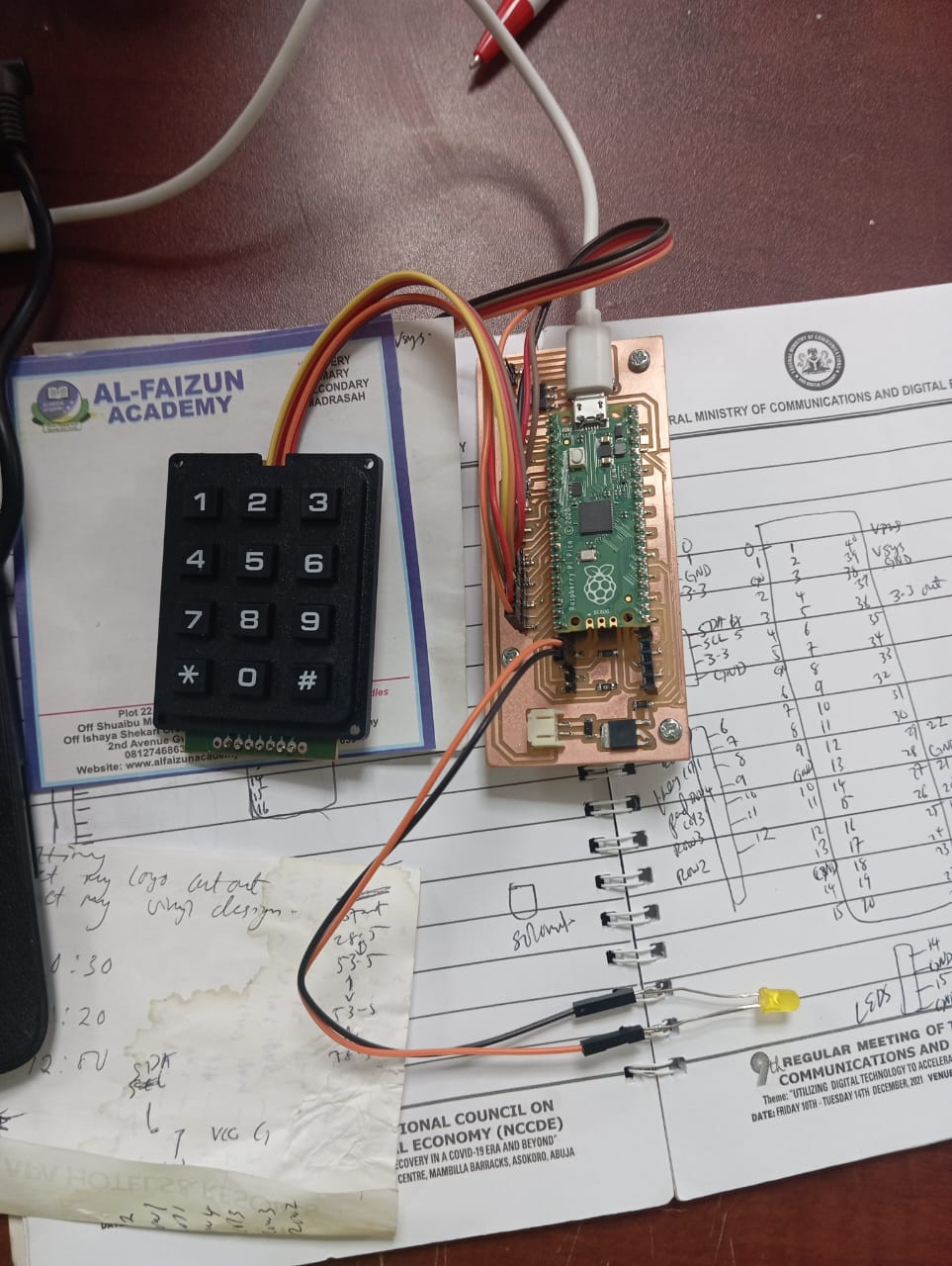
When using the generally used keypad.h library on my pico, the keypad module misbehaved and did not respond as it does when using the arduino boards so i decided to work with chat gpt and made my own custom keypad library. the code i used is Keypad code arduino and it contains the library.
fingerprint/thumbprint sensor
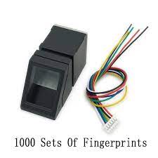
Thumbprint sensors, also known as fingerprint scanners or biometric sensors, are are used for capturing fingerprints data and can be used for security applications
Interfacing Thumbprint sensor
The sensor is serial based and uses the software serial library to communicate with the pico. It has six pins but i use four(4) pins/wires as follows:
- GND connected to ground of pico
- Vcc connected to 3.3v pin of my pico
- RX to TX(0) of pico
- TX to RX(1) of pico
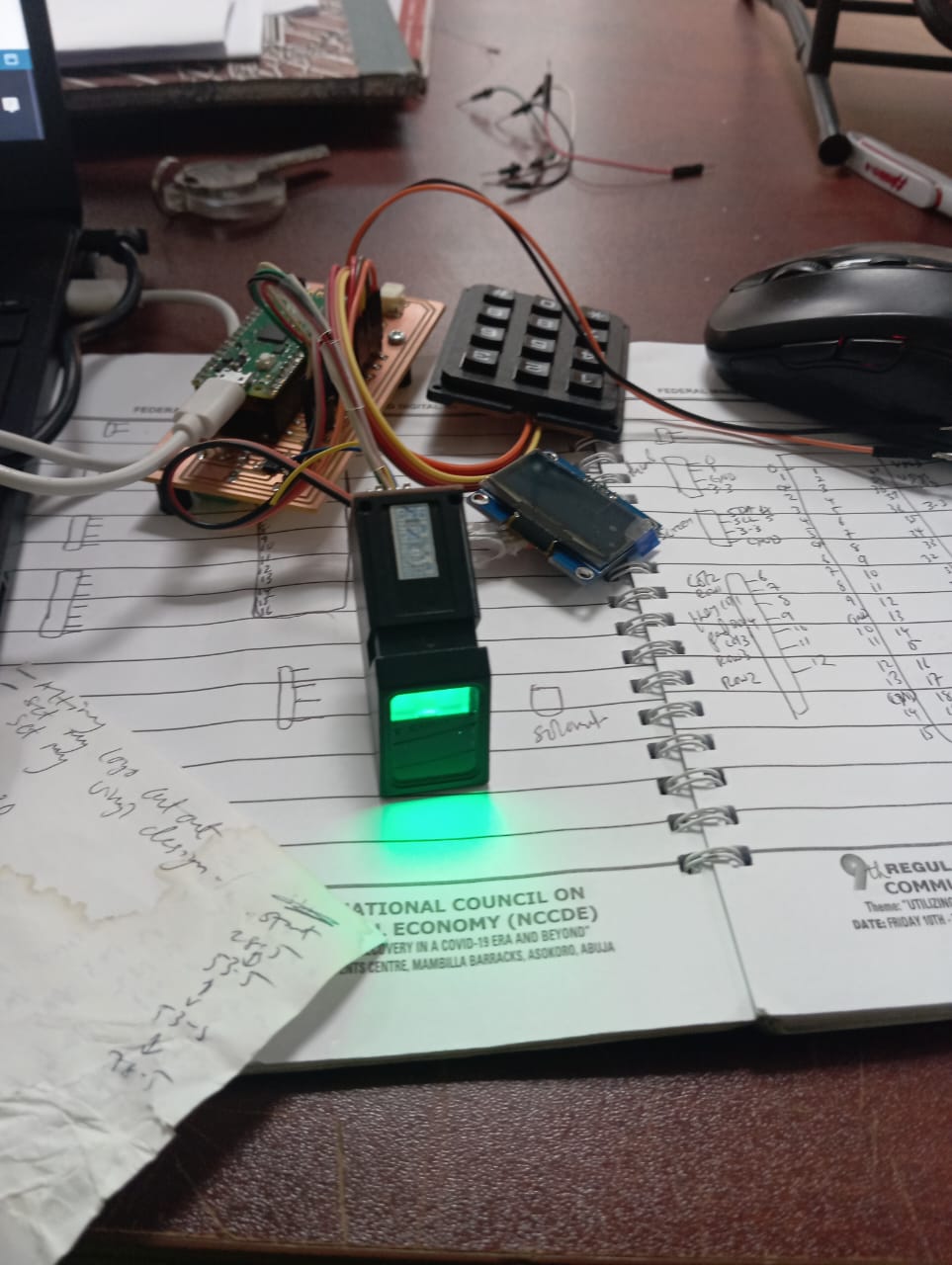
I uploaded Thumbprint code arduinoand it works well. I had an issue earlier on when designing my board, i found out that despite having so many serial pins on my pico only the default pins 0 and 1 works with the software serial library. I tried gp16 and gp17 but nothing worked and i had to stick to gp0 and gp1.
All source files can be found Here at the side bar.