

Output Devices
These are devices we used to translate signals into actions. we use them for running day to day activity and they get command from the controller
examples are:
- electrical motors such as DC motors, servors and stepper motors.
- Display devices such as LCD screens and Oled displays
- others such as LEDs and radio modules
Group Assignment
The Kannai team as usual was divided into two and i worked with Ahmad Tijjani Ishaq The task is to measure the power consumption of an output device. Our documentation can be found on Our group assignment page
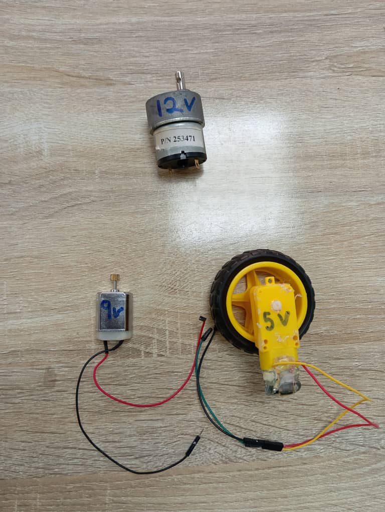
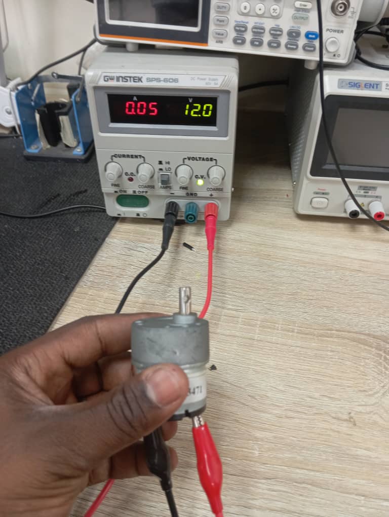
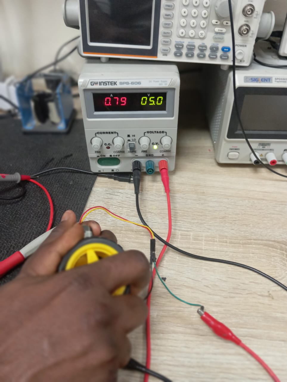
We measured power consumption of three different dc motors (12v, 9v, and 5v ), using a multimeter and also power supply. We measured power for stall possition too.
Individual Assignment
All source files can be found Here at the side bar.
Assignment for the week is to add an output device to a microcontroller board you’ve designed, and program it to do something
I designed and Produced my final Project electronic board and more about it can be found on my week 8 Assignment page.
On my board, there are pins for output devices such as:
- Solonoid
- LED And more spaces are also provided. I focused on The solonoid aspect for my assignment and i also played with :
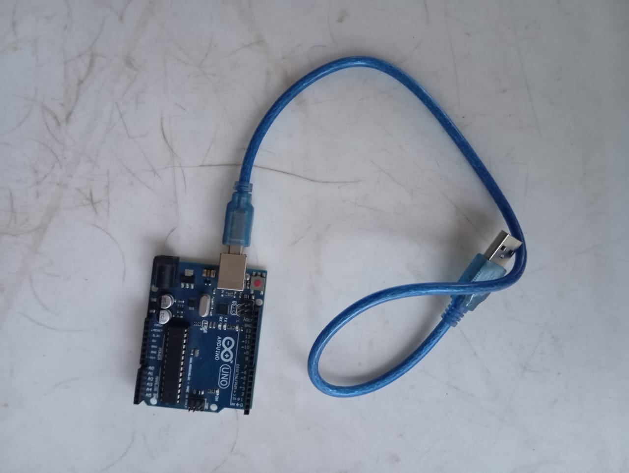
- DC motor (control with relay and arduino uno board)
- Servo motor with arduino uno board
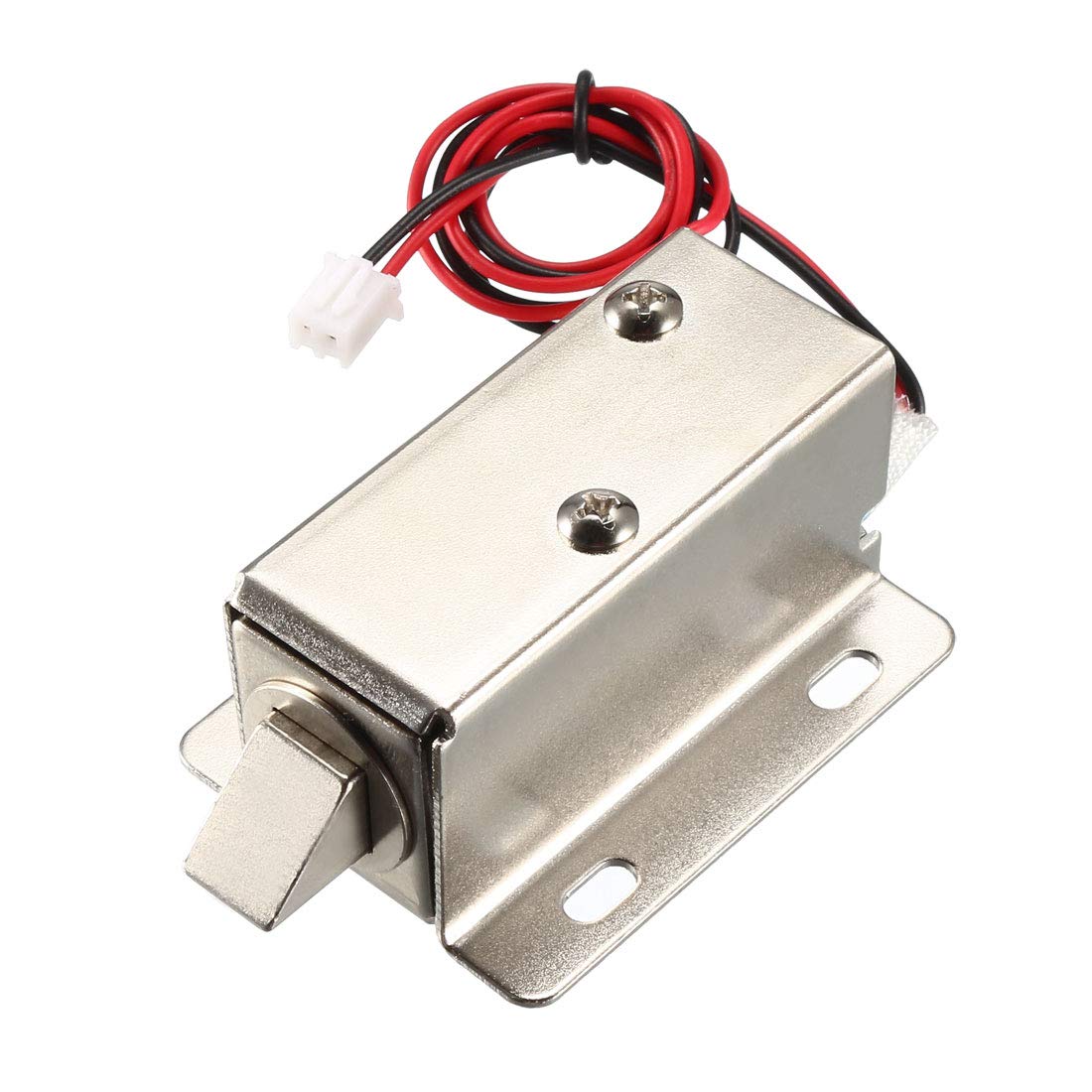
Solonoid Lock
A solenoid lock is a type of electromechanical locking mechanism that extend or retracts its tip when excited with electrical signal. This makes it suitable for my final project.
Based on the working principle, a simple High and Low code can extend or contract the solonoid plunger But one
problem arises. I am using a 12v solonoid device and the output signals of my pico is 3.3v.
To solve this i had to make a seperate power system of 12v on my board and also provide a switching mechanism.
There are many ways to perform switching operation for example we can use a relay or a transistor. I chose a transistor for that purpose.
Switching System
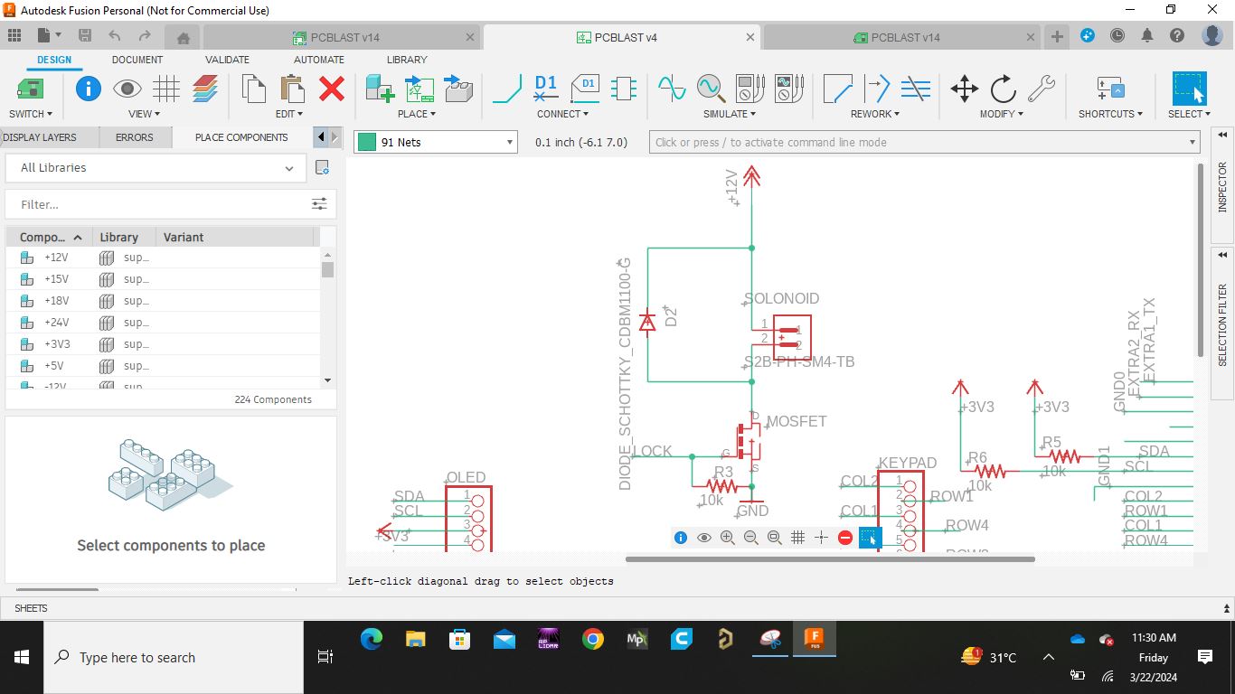
I designed my switching system with a mosfet transistor as follows:
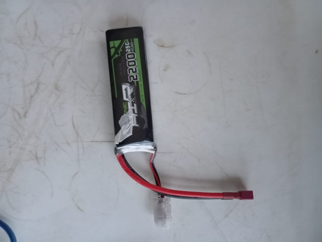
- I used a 3s battery to provide the required 12v for the solonoid
- I connected the gate of the mosfet to the signal pin of my pico
- I connected the source to ground
- then i connected the drain to one of the pin of my solonoid
- The other pin of the solonoid was connected to the 12v + of my battery
- Once there is signal at the gate, the mosfet switches on the solonoid
- The diagram is as shown below
I used a basic blink code to test the working of my solonoid
I completed my activity and decided to work with DC motor and servo motor using arduino board as follows.
DC Motor
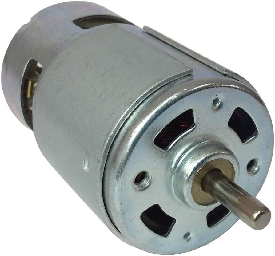
A DC motor operates based on the principles of electromagnetism and the Lorentz force law.
Wiring
The wiring is simple as the DC motor has just two pins. One is connected to the signal pin and the other to ground,
once the signal pin is set to high it turns on the DC motor. However, The voltage level at the pins of arduino uno
is 5v which is not enough for my 12v DC motor hence i resort to using relay for switching purpose.
Relay
A relay is an electromechanical device used for switching between two voltage values. it is used for switching purposes. relays play a crucial role in controlling electrical circuits in various applications, providing isolation, protection, and switching capabilities. I used the 12v electromechanical relay for the switching purpose.
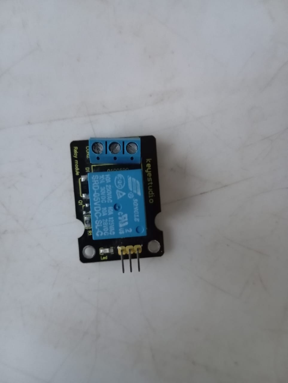
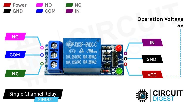
As seen in the above pictures, I used key yes studio relay and i connected my motor as follows:
- I connected the IN to the signal pin
- I connected the GND to gnd of arduino
- I connected the VCC to 5v arduino
- I connected the NO to one pin of the DC motor
- I connected the COM to the possitive voltage of my 12v battery
- I connected the negative of my battery to the other pin of my DC motor
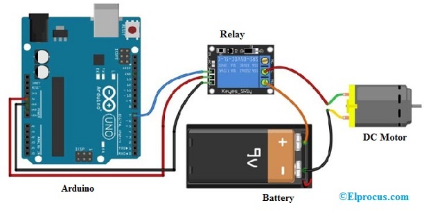
- Below is a similar circuit using 9v battery
Servo motor
A servo motor is a an actuator that allows for precise control of position. It is used in various applications such as robotics, automation, remote-controlled vehicles, and precision engineering where accurate and smooth motion control is required. servo motors provide precise motion control and are essential components in various electromechanical systems and applications. I used the tower pro servo motor with arduino uno

Wiring
The servo motor as seen in picture above has 3 pins, Then red is connected to 5v of arduino,
the brown is connected to ground and the yellow/orange is connected to the signal pin.
I uploaded two codes, the first is the sweep code from the servo library example and the second
code is a custome sketch to move the servo to different angles as shown below.
Oled Display
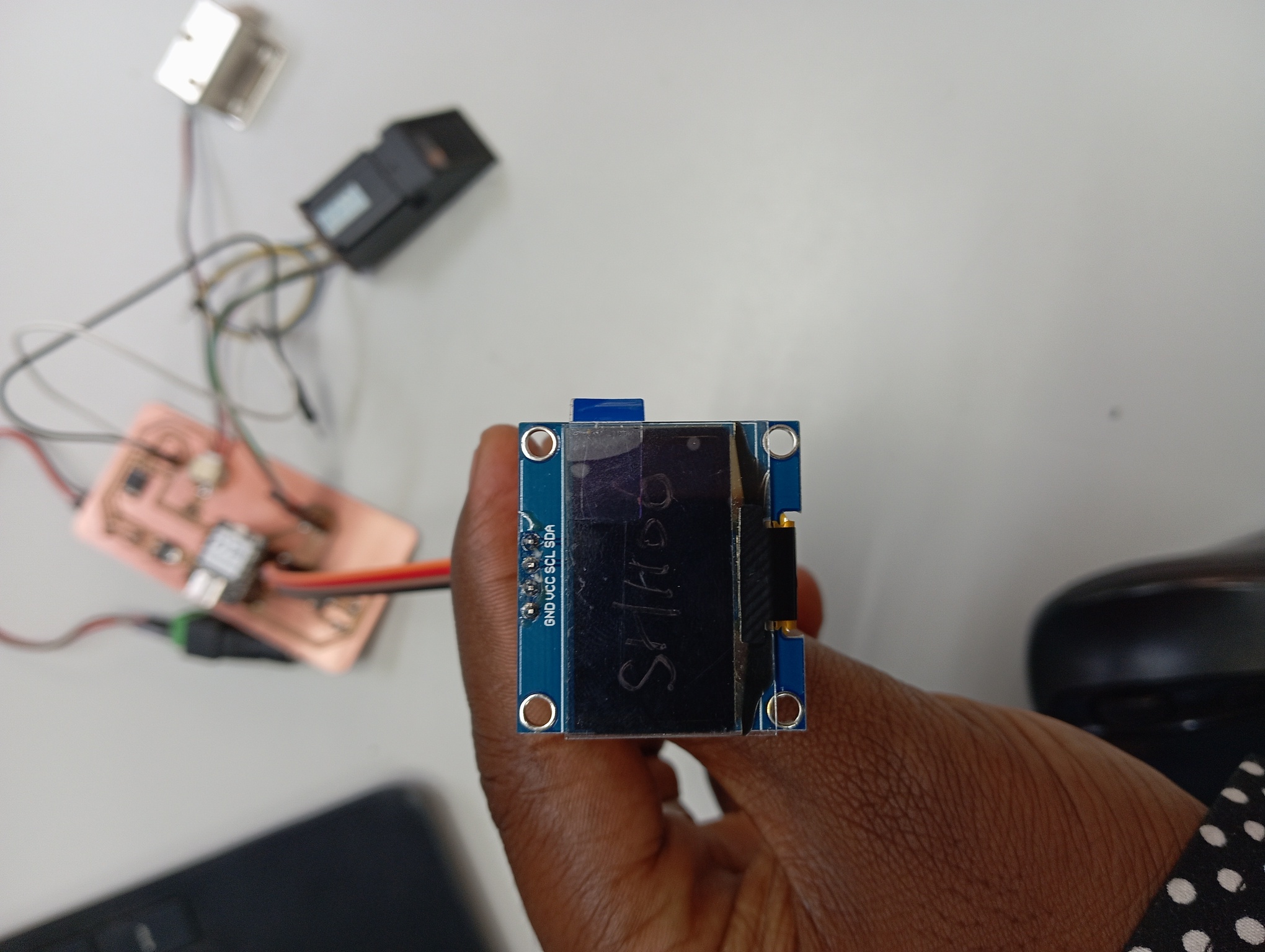
There are many kinds of display suitable and used for showing data to a user (interface) such as LCD, Oled and even serial monitor. Here i will discuss the SSH1106 oled display because it typically offers low power consumption, high contrast, and is suitable for my project. It has simple design and is easy to use for display.
In this section, i will explain how it works and the basic code needed to get it to work. as for practical use it is explained in my networking week because it uses i2c network protocol which is part of the activity of that week.
Pinout
The SSH1106 has four pins which can be connected for example to a xiao rp2040 as follows.
- GND connected to the GND pin of my project board
- VCC connected to The 3.3v of my project board
- SCL connected to SCL pin of my xiao rp2040
- SDA connected to SDA pin of my xiao rp2040
// Include section where the necessary libraries are called
#include
#include
#include
#include

//Defining The address of the i2c for initialization
#define i2c_Address 0x3c

//Defining the size of the oled as there are different versions
#define SCREEN_WIDTH 128 // OLED display width, in pixels
#define SCREEN_HEIGHT 64 // OLED display height, in pixels
#define OLED_RESET -1   //   QT-PY / XIAO
Adafruit_SH1106G display = Adafruit_SH1106G(SCREEN_WIDTH, SCREEN_HEIGHT, &Wire, OLED_RESET);


//setting up the system
void setup() {
Serial.begin(9600);
delay(250); // wait for the OLED to power up
display.begin(i2c_Address, true); // Address 0x3C default
display.display();
delay(2000);
}


//beginning the loop where  the below sentences would be written continuously
void loop() {
display.clearDisplay(); //This clear the screen
display.setTextSize(1); //This set the font size
display.setTextColor(SH110X_WHITE); //this is for font color
display.setCursor(0, 0); //this places the cursor at the first pixel available though it can be changed
display.println("Hey There. Its Fab academy"); //this prints the sentence on the screen
display.display(); // this displays the printed sentence

display.clearDisplay();
display.setTextSize(1);
display.setTextColor(SH110X_WHITE);
display.setCursor(0, 0);
display.println("Its Electrifying");
display.display();

}
As seen above, the function of all the block sections in the code is explained . but notably, before we run this we need to run the i2c scanner on the oled to identify the address to be used. this code for that is given below
#include <Wire.h>

void setup() {
    Wire.begin();

    Serial.begin(9600);
    while (!Serial);             // Leonardo: wait for serial monitor
    Serial.println("\nI2C Scanner");
}

void loop() {
    byte error, address;
    int nDevices;

    Serial.println("Scanning...");

    nDevices = 0;
    for(address = 1; address < 127; address++ ) {
    // The i2c_scanner uses the return value of
    // the Write.endTransmission to see if
    // a device did acknowledge to the address.
    Wire.beginTransmission(address);
    error = Wire.endTransmission();

    if (error == 0) {
        Serial.print("I2C device found at address 0x");
        if (address < 16)
        Serial.print("0");
        Serial.print(address, HEX);
        Serial.println("  !");

        nDevices++;
    } else if (error == 4) {
        Serial.print("Unknown error at address 0x");
        if (address < 16)
        Serial.print("0");
        Serial.println(address, HEX);
    }
    }
    if (nDevices == 0)
    Serial.println("No I2C devices found\n");
    else
    Serial.println("done\n");

    delay(5000); // wait 5 seconds for next scan
}
After obtaining the address one can run the first code to test the functionality of the device.
I used the oled as part of my final project to display the following sentences:
- my logo Touchguard and welcome
                                            testdrawbitmap();
                                            delay(3000);
                                            display.clearDisplay();
                                            display.setTextSize(2);
                                            display.setTextColor(SH110X_WHITE);
                                            display.setCursor(4, 4);
                                            display.println("Welcome");
                                            display.display();
                                            void testdrawbitmap(void) {
                                                display.clearDisplay();

                                                display.drawBitmap(
                                                  (display.width() - LOGO_WIDTH) / 2,
                                                  (display.height() - LOGO_HEIGHT) / 2,
                                                  logo16_glcd_bmp, LOGO_WIDTH, LOGO_HEIGHT, 1);
                                                display.display();
                                              }
                                            display.clearDisplay();
                                            display.setTextSize(1);
                                            display.setTextColor(SH110X_WHITE);
                                            display.setCursor(0, 0);
                                            display.println("Enter your pass word");
                                            display.println("or");
                                            display.println("scan your finger");

                                            display.display();
                                            display.clearDisplay();
                                            display.setTextSize(2);
                                            display.setTextColor(SH110X_WHITE);
                                            display.setCursor(4, 4);
                                            display.println("Correct");
                                            display.println(" Welcome");
                                            display.display();
As for printing my logo on the screen, that is one of the activity i did in my networking week . Source code for final project can be found in the final project week
All source files can be found Here at the side bar.