7. Computer-controlled machining
This is the documentation of week 7 activity Computer-Controlled Machining by Ahmad Tijjani Ishaq and Muhammad Jidda.
This weeks activity focusses on the use of Large CNC machines for cutting and engraving on materials mainly wood.
As for our individual Assignment it can be found here Jidda and Ahmed
The group task for this weeks activity are:
  - Do your lab’s safety training;
  - Test runout, alignment, fixturing, speeds, feeds, materials, and toolpaths for your machine
Control Machining
Controlled machining refers to the precise and regulated process of shaping or cutting materials using machinery with a high level of automation and precision. This process is commonly employed in various industries, including manufacturing, aerospace, automotive, and electronics, among others. The primary objective of controlled machining is to achieve accurate and repeatable results in the production of components and parts.
machine
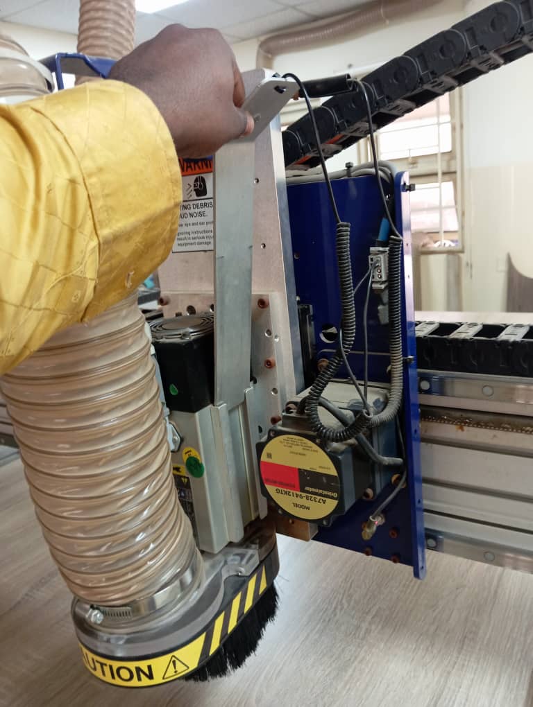
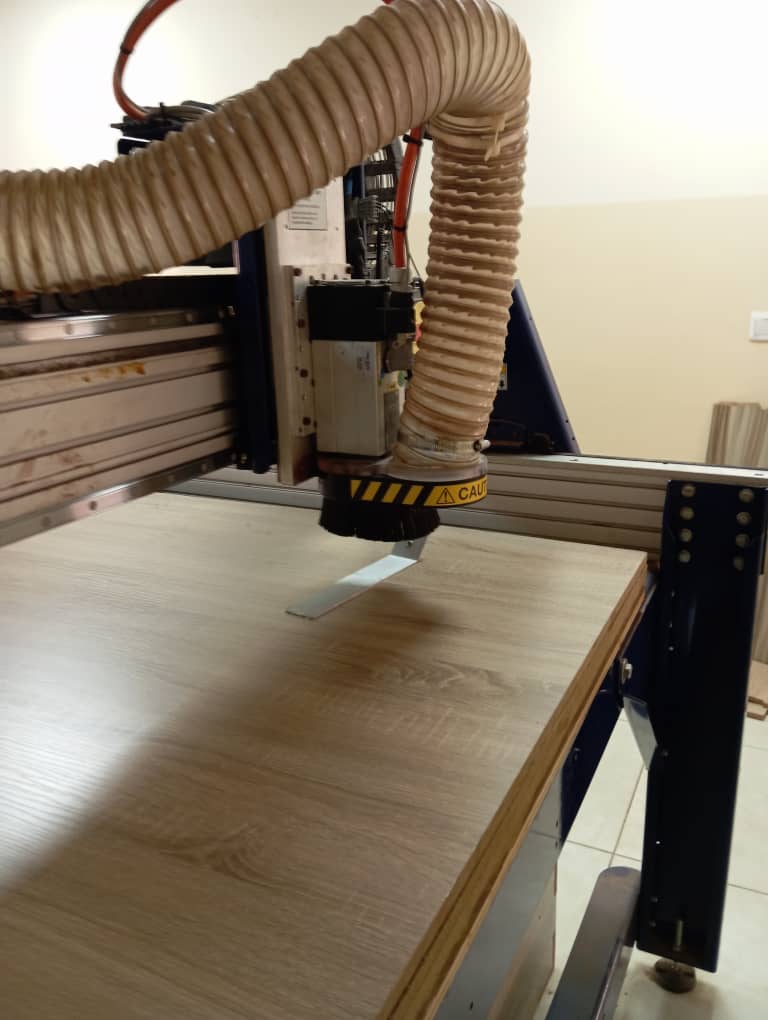
We work with shopbot3 CNC machine for our controlled machinning activity.
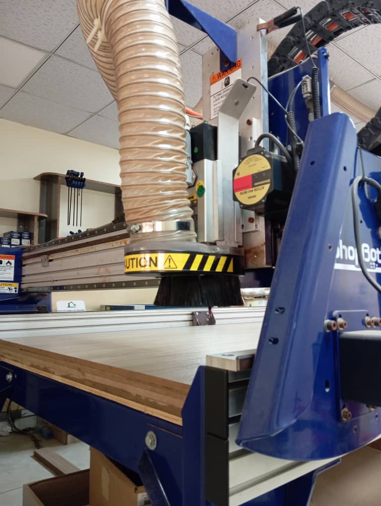
software
- fusion 360 for 3D design, modelling and assembly.
- Shaper tools plugin for exporting of faces.
- Corel draw for exporting as pdf.
- Aspire for gcode and tool path generation.
- Shopbot3 for operating the shopbot machine.
Safety Training.
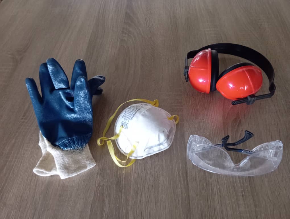
For safety purposes we were given safety wears as well as safety tips in the lab. The wears are as follows:
- Gloves
- Eye glasses
- Nose cover
- Ear cover
- Fire estinguisher
Before we commenced operation, our instructor gave us some safety tips so as to prevent accidents or injuries some of which are:
- Always stay around the machine when in operation.
- Be vigilant, keep your your cursor on the stop button of the Shopbot software.
- There is an emergency stop button, always be ready to hit when a problem is observed.
- Keep workpiece surface free from dust/wood particles as much as possible to prevent fire gushing due to friction.
Tools
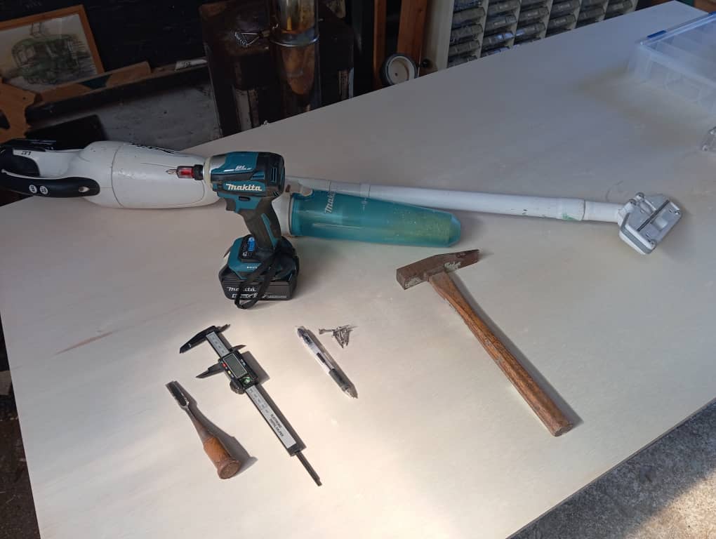
we were introduced to the tools that we will use in the process, tools such as
- mallet
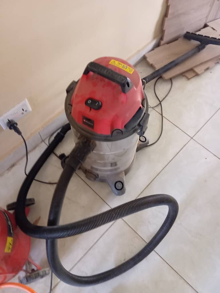
- Vacuum cleaner
- measurement ruler
- vanier calliper
- marker
- Hand drilling machine
- Hammmer
- chissle
Alignment
Alignment test is done to ensure that our machine makes straight cut so as to enable all parts fix properly.
Some times, the tool head of the machine can have misalignment and hence end up making bigger toolpath than expected and causing reduction in the size of the path cut.
To test for Alignment, we made a simple cube design of width = height= 100mm.
To cut this, we used the following;
- Material (wood)
- Thickness (16mm)
- Machine (shopbot)
- Tool diameter (6mm)
We follow the following processes to achive our cutting:
- we started by first designing on Aspire since its not a complex design that requires a c more complex cad software.
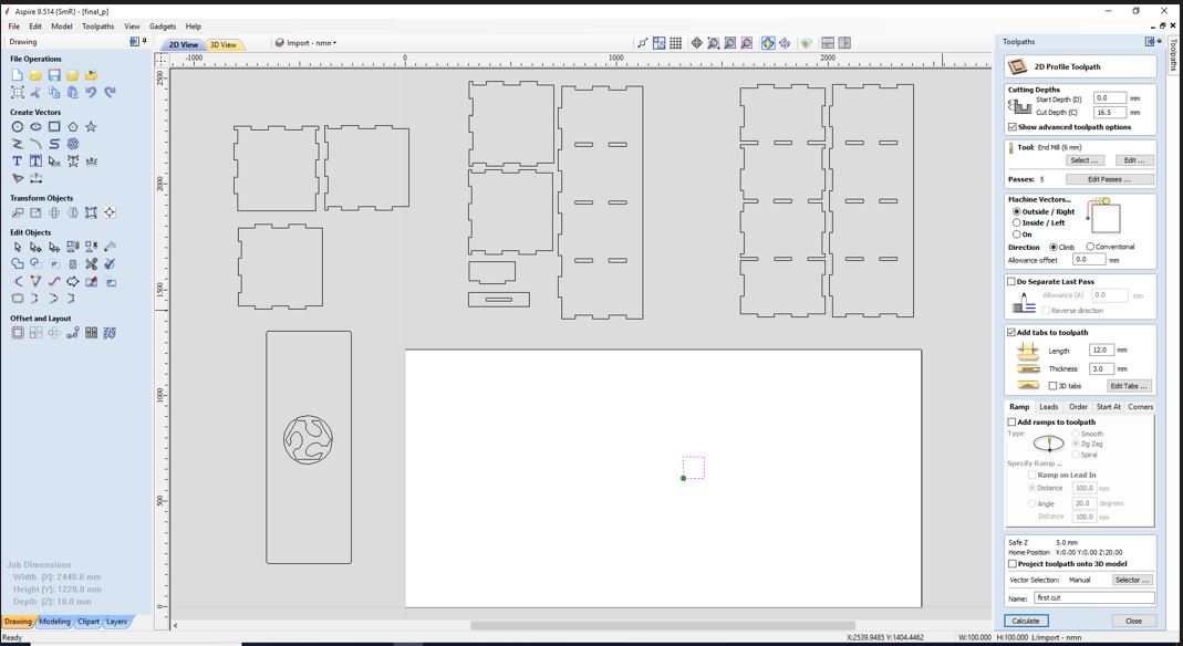
- then We generated the tool path by clicking tool path at the top right corner. A window then opens up,
We have different choice for different tool path types. We selected the profile type
we inserted the following .
- Cut depth 0.00 to 16.5 (we added .5 because we want the tool to cut through)
- Passes 4
- Add tabs. We added two tabs
- Pattern outside right so that we can get the exact size we wanted
- After that we then generated the tool by selecting the calculate tab. With that cutting pattern is generated and we then saved the gcode.
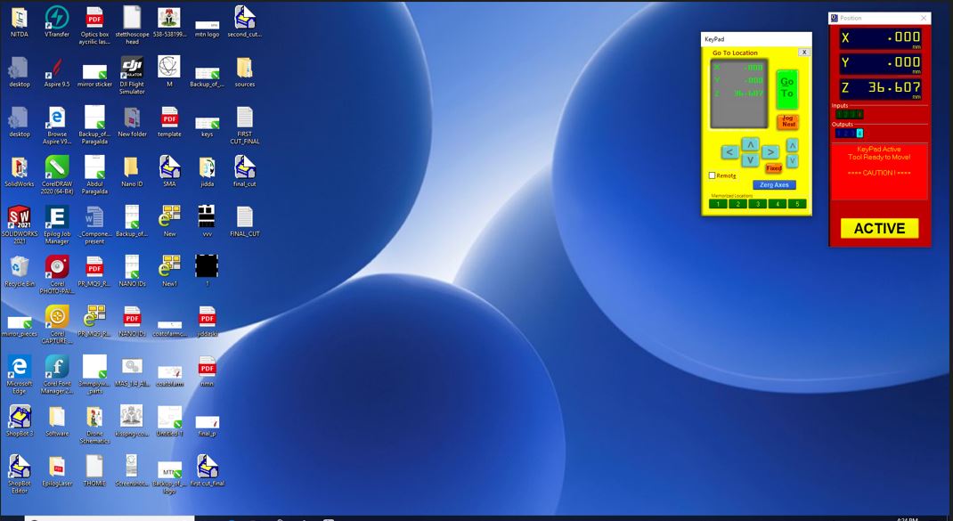
- Next we launch the shopbot3 app and switched on the machine.
- On the shopbot app we clicked the xy zero and the machine automatically zeroed it’s axis taking advantage of the limiting switch it has.
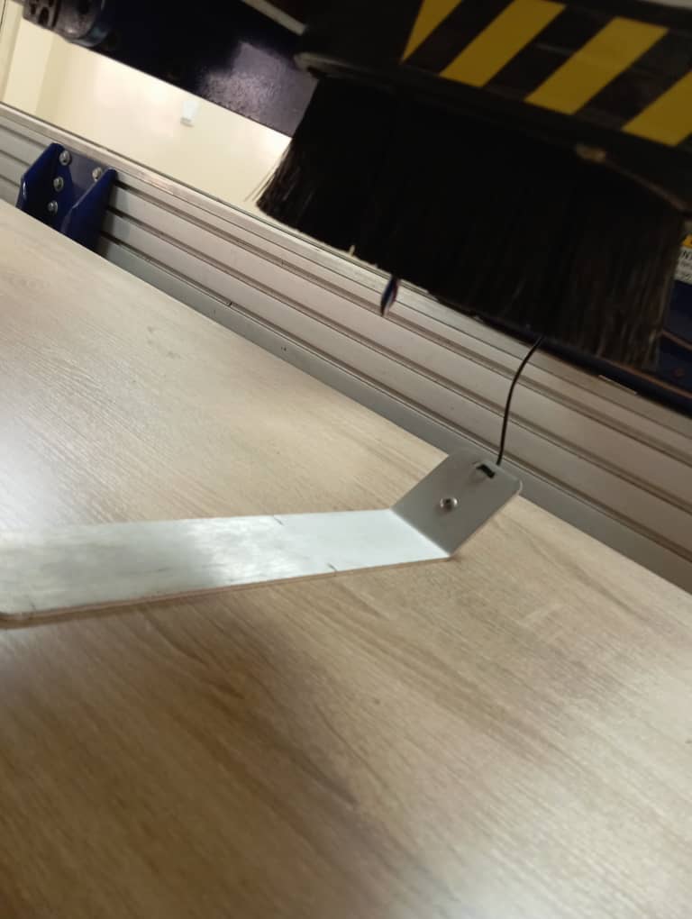
- Then the machine have a manual control section, we used it to move the head to a suitable flat position on the work material surface ready for z axis zero. We clicked on the z axis function and it prompted us to place the z axis plate directly under the tool bit. which we did so and then it automatically did the z axis zeroing.
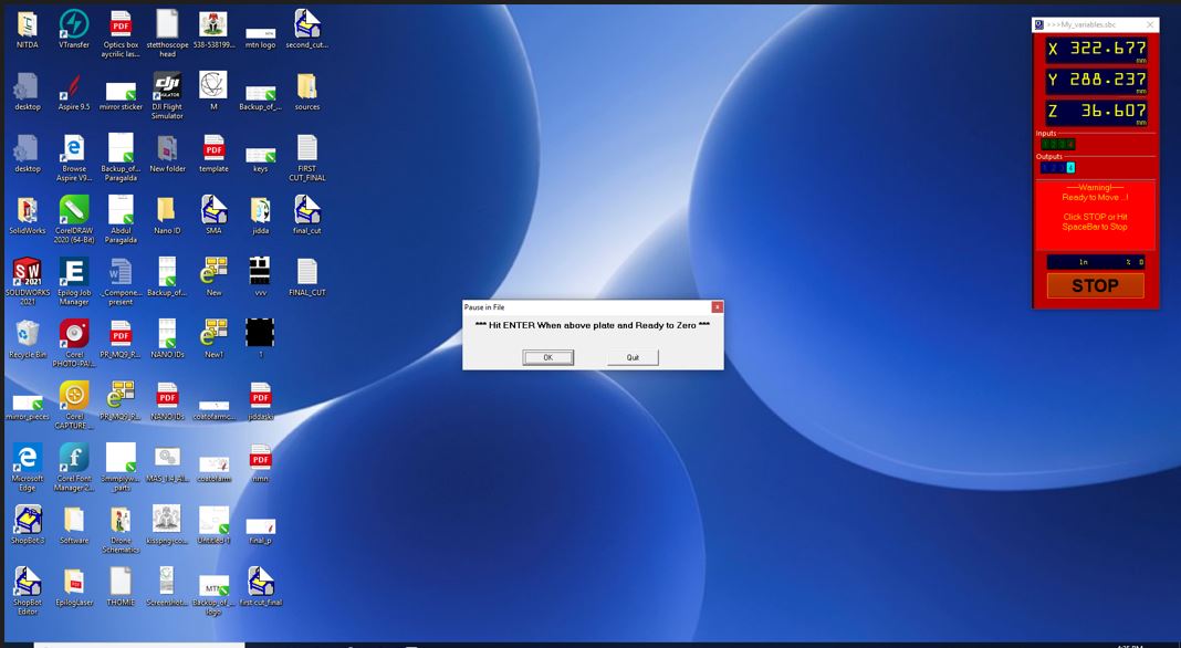
- After completion of z axis we then select cut part and proceed to cut our work piece.
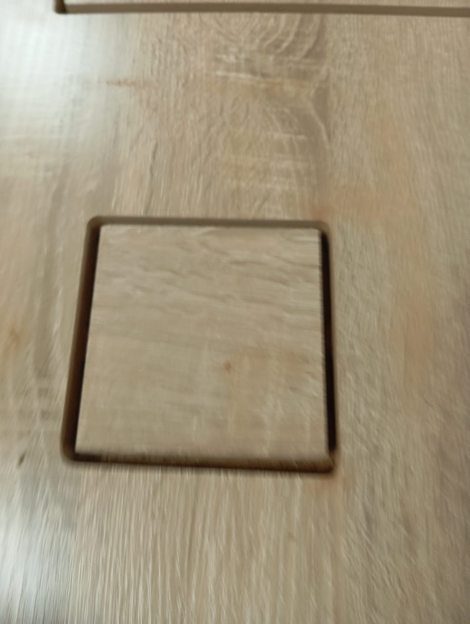
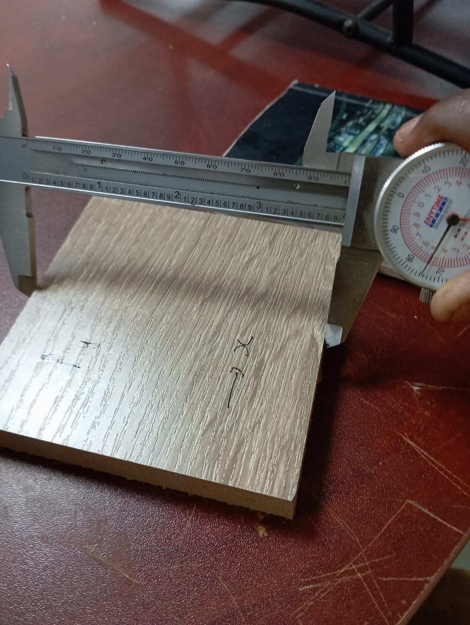
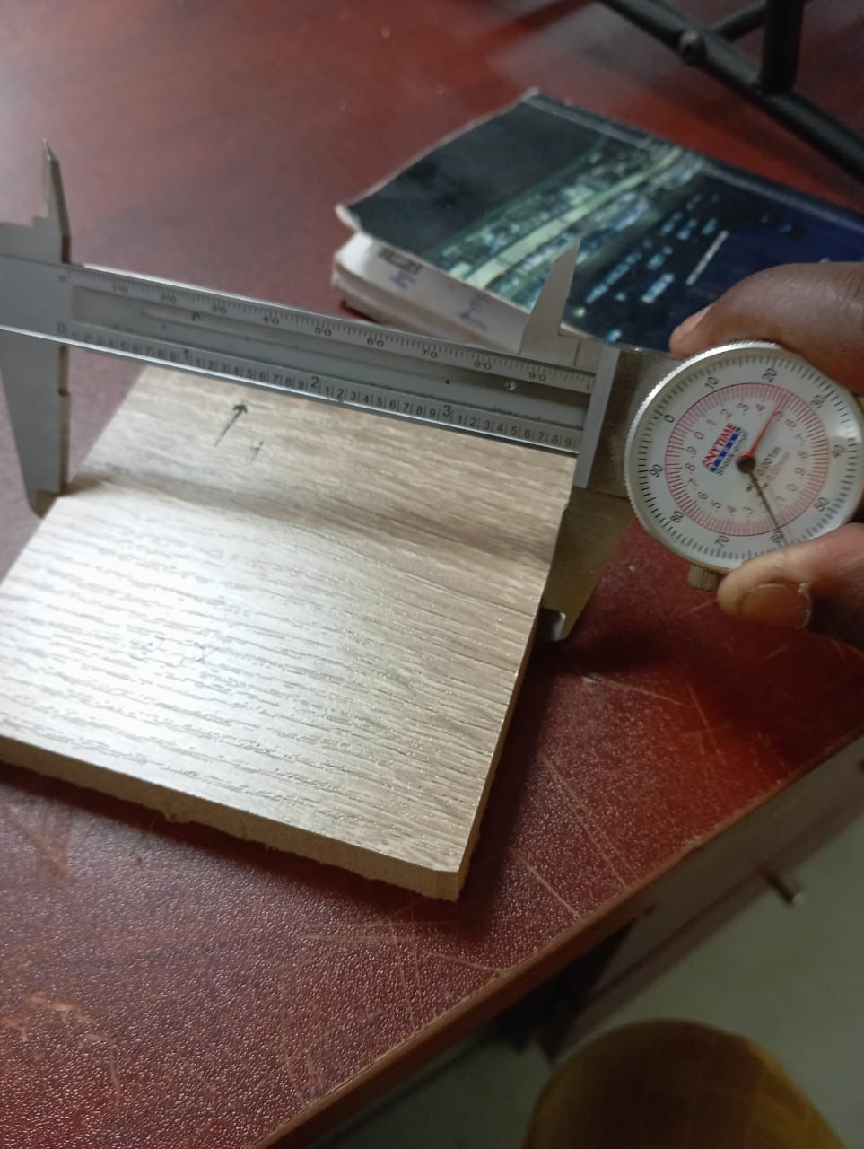
- Upon completion we used chissle to break out the tabs and then made measurement on our cut out. Both x and y shows 100mm +-0.1
 {:width=”400px”}
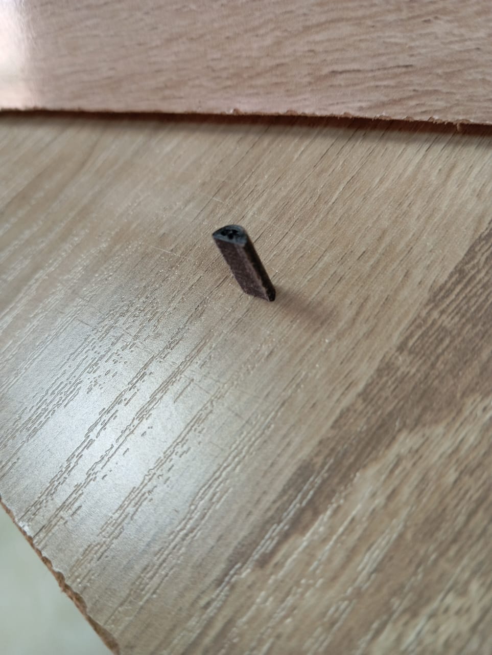
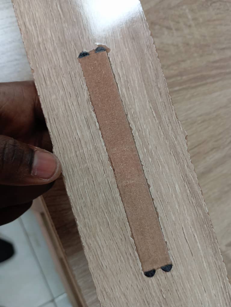
Fixturing
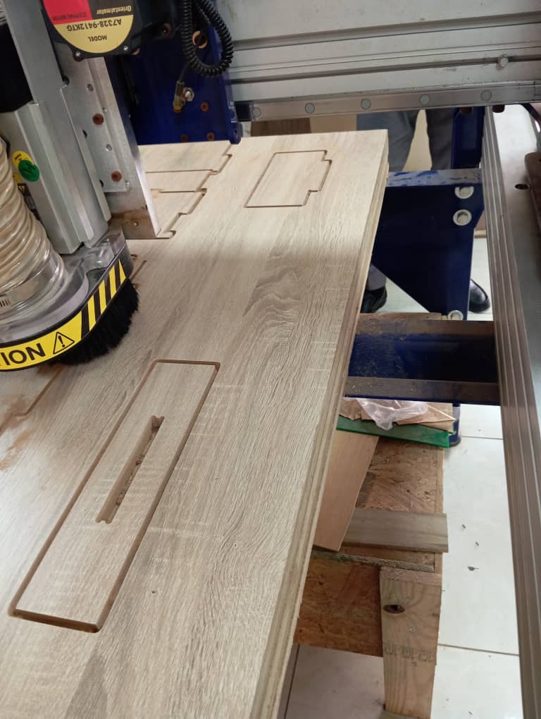
The fitting/fixturing test is done to see how firm and successful work pieces can be meshed together. We made a simple design as shown below to achieve that. - We started by designing on fusion 360 . - Then we exported the faces as SVG using shaper tools


- The SVG file was then opened in Corel draw, black fill was removed and the file exported as pdf . We try so many extensions but Corel draw exports as pdf or BMP only.
- We imported the files into the aspire software and repeated similar process as was done in alignment test.
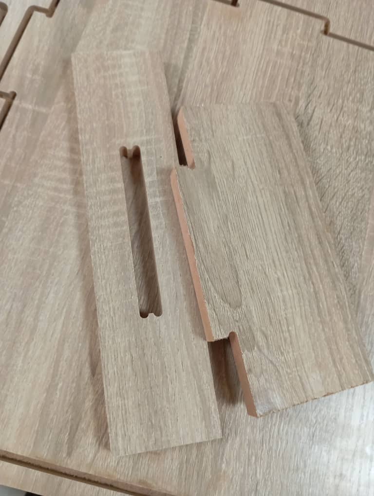
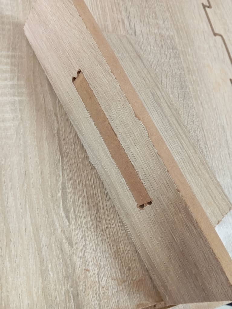
Note:
we used tbone in our design hence we had slightly big holes exposed so we decided to make 3D prints and covered it up. -The two piece fits perfectly and that marks the end of our group project
Source Files
Download pdf files of parts cut
Download Svg file 1 for fixturing
Download Svg file 2 for fixturing
Download aspire file used in generating cutting pattern/g-codes