3. Computer-controlled cutting
Group Assignment Overview
This is the group assignment of the week. We understood that this was an exercise to understand the characteristics of the laser-cutter we are going to use at our local lab. We tested the Universal VLS Desktop VLS2.30:
Characterize your lasercutter’s focus, power, speed, rate, kerf, joint clearance and types.
There are four Fab Academy students in our lab, two from Nigeria and two from Japan. And the one from Nigeria has not been physically present at the lab and the other also has been taking the local session separately. Due to the conflict of our schedules, our instructor has decided to divide us into two sub-groups for this week’s group assignment.
Group 1 (Ito-Yamada)
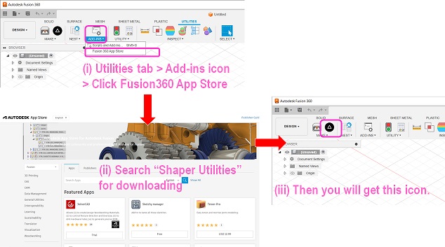
1. Preparation - Installation of Fusion360 Add-in “Shaper Utilities”
We first installed Shaper Utilities tool into Fusion360 on each of our laptops. Shaper Utilities could be used to read the 2D images from 3D shapes and get the vector data for laser-cutting.
2. Data and Test Cut
The data for these exercises were prepared in advance and given to us. For testing the cutting results with different power, speed and PPI (pulses per inch) parameters, we used the following diagram prepared in terms of CDR file. The reason we use the CDR file was that we use CorelDRAW to import 2D data for laser-cutting at FabLab Kannai.
Also, for this assignment for getting the best combination of parameters, we used the 5mm cardboard and the 2D data in terms of CDR file: CDR
2-1. Laser Power, Speed and PPI
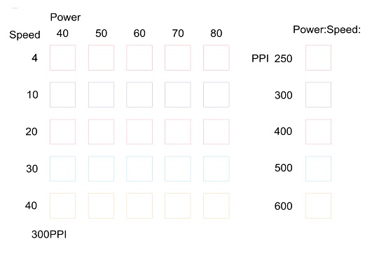
According to the UCP (Universal Control Panel) of the machine, five color parameters could be used for testing different parameters for vector data. Therefore, we first fixed the value of the PPI as 300, and tried different combinations of laser power and speed. For parameter setting on the UCP, Koji’s individual assignment report for Week 3 may also be useful.
(3) Setting Parameters: Click the setting button on the UCP and then a new window will be popped up. First, click the “Material Database” tab and choose the material type and thickness. Second, click the “Manual Control” tab and set the parameters (Power, Speed, PPI (pulse per inch), and Z-axis) for each of the colors to be used. You have to finish the parameter setting for every color by cliking “Set” button. PPI means how many laser pulses per inch are used for the engraving.
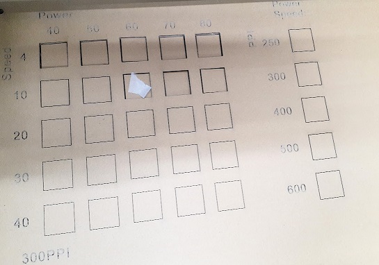
Please note that for cutting, we have to color all the outlines red, not various colors as shown in the attached figure.

The above snapshot shows the result: When PPI is set as 300, we can bet the best result with the speed as 10 and the power as 60 or 70. If the speed is slower than this or the power is stronger than these, the kerf will be too wide and the cutouts will be easily removed out of the board.
Secondly, with the speed and power fixed as 10 and 60 respectively, we tried to change the PPI parameter from 250 to 600. The snapshot attached below is the test result. It seemed that the PPI should be either 250 or 300 but we couldn’t conclude which one should be better. Or perhaps we should stay with PPI 300.
To conclude, we deceded to proceed with the following combination of the parameters:
Power: 10 / Speed: 60 / PPI: 300
2-2. Focus
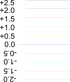
The cut result may be affected by the laser focus, a distance between the laser and the material. If it is best-focused and the laser beam is concentrated on to the target point more clear and precisely, it could cut it with the minimum kerf width, no burning. First we manually set the focus in terms of the laser-head distance along the Z-axis. After drawing the first straight line with a set of parameters for power, speed and PPI as we got at 2-1 above, we shifted the straight line by every 0.5mm and drew another straight lines. We repeated this sequence by shifting the straight line by every 0.5mm more than 4 to 5 times both upward and downward.
We hereby attach the sample image designed with CorelDRAW in terms of CDR file. The sample lines in the attached image were drawn in parallel horizontally. However, when we used the cardboard for this test, the test result might be affected by the waves sandwiched by the two cover sheets. If the lines are layed in parallel to the waves, the test result might not be so accurate. In order to test-cut all the lines under the same conditions, we decided to rotate the straight lines by 90 degrees.
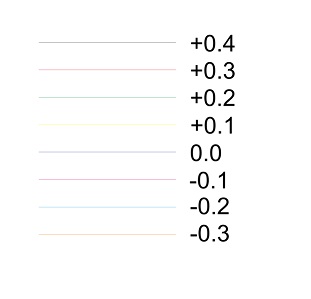
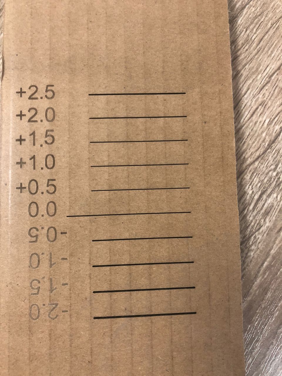
We set the Z-axis 3.7mm as zero point. After the first laser-cut, we shifted the line both downward (3.2mm, 2.7mm, 2.2mm, 1.7mm, 1.2mm) and upward (4.2mm, 4.7mm, 5.2mm, 5.7mm 6.2mm) one after another. Here is the snapshot of the test result.
It seemed that if the laser head was closer to the material, kerfs became wider. But if the distance was longer than 3.7mm, kerfs seemed to be remaining the same. With this result, we concluded that we would go with 3.7mm.
Z-axis: 3.7mm
2-3. Kerf Calculation
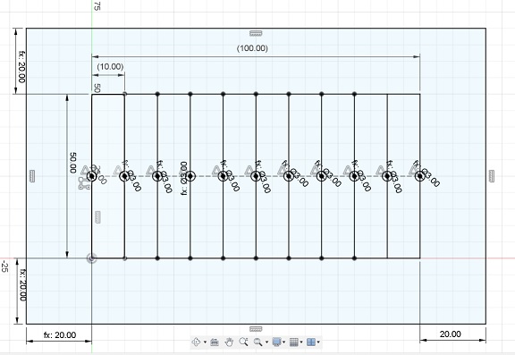
Now that we had the best combination of the settings of the laser-cutter, we had to calculate the kerf width with the best conditions of our laser-cutter. For this practice, we prepared the following sketch on Fusion360.
Laser Kerf Data: F3D
There are 10 rectangles with 10mm width and 50mm height. With those 10 rectangle combined, the total width is 100mm.
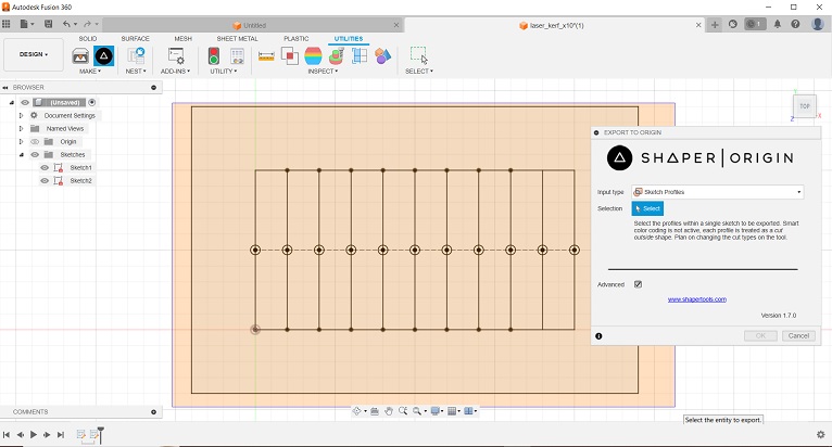
Then, using the Shaper Utilities dialogue on Fusion360, we selected “Sketch Profile” for input type, and then dragged the profiles on the workplain. Once we clicked “OK”, then we could automatically create cut data in terms of SVG file.
Then we moved to the laptop for laser-cutting, imported the SVG file to CorelDRAW and got ready for laser-cutting. Here are the result:
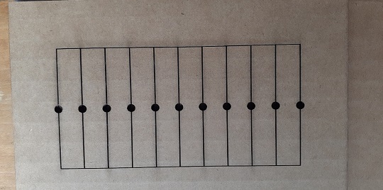
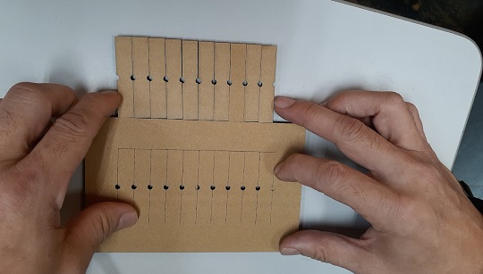
After the cutting, we placed those cutouts side-by-side and measured the total width.
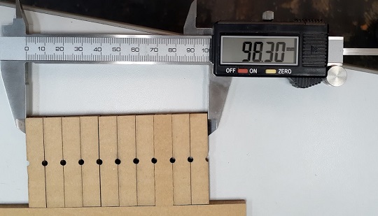
The total width of the 10 rectangles was 98.3mm, which means that 1.7mm (100mm-98.3mm) was burnt and lostby the laser. There were 10 full kerfs (9 full kerfs + 2 half kerfs) . Therefore, we can calculate the kerf width by dividing 1.7mm by 10 and conclude that under the current conditions, we had better take this into consideration:
Kerf: 0.17mm
2-4. Finger Joint Clearance
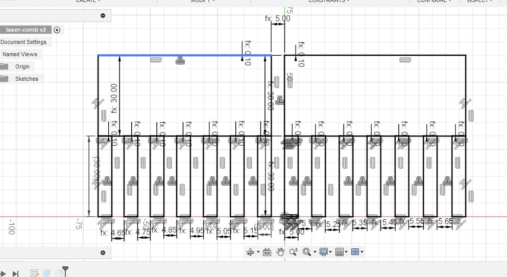
Now that we got the kerf of 0.17mm, we tried to integrate this parameter to the design of finger joints which could perfectly fit to each other without super glue. Kerf should be offset from the original outline of the sketch profile. For this practice, we prepared the following 2D design of the two combs.
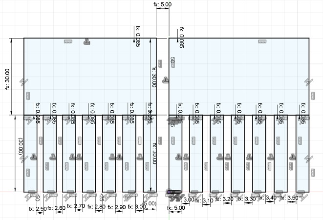
Comb Data: F3D
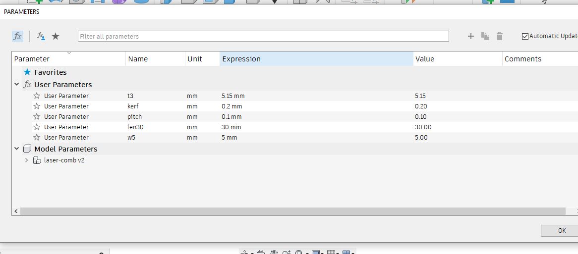
If you look at the dimensions of the sketch, you will see lots of numbers with “fx” in front. We defined our own parameters in the “Change Parameters” dialogue under the “Modify” pulldown. To control the size of the objects, we could create and manage equations and relationships by ourselves.
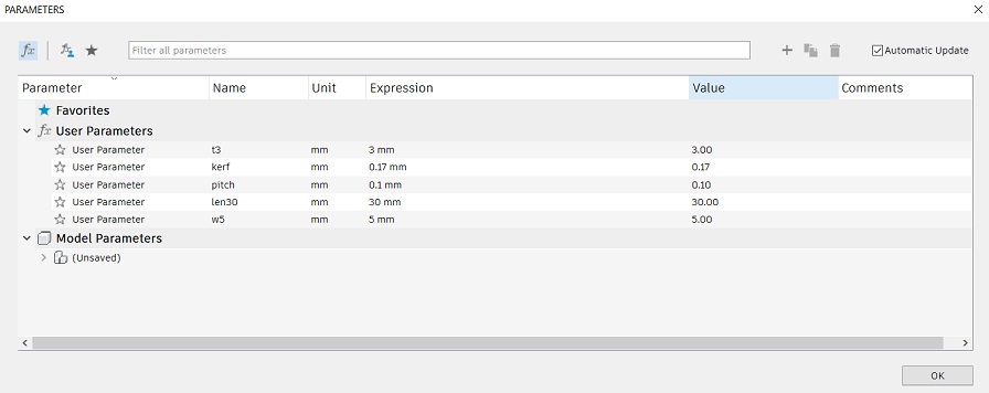
For example, if you click one of the dimensions in the following figure, you will see it’s the equation of parameter “kerf” divided by two. Since the kerf is pre-defined as 0.17mm, this offset outline is 0.085mm smaller than the original outline.
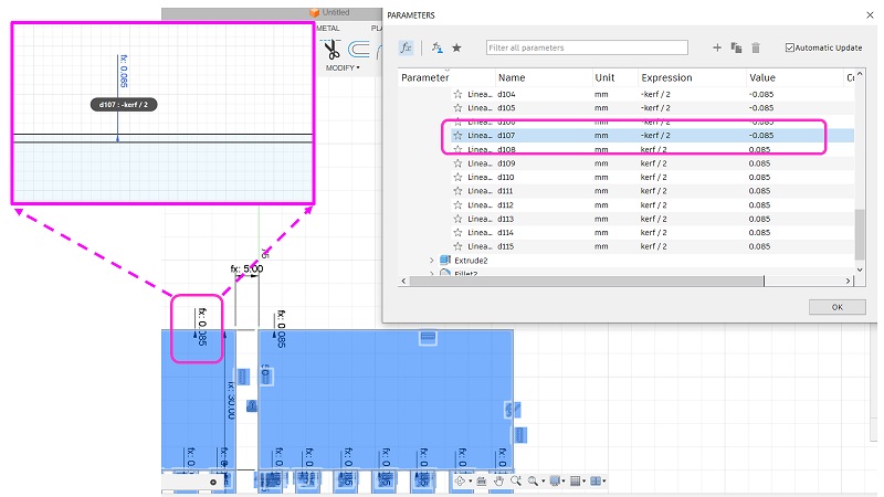
Similarly the pitches of the teeth are designed to decrease for one comb and increase for the other by every 0.1mm. This is also expressed by a multiplication of two parameters: “t3” and “pitch”.
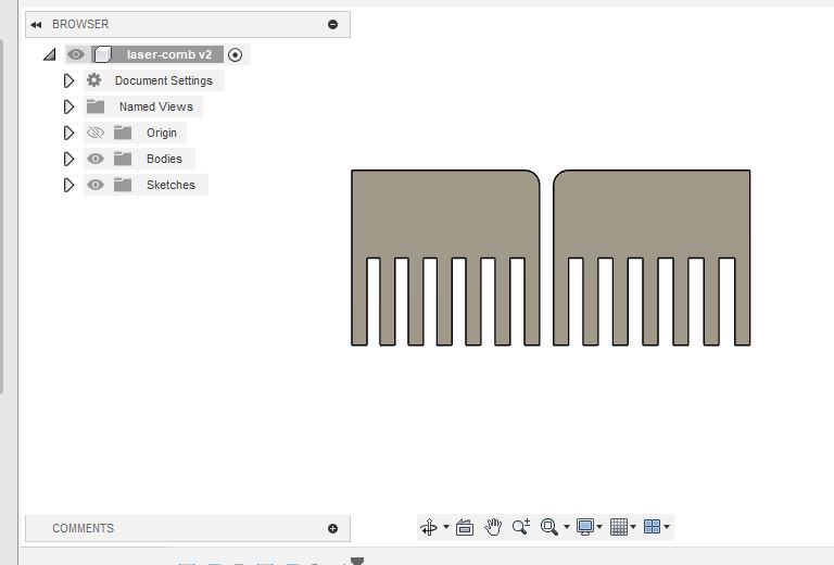
Once completing the sketch, we extruded all the profiles and made two bodies.
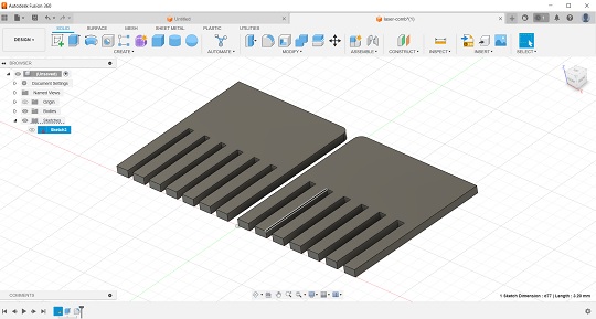
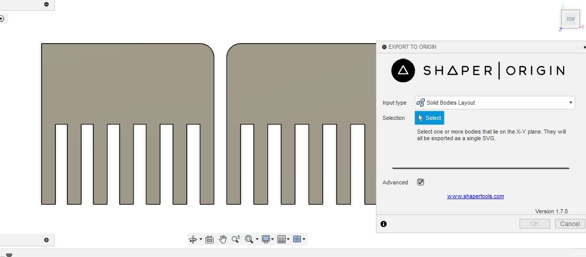
For exporting the outline data from this 3D design, we used the Shaper Utilities add-in on Fusion360. In the dialogue window this time, we selected “Solid Bodies Layout”, selected two bodies and created the SVG file for laser-cutting.
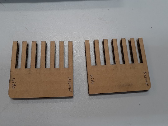
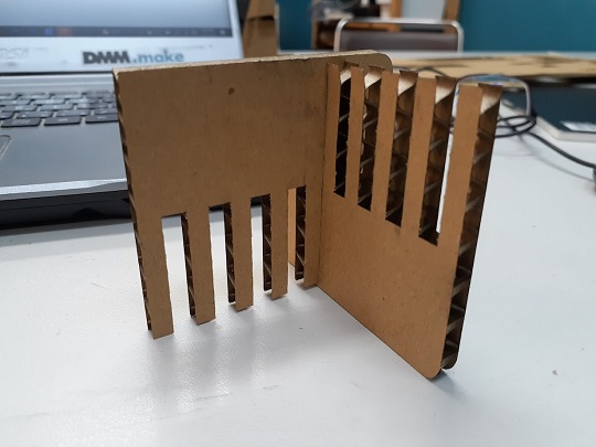
The above two snapshots show the results. By trying different combinations of the two combs, we tried to find the one which could hold the two combs tightly enough. In this case, we found that the combination of the second base of the fingers was probably the best. So we concluded that we set the clearance as 0.2mm (0.1mm x 2).
Clearance: 0.2mm
3. Conclusion
To recap, here is the summary of the parameters we are going to use for individual assignments of the week with Universal laser-cutter at our lab:
Power: 10 / Speed: 60 / PPI: 300 / Z-axis: 3.7
Kerf: 0.17mm
Clearance: 0.2mm
With these parameters, we proceeded to our individual assignments.
4. Problems We Faced: Document Recovery from Gitlab
It was the first group assignment for us on Gitlab. We had to work on documentation concurrently. If someone pushes his local repo files without git-pulling beforehand,the files in the Gitlab are overwritten by him and the other team members lose what they have written.
This happend to us in the middle of our documentation. Although I pulled, wrote and pushed the files last night, my group member worked on his documentation today while I was sitting back relaxed. He pushed his files without git-pulling beforehand. As a result, my documentation was erased.
This will happen to us and also other students. So I would like to write a little bit about my experience in recovering my documentation.
- First, I went to the FabLab Kannai site repo on Gitlab to find my last push. Once I found it, I clicked the commit number:
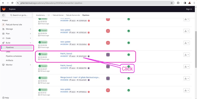
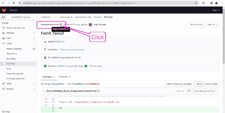
- Second, after clicking the commit number, I could move to the commit description. Then I clicked the “Copy commit SHA” icon:
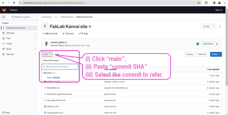
- Third, I went back to FabLab Kannai site repo and clicke “main” and pasted the commit SHA into the Search window. Then one commit was identified:
- Then, I opened the md file that I committed.
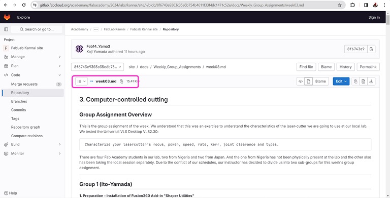
- Now that I could see what I wrote, the last step was to copy all the texts and paste them in my text editor.
Lessons Learned: As our instructor emphasized, we should always pull before push.
-----
Group 2 (Jidda-Ahmad)
This is a section being documented by Ahmad Ishaq Tijjani and Muhammad Jidda on the week3 group assignment titled computer controlled cutting.
As for our individual Assignment it can be found here Jidda Individual Assignment and Ahmed Individual Assignment
Characteristics of our laser cutter
In our lab we have Epilog Fusion Edge. It is a laser cutting and engraving machine known for its reliability and precision in various fabrication applications. With a power output of 40W and utilizing CO2 laser technology, it offers versatility in cutting and engraving a wide range of materials, including wood, acrylic, glass, and more. The Fusion Edge is equipped with advanced features and capabilities, allowing users to create intricate designs with speed and accuracy. Whether it’s creating custom signage, intricate artwork, or precise prototypes, the Epilog Fusion Edge delivers consistent and high-quality results, making it a preferred choice for professionals and hobbyists alike in the realm of laser fabrication.
This weeks assignment covers the following Aspects of computer controlled cutting:
- Focus
- Power
- speed
- Rate
- Kerf
- Joint clearance
These parameters are used for better results when cutting objects with accuracy and efficiency,various techniques are used to obtain them as discussed below.
Focus
Focus refers to the concentration of the laser beam at a specific point. Achieving proper focus is crucial for obtaining clean and precise cuts or engravings. The focus point is the narrowest part of the laser beam, and it determines the depth and width of the cut in the material.
In order to achive the right focus
- First, we set the machines focus laser tip using the provided focus red light by varying the bed heigth
- We then Varied the Z distance of the laser cutter’ bed to different length
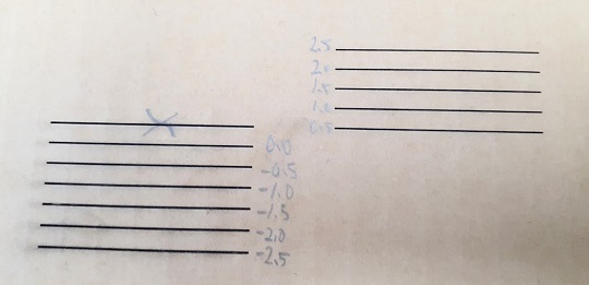
- While varying the distance, we cut several lines horrizontally according to the provided technique. Below we show the technique and results
Result :
- we noticed that since we are using cartons, therefore cutting horrizontally might have different effect as cutting vertically due to inner layer arrangement of the carton. we were cutting horrizontally similar to the layer arrangement which means some lines will be cut at much thickness than other lines.
- we then decided to run the same test but vertically such that all lines are cut at similar thicknesses.
- The focus was obtained to be at 6.8mm from the tip of the laser head
- The machine also has auto focus function based on the thickness of the material, which also gives a good result.
Power, Speed and Rate
- Power : This Is the amount of energy use by the machine at the point of operation (cutting,engraving etc)
- Speed : This Is simply how fast the machine is moving during operation
- Frequency : the rate at which the laser pulses are emitted by the laser cutter. It is typically measured in Hertz (Hz), indicating the number of pulses emitted per second. this parameter used to control the level of detail and precision in the output of a laser cutter.
Knowing the right values for these parameters will help immensly in getting efficient output from the machine’s operation.
In order to obtain these three parameters, we use a technique where by one of them is kept constant as the others are varried, we kept frequency at 50% and varied power and speed. then after obtaining a desired cut we then use the values and varied the frequency to see if improvements or optimisations can be made.
The pictures below shows the design concept and implementation of the technique. The first step was the design which we got from our instructor.
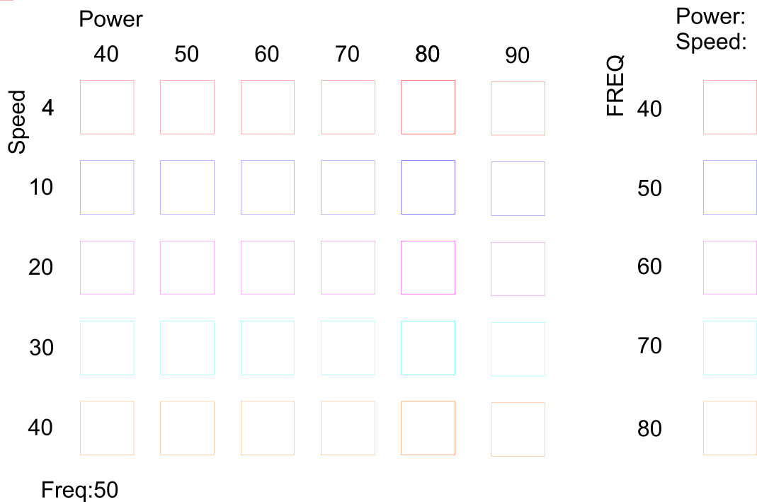
Next we did the cutting one column at a time while making changes to the values. we first fixed a power of 40 and then varied speed (bear in mind our frequency was kept constant at 50%).
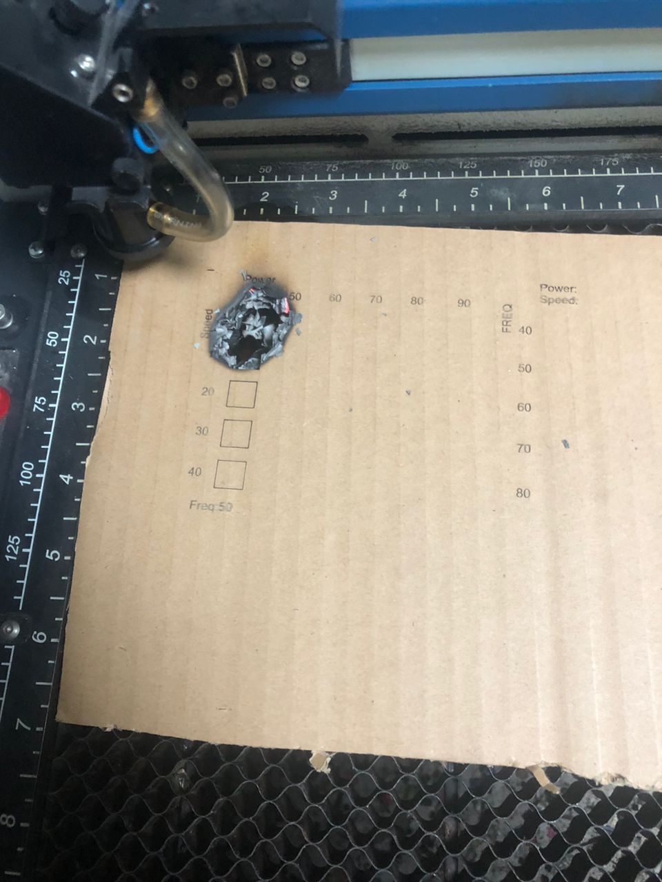
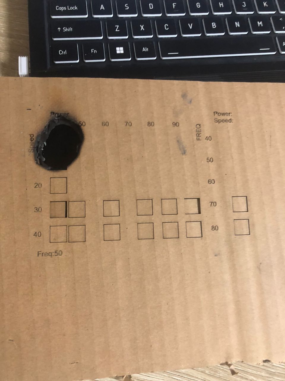
Result : From the test carried out the following Was observed:
- with cardboard at very low speed you can cook the board to ashes
- At a fixed rate, The best cut was observed to be when Power = 60 and speed = 30
- But after varrying PPI we noticed a better result at 30% frequency
- Hence our parameters are:
Power: acrylic -: 90%, plywood -: 80%, cardboard -: 60%
Speed: acrylic -: 20%, plywood -: 20%, cardboard -: 30%
Rate (frequency): acrylic -: 90%, wood -: 80%, cardboard -: 60%
Kerf
Kerf refers to the width of the cut made by a tool in a material.The width of the kerf is influenced by several factors, including the power and focus of the laser beam, the speed of the cutting process, and the properties of the material being cut. Understanding and controlling the kerf is important in laser cutting applications, especially when precision and tight tolerances are required. It’s worth noting that the kerf can vary based on the type of material being cut and the specific settings of the laser cutter. When designing for laser cutting, especially in applications where dimensional accuracy is crucial, it’s important to account for the kerf to ensure that the final piece meets the intended specifications. In practical terms, designers and operators may need to make adjustments to their digital design files or cutting parameters to account for the kerf and achieve the desired dimensions in the finished product.
Process and Result
We calculated the kerf of our laser cutter in the following steps using the values for power, speed, rate and focus obtained above
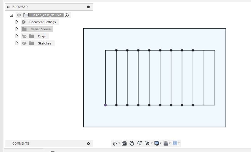
- We made a design of ten boxes in fusion 360 as shown below
- we then export the design using the shaper tool add-in found under utilities (after installation) and opened in corel draw.
- the total length of the ten boxes is 50 and the width is 100
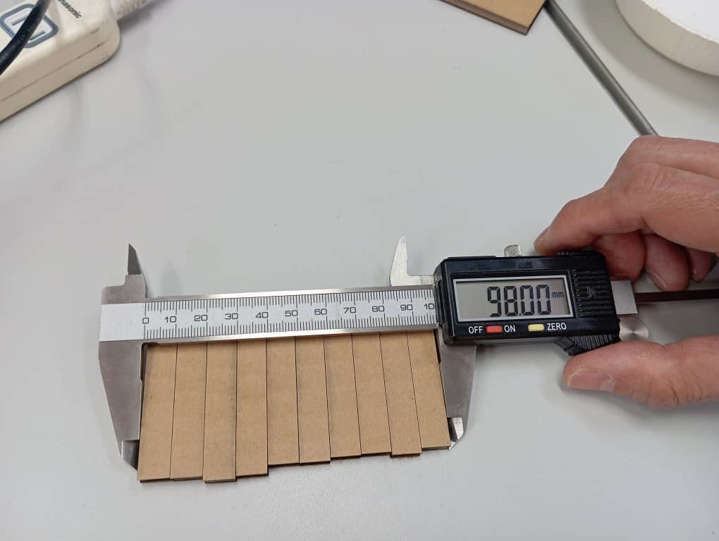
- we measured the total pieces after cutting and we got 98
- so 100mm-98mm=2mm is the total kerf for ten boxes hence our kerf is calculated to be 2/10= 0.2mm
Clearance
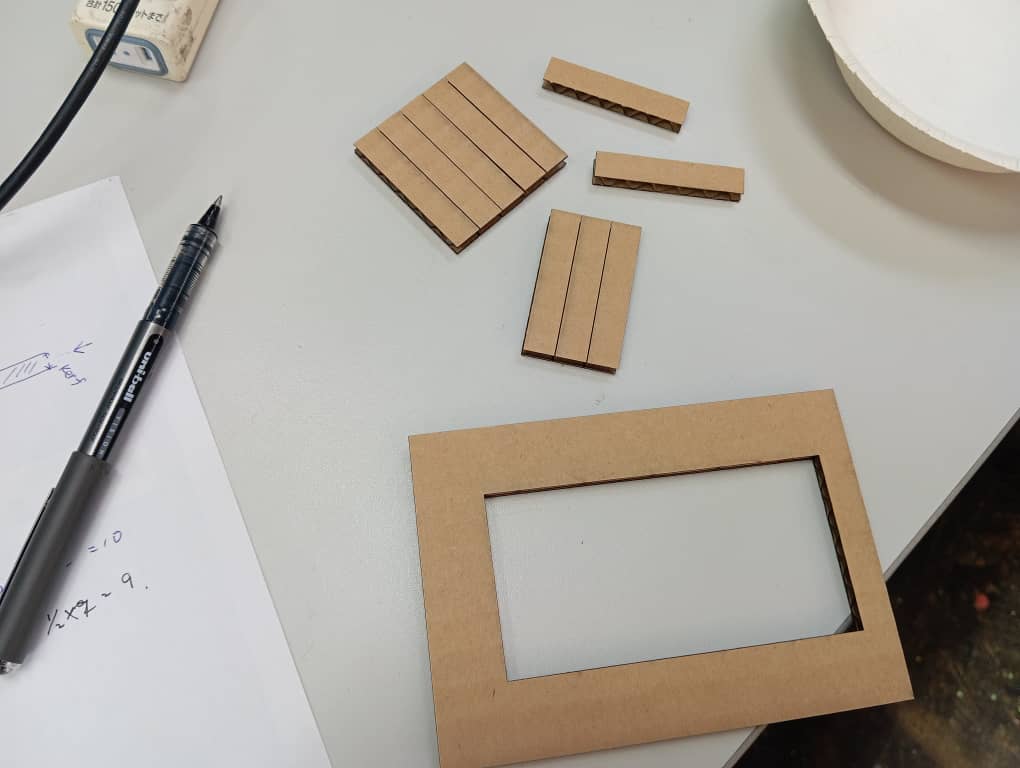
When making parts in a finger style, clearance is added so as to obtain free yet grip contact between two parts merging together. to Calculate that we used the comb concept where two comb like pieces are cut with one having the with of cut incresing incrementally from the starting point of (work piece thickness) while the other comb has decreasing values.
we start by designing the two combs in fusion 360 using parameters such as thickness, kerf, width etc as shown in the figures below.
Shaper Utility tool is used to export the vectors to .svg format which we used on corel draw for cutting out the parts.
After the cut, we inserted our carton to test which grip is preferable and our decission is 0.1mm
Conclusion
The activity was fun and interesting, we were introduced to new ideas and we really appreciate.
Our results are as follows
- Power: acrylic -: 90%, plywood -: 80%, cardboard -: 60%
- Speed: acrylic -: 20%, plywood -: 20%, cardboard -: 30%
- Rate (frequency): acrylic -: 90%, wood -: 80%, cardboard -: 60%
- Kerf = 0.2mm
- Focus = 6.8mm from the tip
- Joint Clearance = 0.1