This week's learning focused on computer-controlled cutting techniques, encompassing a variety of tools and processes for precision fabrication. In the realm of cutting tools, we explored options like knives (including Cricut, Cameo, and ultrasonic cutters), laser cutters (such as Epilog, Universal, and Trotec), plasma cutters (like Forest Scientific and Torchmate), waterjets (including OMAX and WAZER), and hot wire and wire EDM machines for specialized cutting needs. Each tool offers unique capabilities and applications, ranging from intricate detail cutting to high-speed fabrication across a diverse range of materials.
This week's assignment is about understanding laser cutter and vinyl cutter machines in our lab.
For details on the characteristic of our laser cutter goto our Group assignment page
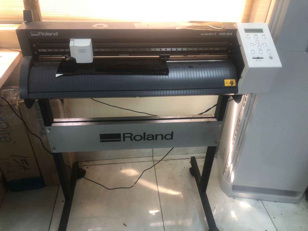
The vinyl cutter we have in our lab is Roland CAMM-1 GS-24 is a 24" desktop vinyl cutter designed for creating signs, decals, stickers, car graphics, window tints, and more. It’s easy to use, reliable, and produces professional-quality graphics.
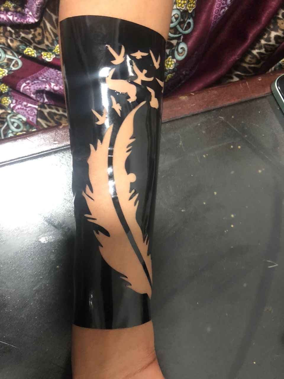
For the assignment this week, I cut Git and Apple logos and Henna design. The pictures were gotten online and prepared for cutting in CorelDraw.
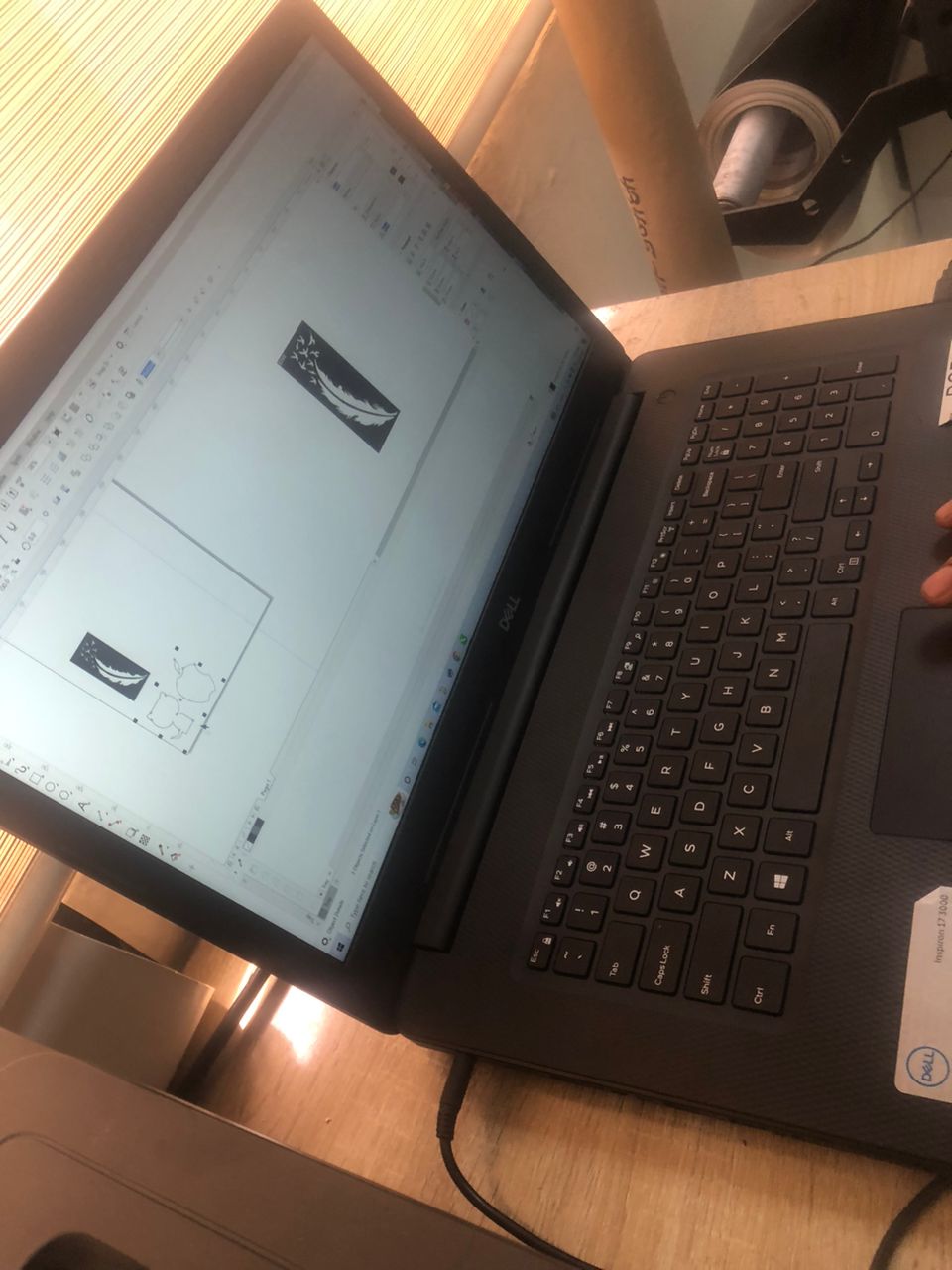
Cutting process
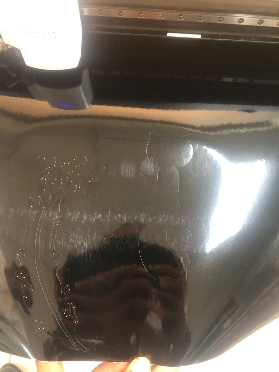
After cutting I removed the stickers and pasted them as you can see bellow
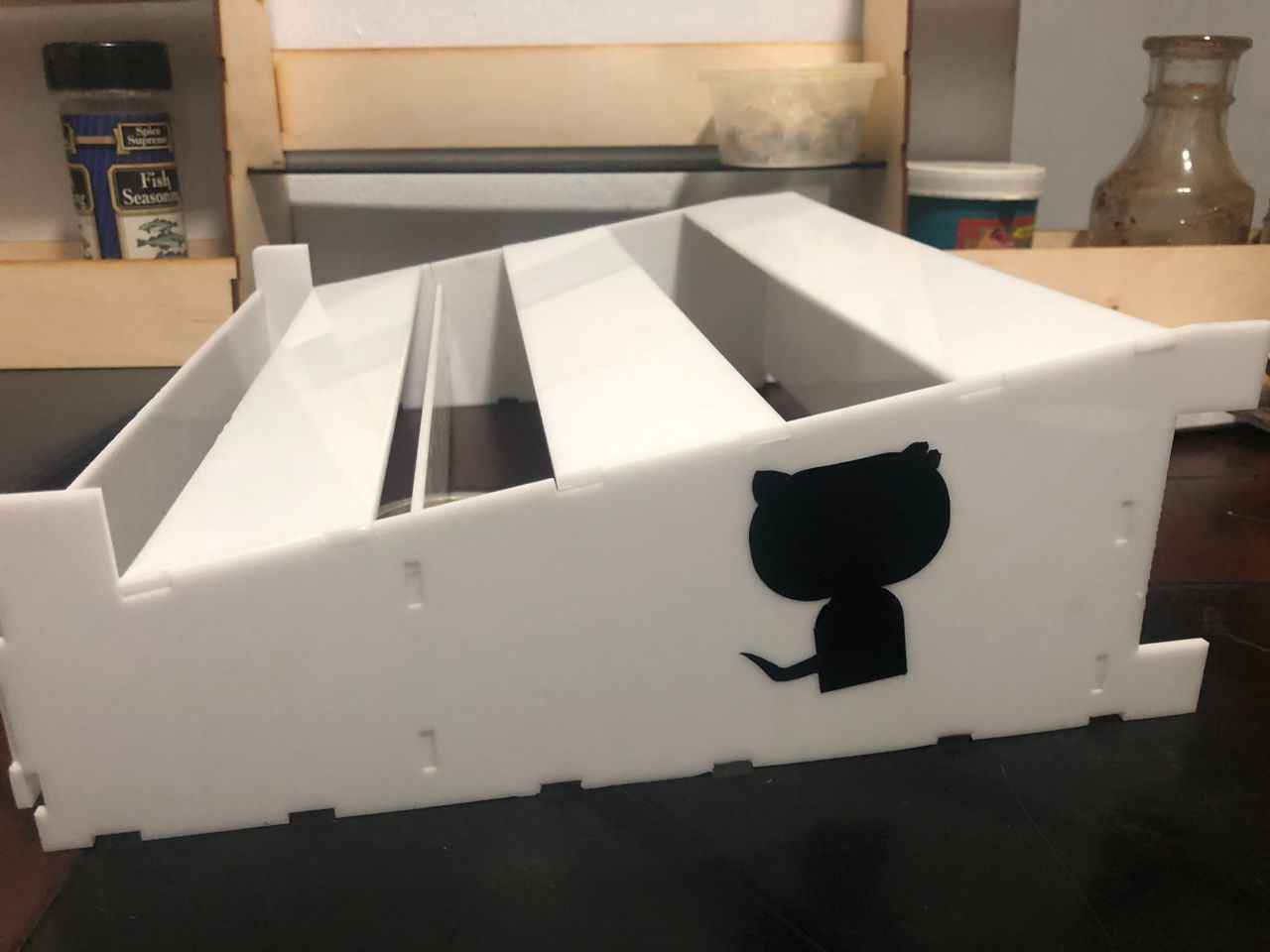
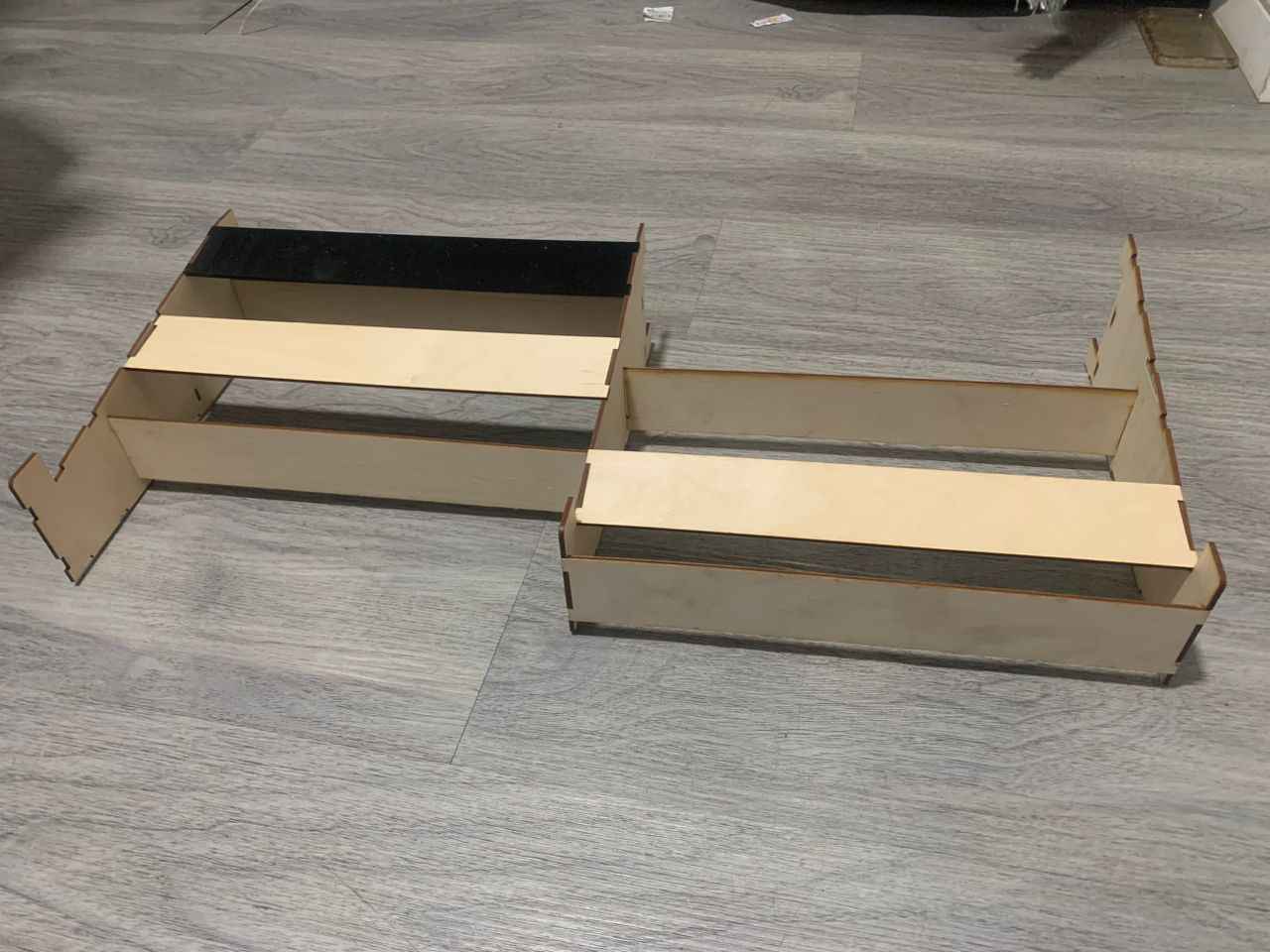
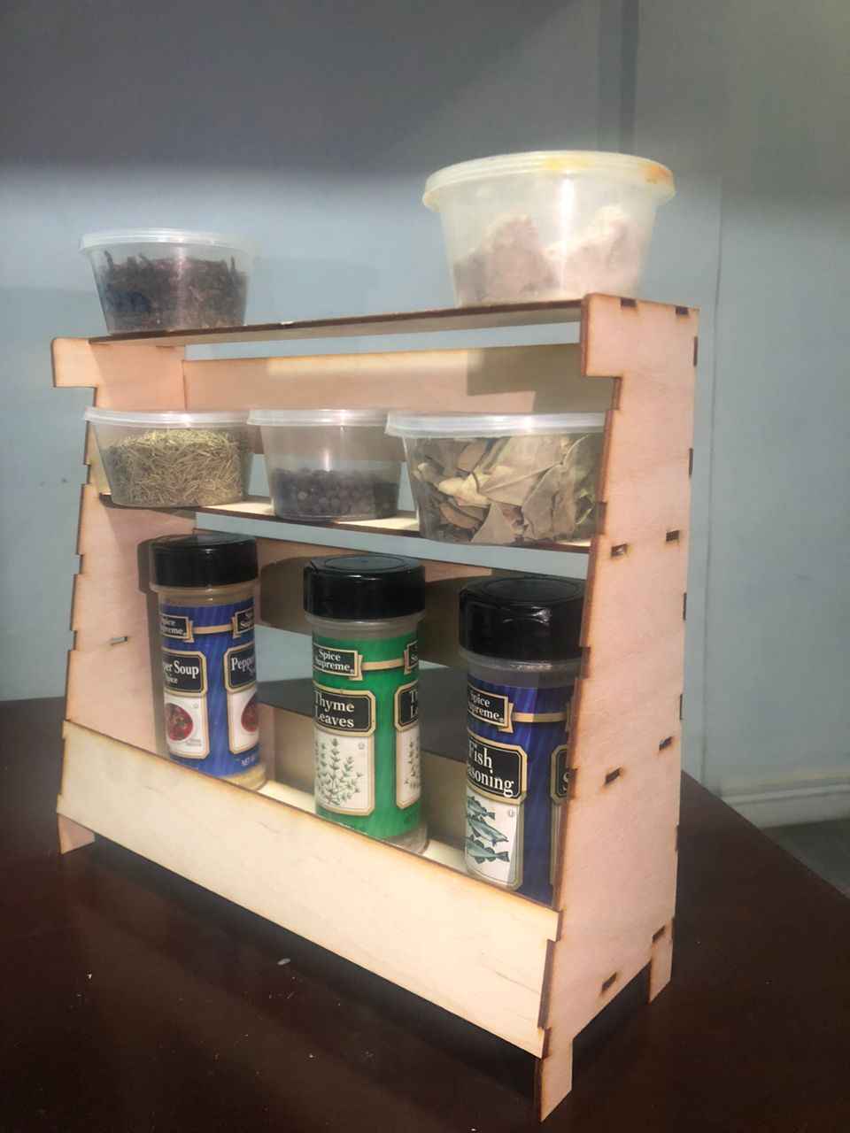
The second assignment for this week is to characterize the laser cutter in our lab, design a parametric construction kit that can be assembled in multiple ways and cut it with the laser cutter.
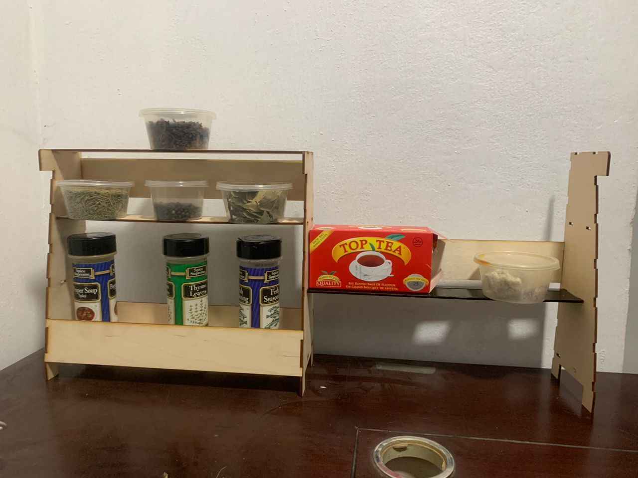
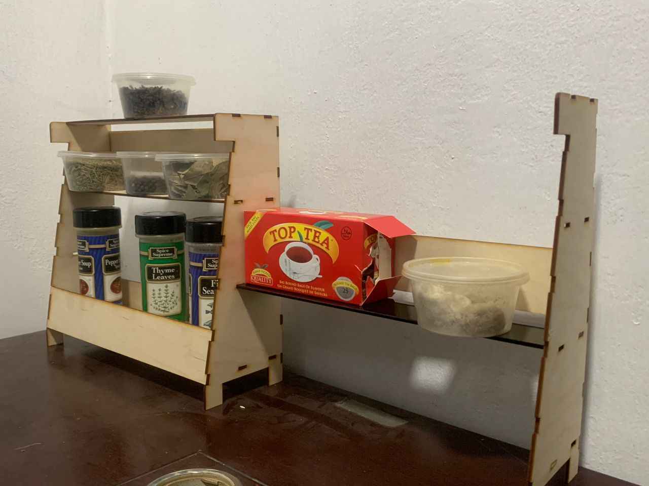
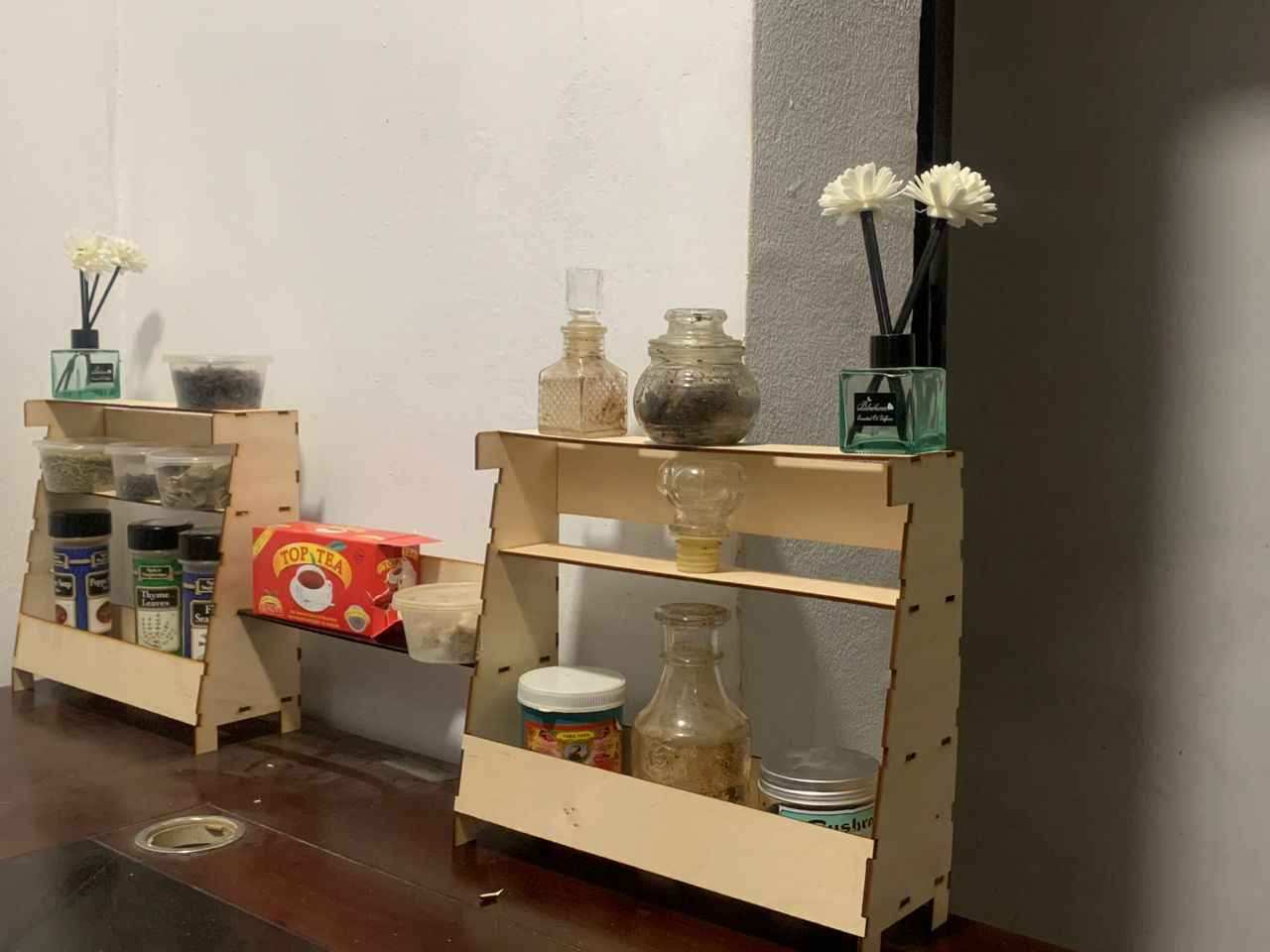
To do this I designed two (2) panels that can be assembled as a laptop stand, shelve, foot rest etc. and I called this kit Vuvuti
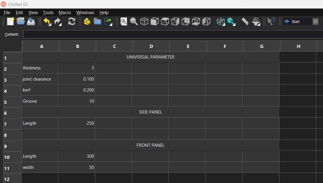
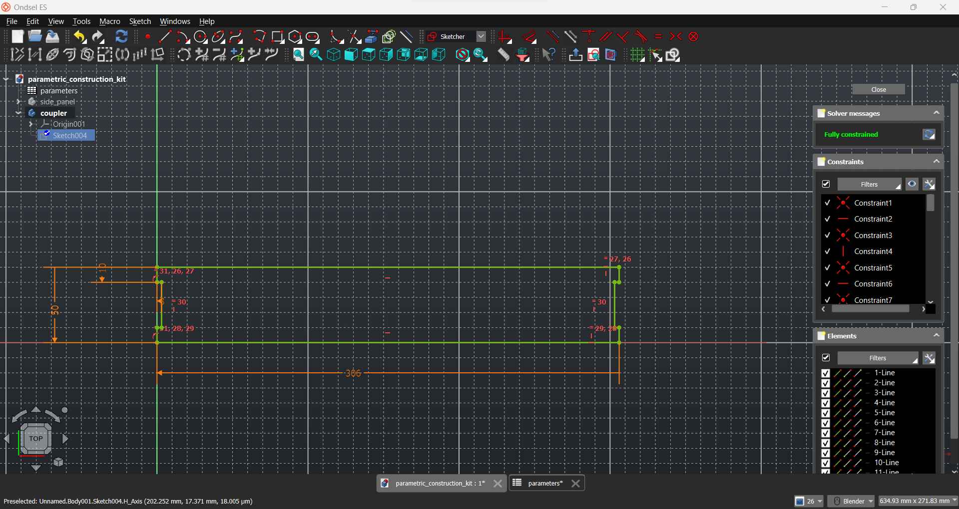
I used an Onsel/FreeCAD spreadsheet to set up the design parameters such as joint clearance, kerf etc. these parameters are used to achieve a proper fit of the panels during assembly
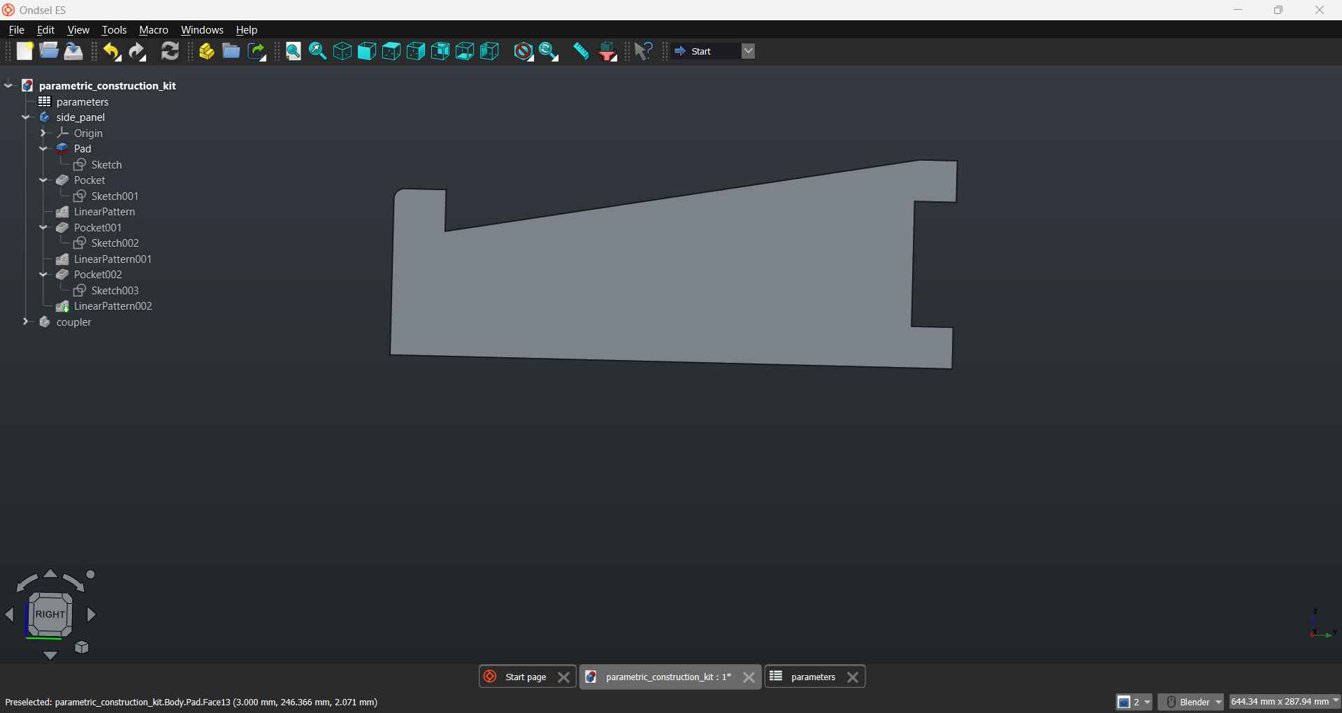
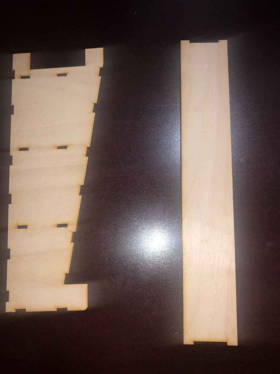
Designing the side panel
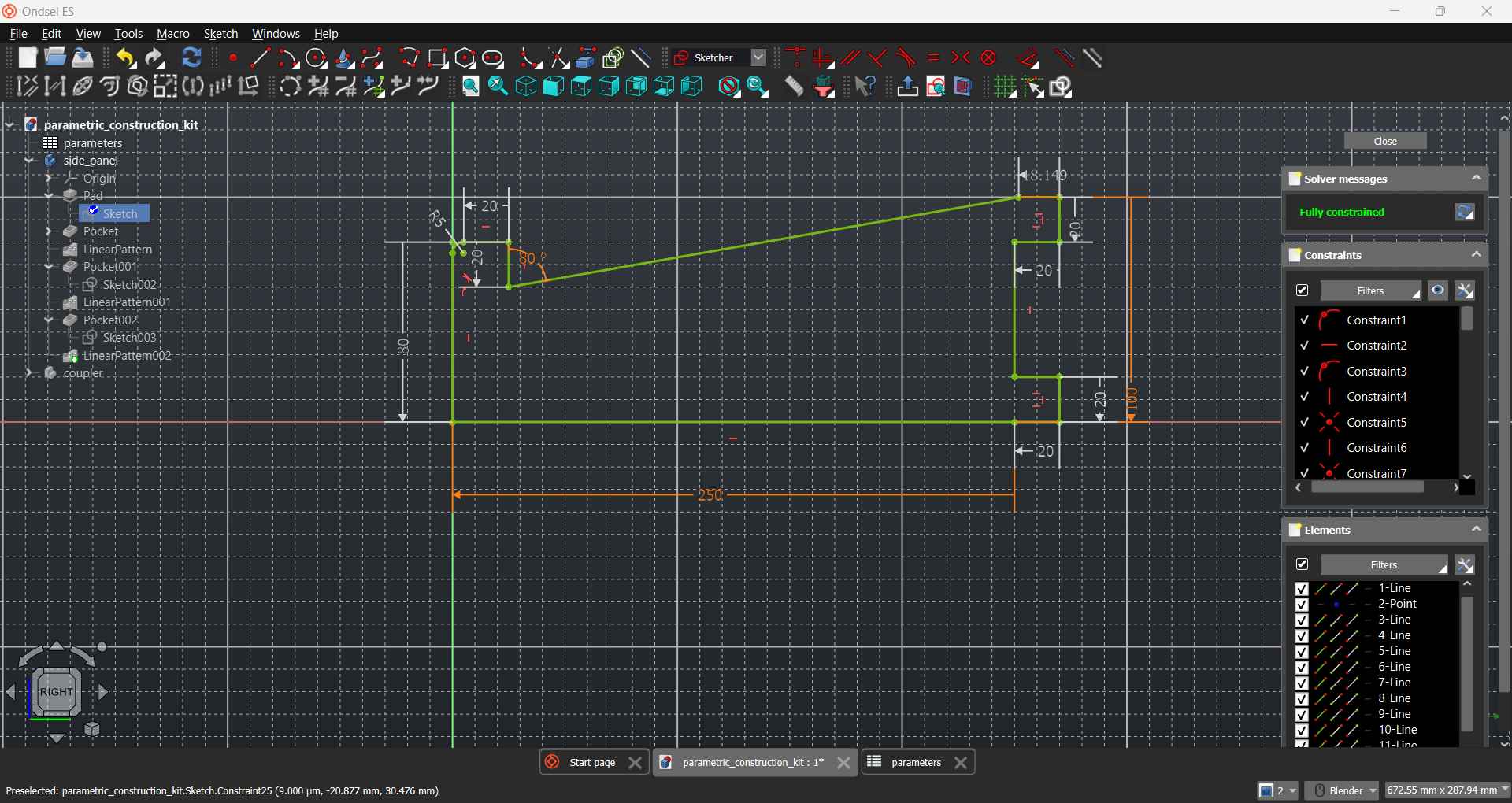
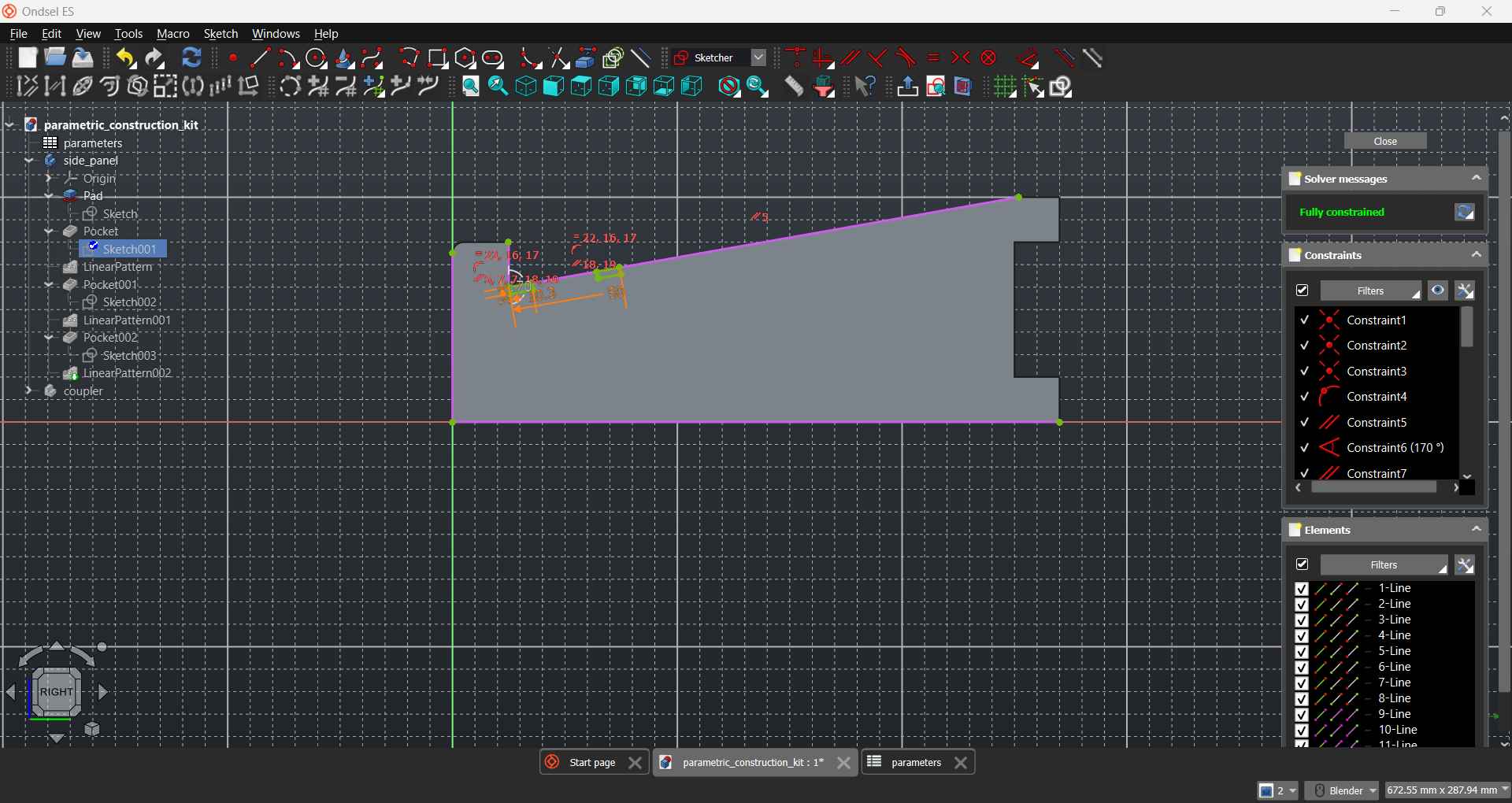
Adding the grooves
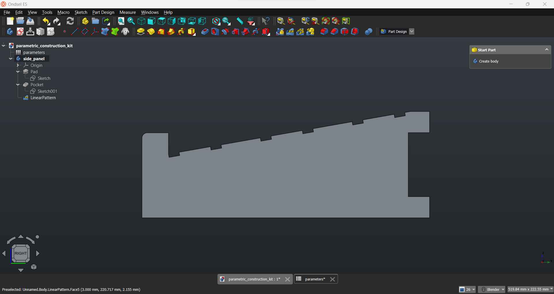
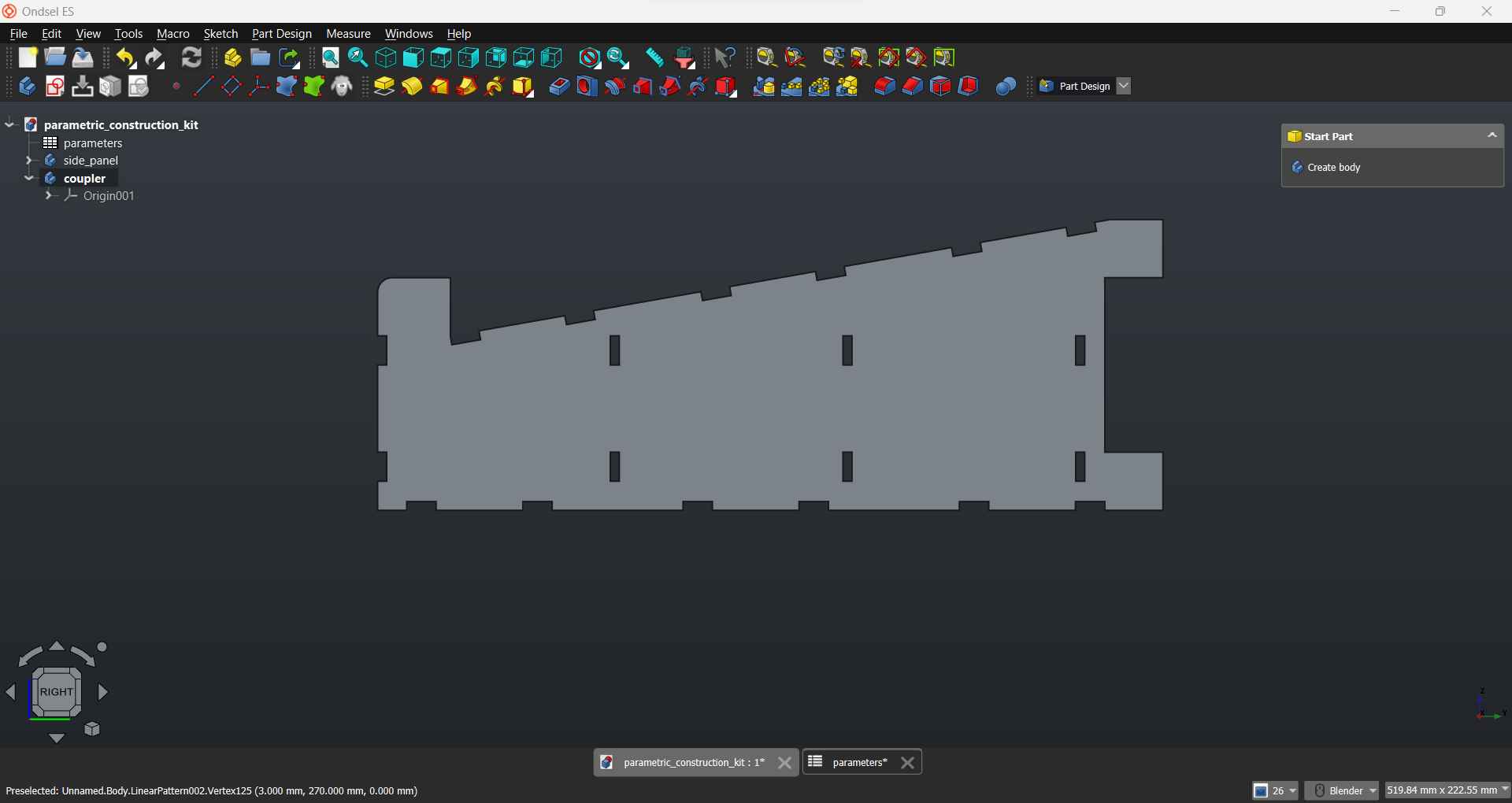
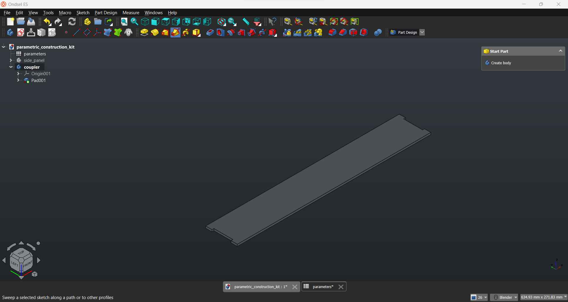
Designing the coupling panel
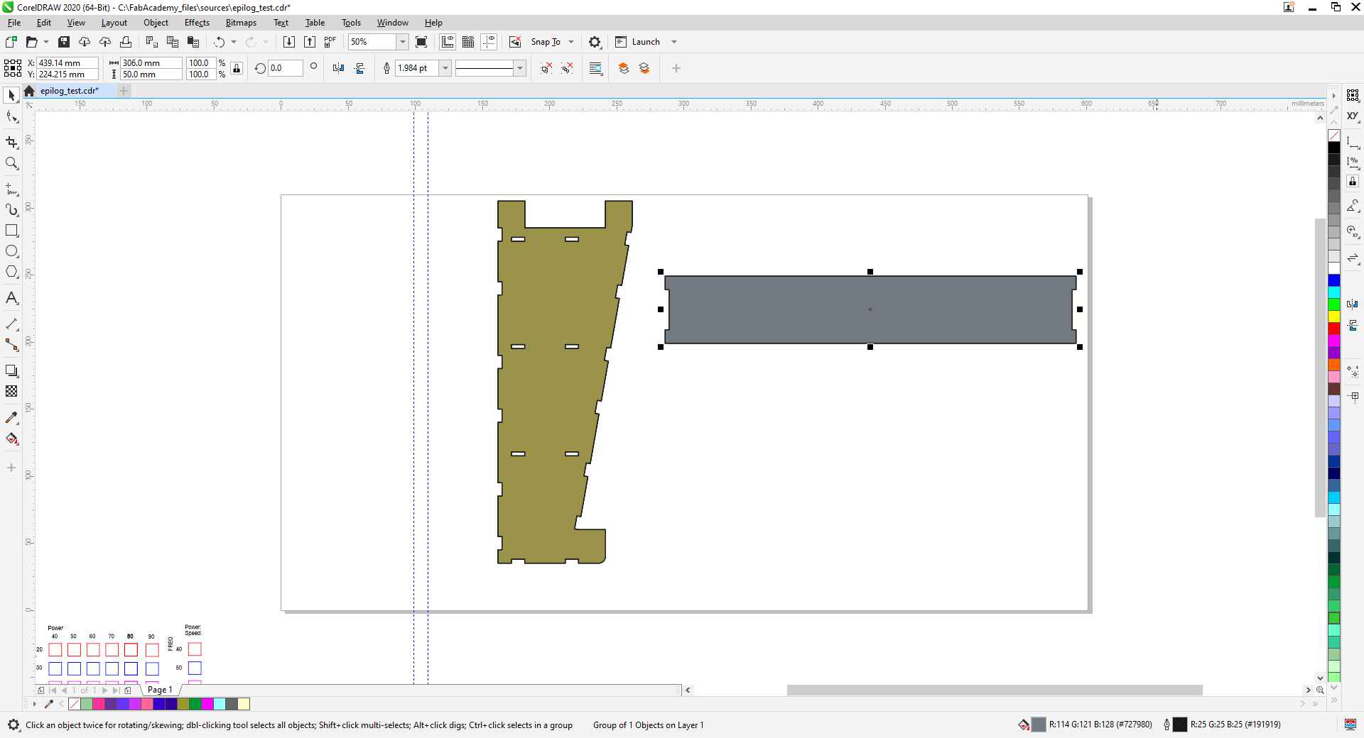
After completing the kit design I export the faces as SVG and import them into CorelDraw
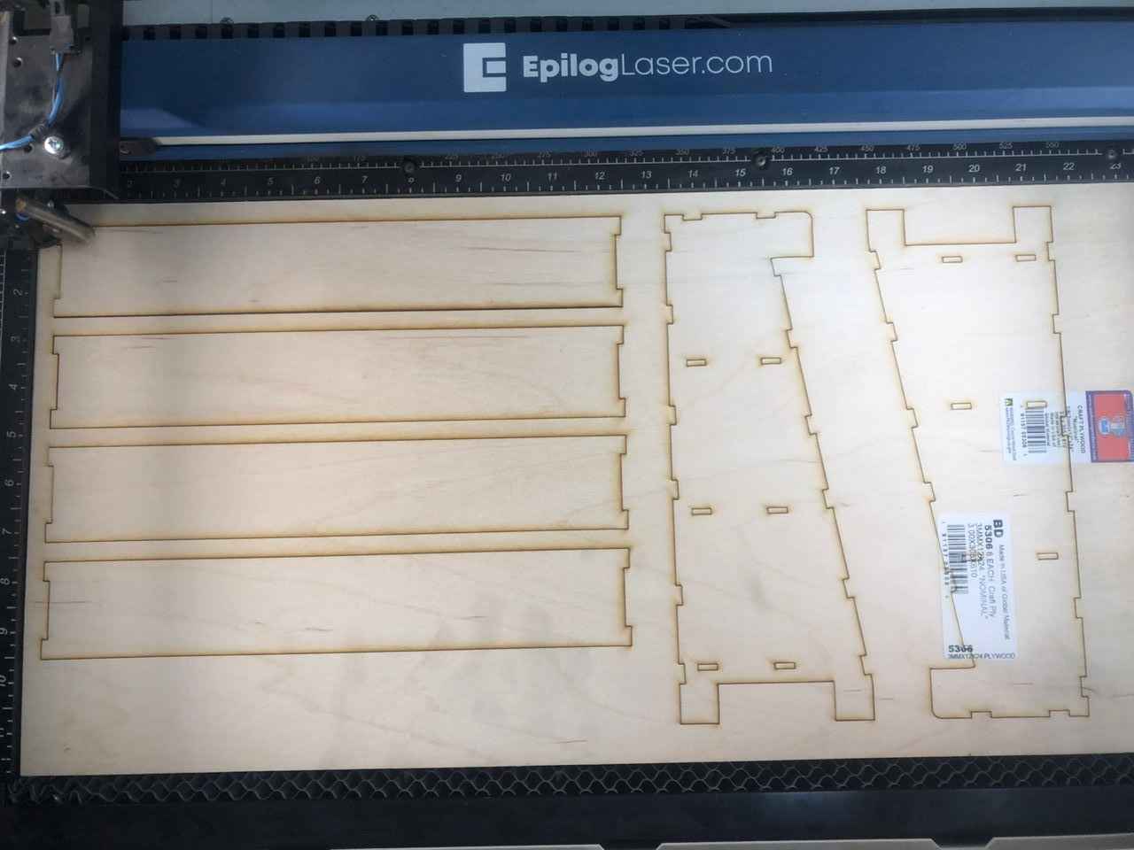
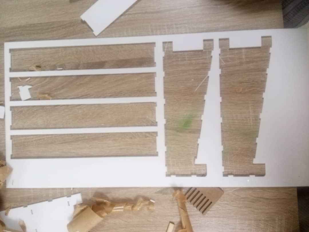
Then I started cutting. I cut the same kit with plywood and acrylic materials using the following settings:
| Material | Power % | Speed % | Rate (Frequency) % |
| Plywood | 80 | 20 | 80 |
| Acrylic | 90 | 20 | 90 |
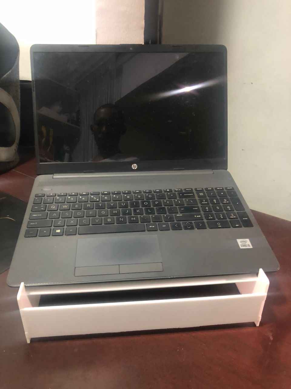
Laptop Stand
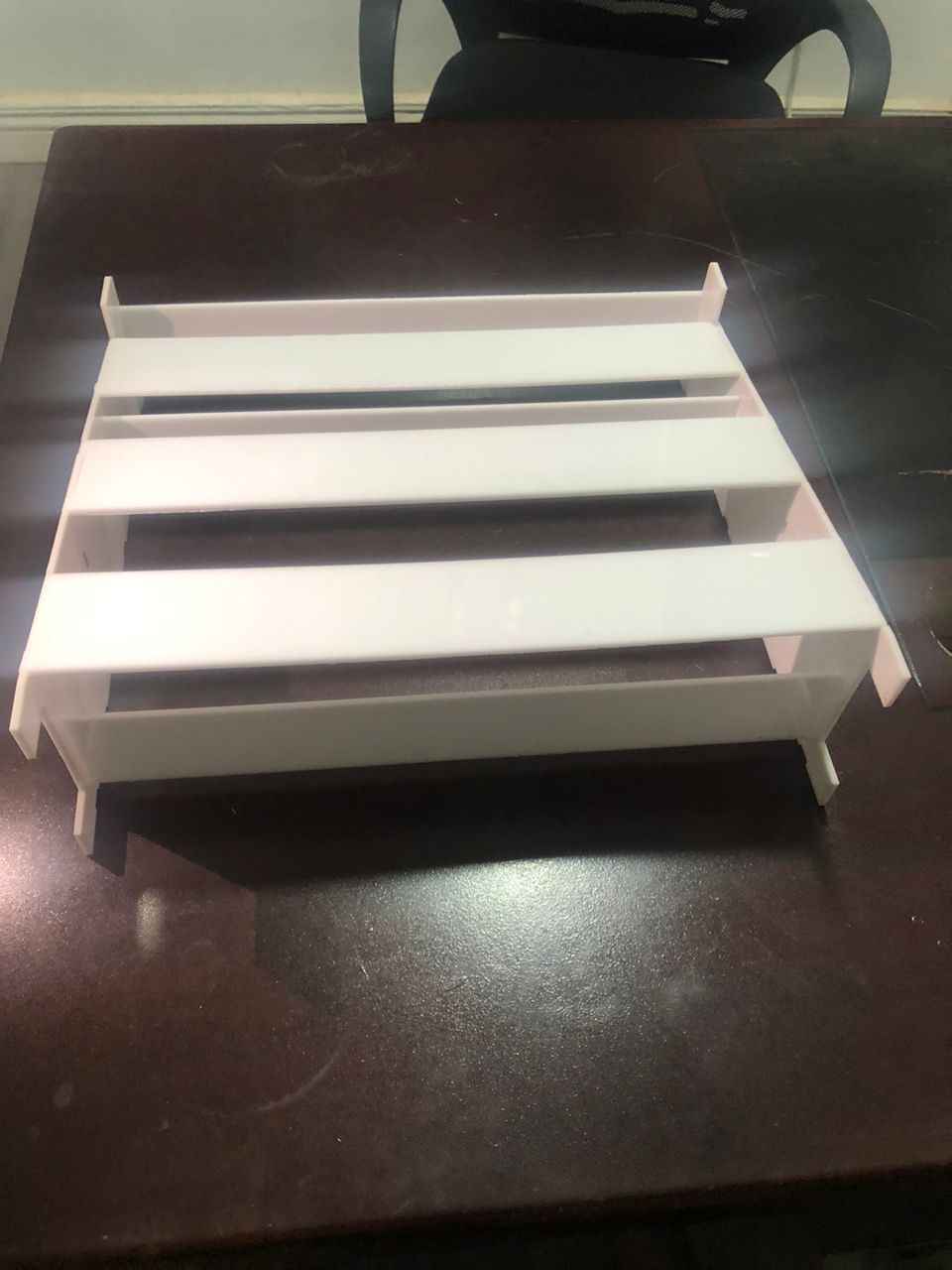
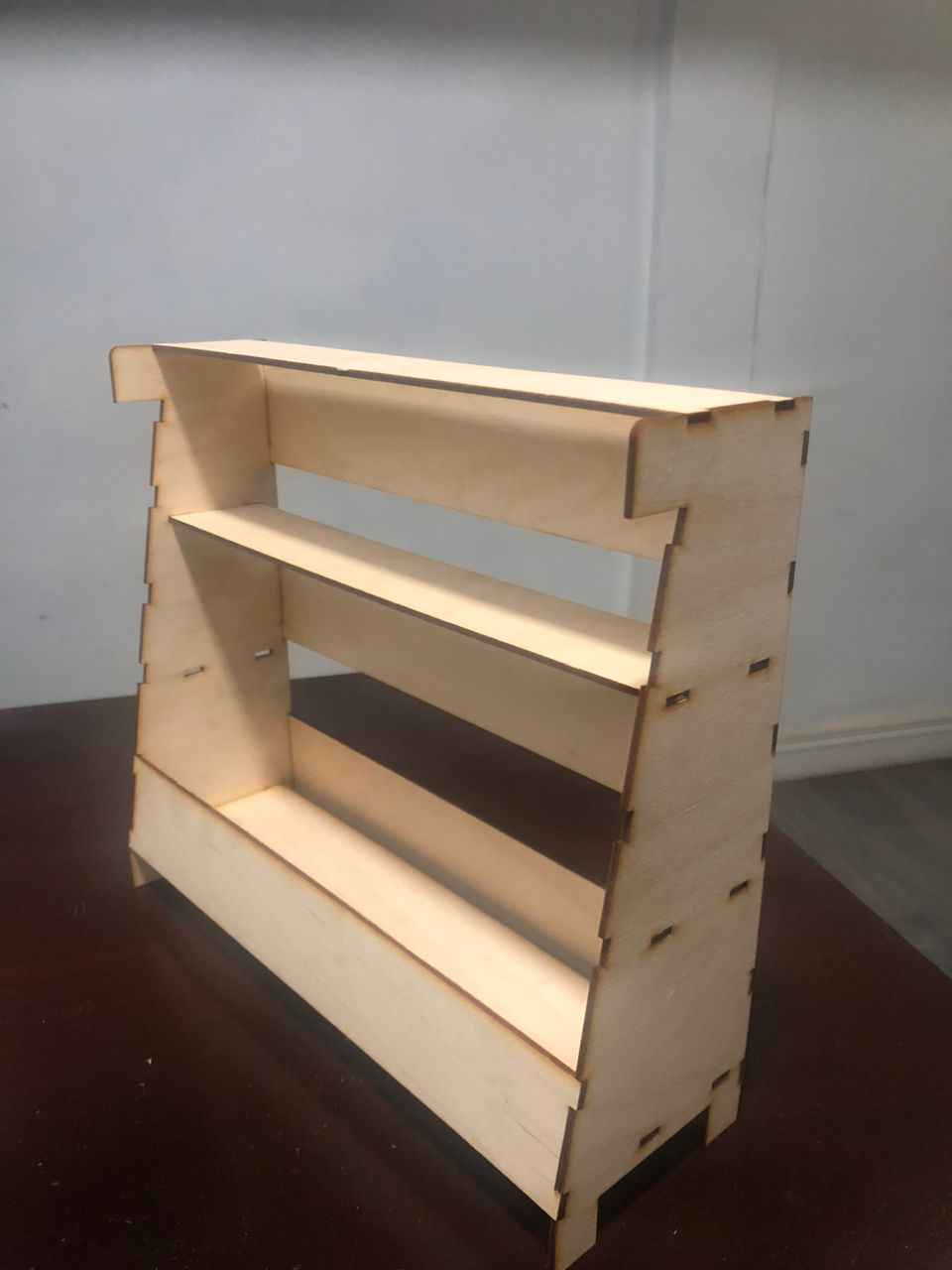
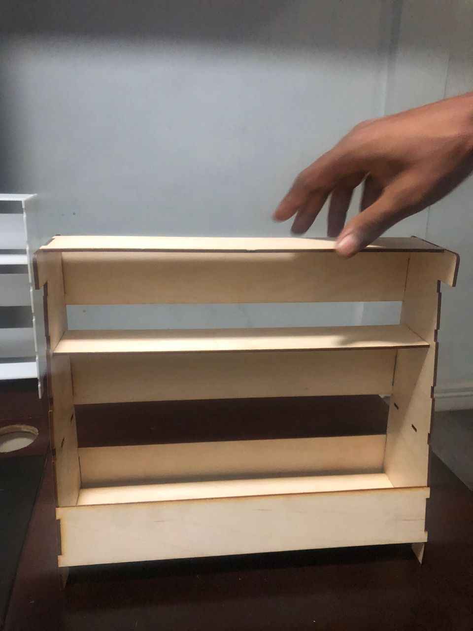
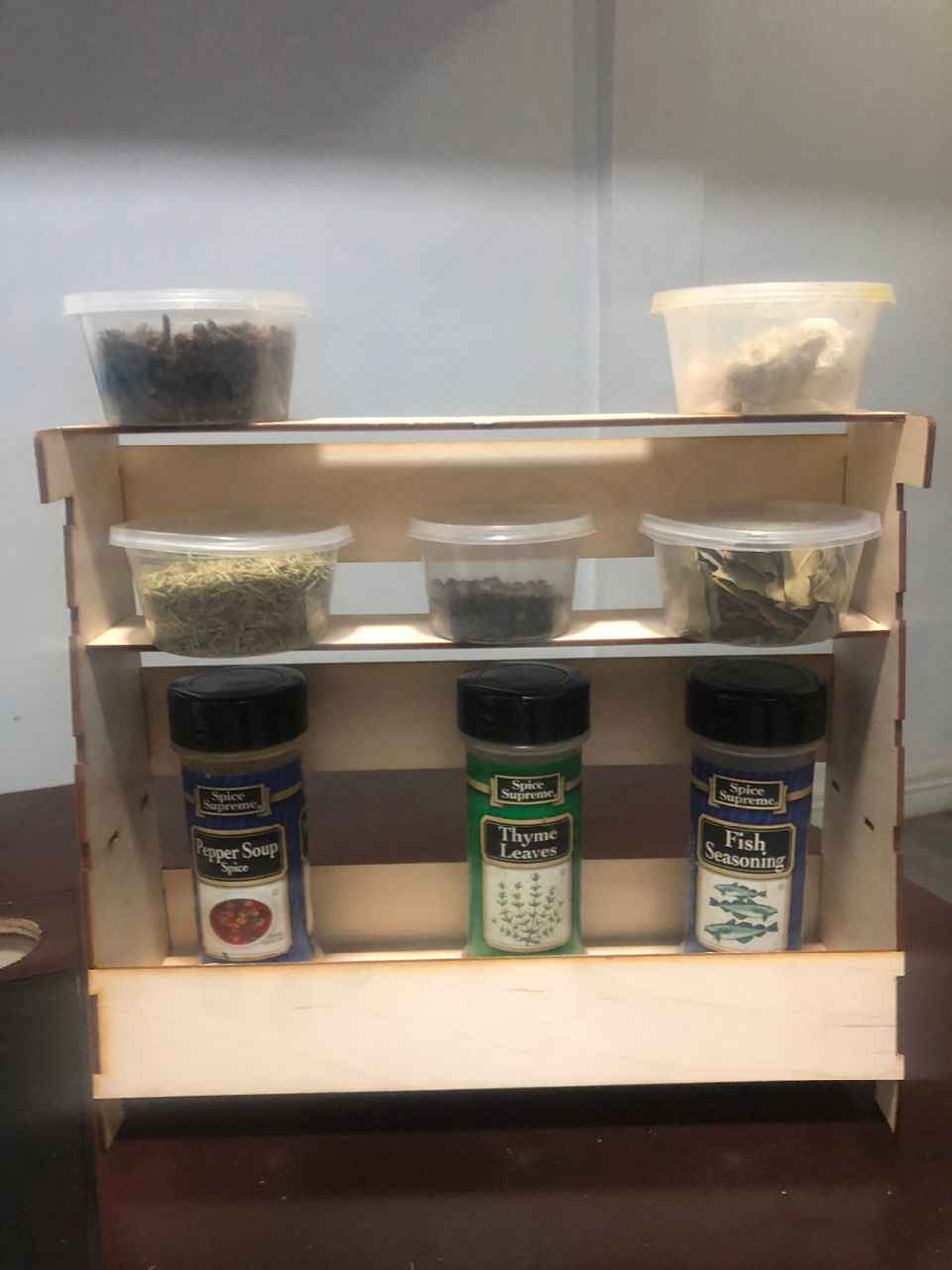
Shelve
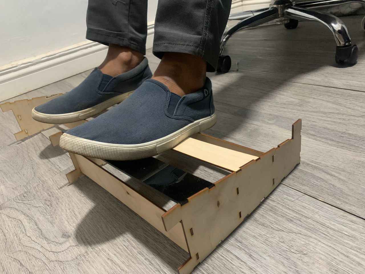
Foot Rest