I like to develop a fish feeder as my final project because I have a fish pond where I rear fish for commercial activities. This machine will be designed to provide automatic, precise, and scheduled feeding for my fish.
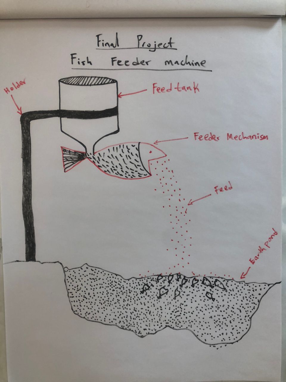
Dispense fish feed into a fish pond based on a scheduled time, some sensors etc.
Similar automated fish feeding systems will have been developed previously for aquariums. This project will build upon existing solutions like the one done by Neville Govender (Fab Academy 2018) and FFAZ Automatic Fish Feeder.
A programmable feeder unit equipped with sensors and actuator to feed my fish. The feeder unit will be controlled by a microcontroller, and users will be able to customize feeding schedules and portion sizes.
Materials and components will include:
The components can be sourced from various electronics suppliers and hobbyist stores both online and offline.
Costs will vary depending on the specific components and suppliers chosen.
The feeder unit, including the enclosure and mechanisms for dispensing food, will be made, assembled and integrated into the system.
Processes involved will include:
Successful integration of sensors and control mechanisms for automated feeding is anticipated. Challenges may arise in calibrating sensors and ensuring accurate dispensing of food.
The system will be evaluated based on its ability to maintain optimal feeding schedules and provide a user-friendly interface for customization.
| Task | Activities | Jan | Feb | Mar | Apr | May | Jun |
|---|---|---|---|---|---|---|---|
| Concept | Ideation | x | x | ||||
| Sketch | x | x | |||||
| Design | CAD | x | x | ||||
| Circuit Board | x | x | x | ||||
| Coding | Embedded | x | x | ||||
| User Interface | x | ||||||
| Construction | Metal work | x | |||||
| System integration | x | ||||||
| Testing | Extruder test | x | |||||
| Field test | x |
I used OndSel CAD to design the FFM consisting of a pole, extruder, circuit board container and the main container
The pole is 1.5m long and will be anchoring the remaining parts of the machine

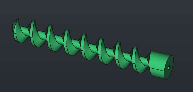
This is a T shape pipe that contains a screw to drive the feed and a propeller to dispense the feed.
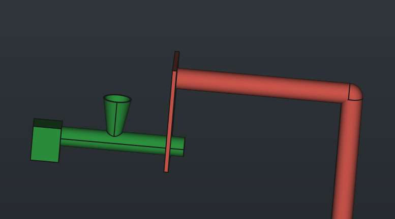

This contains the main circuit board and the battery.
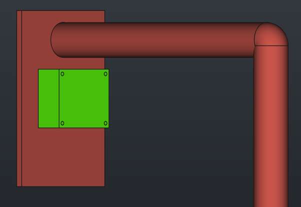
The container holder is connected to the pole plate through a Load Cell to act as a weight sensor.
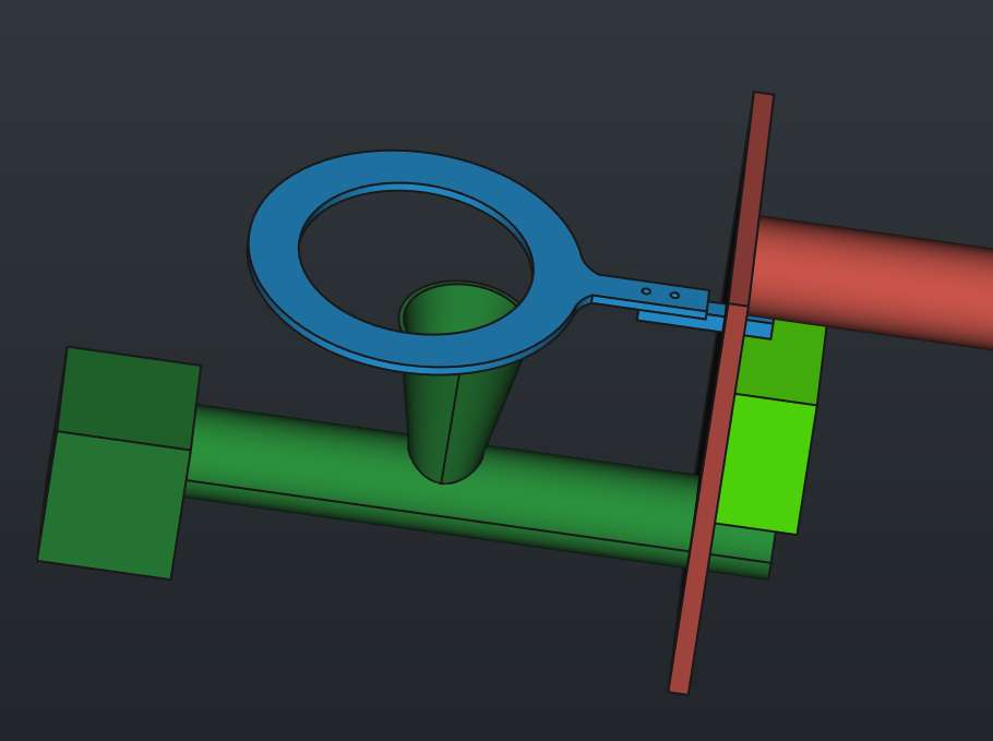
The container that holds the feeds
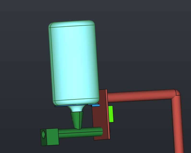

3D Model:
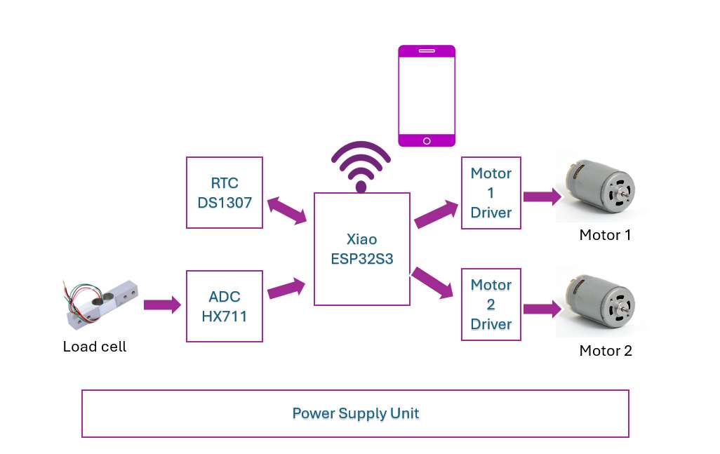
A complete details on how I design the circuit is found in Week 8: electronics design
The circuit is based on this block diagram:
Main Circuit Board Bill of Material
| SN | Item | Qty |
|---|---|---|
| 1 | Capacitor (10uF) | 2 |
| 2 | Voltage regulator (AMS1117-5.0) | 1 |
| 3 | Resistor (10k, 100) | 4, 2 |
| 4 | Diode (CDBM1100-G) | 2 |
| 5 | Seeeduino XIAO ESP32S3 module | 1 |
| 6 | IDC connectors (CONN HEADER SMD 4POS 2.54MM) | 5 |
| 7 | Mosfet (RFD16N05LSM9A) | 2 |
| 8 | Connectors (GCT_BG300-06-X-X-A_REVC) | 2 |
I have implemented the code bit by bit head on to the following pages for more details:
The complete code can be downloaded under the Sources section
The pole was constructed from a galvanized pipe and a metal sheet.

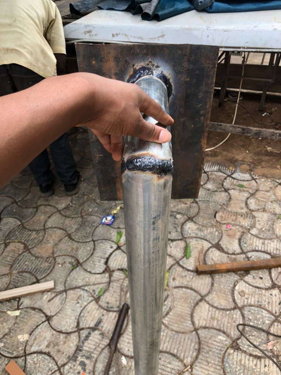
The videos below shows how the extruder was constructed:
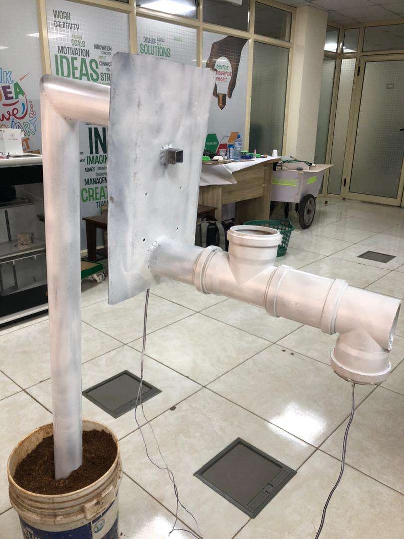
I used white spray paint to give it nice white color
The main PCB board, RTC module, HX711 ADC converter module for load cell and the battery is packaged within the circuit board container nicely as shown below:
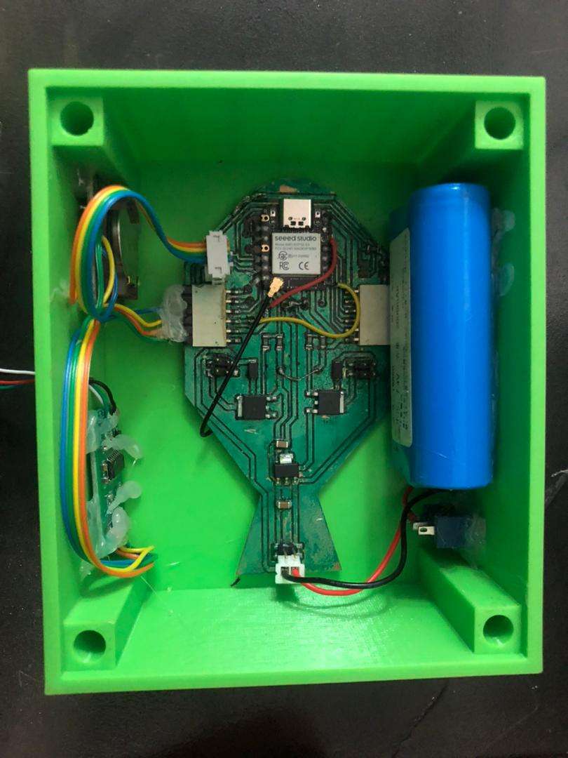
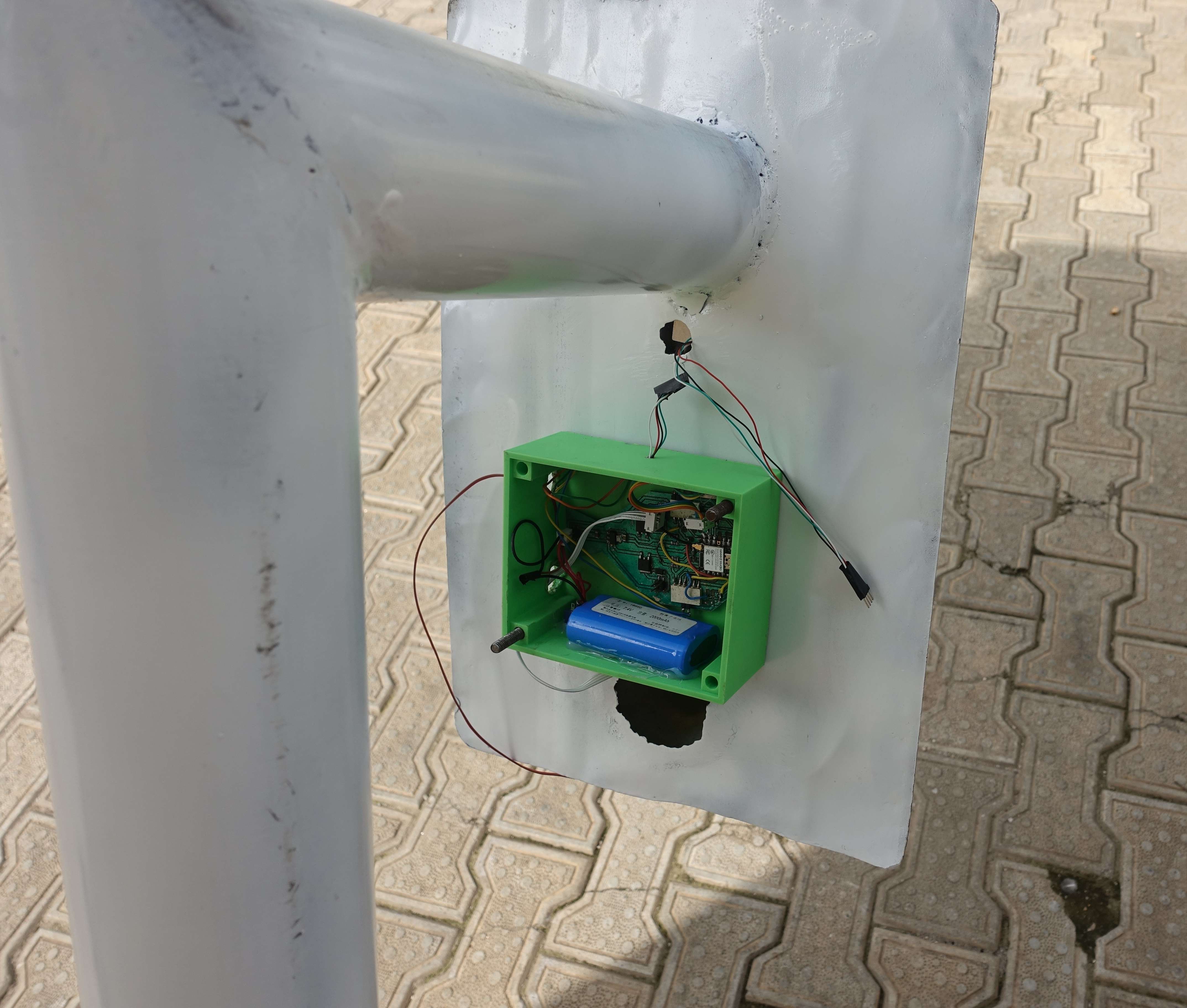
A 3 watt solar panel is added to charge the battery.
To cover the extruder and make it looks nice, I cut a fish-like shape of wood using ShopBot

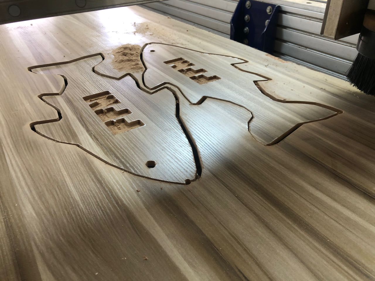
The same shape was cut from a white sticker using vinyl cutter to coat the wood
it was then attached to the opposite sides of the extruder
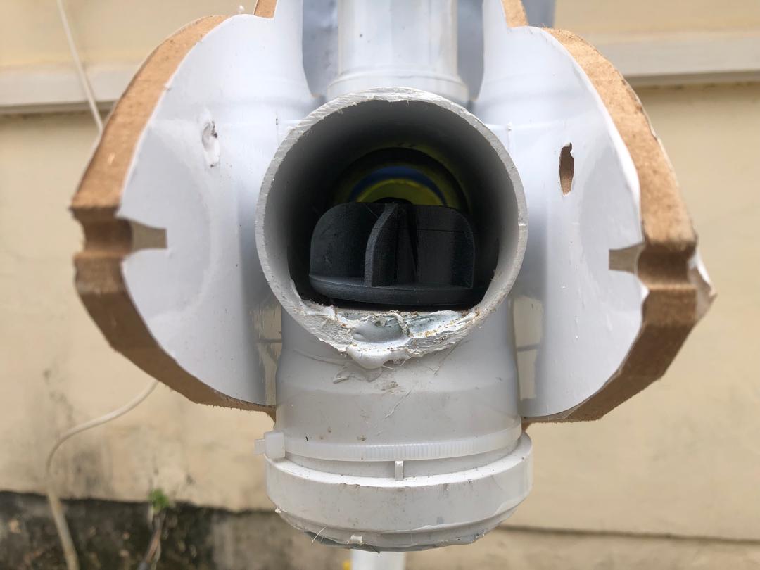
this is the complete assembly
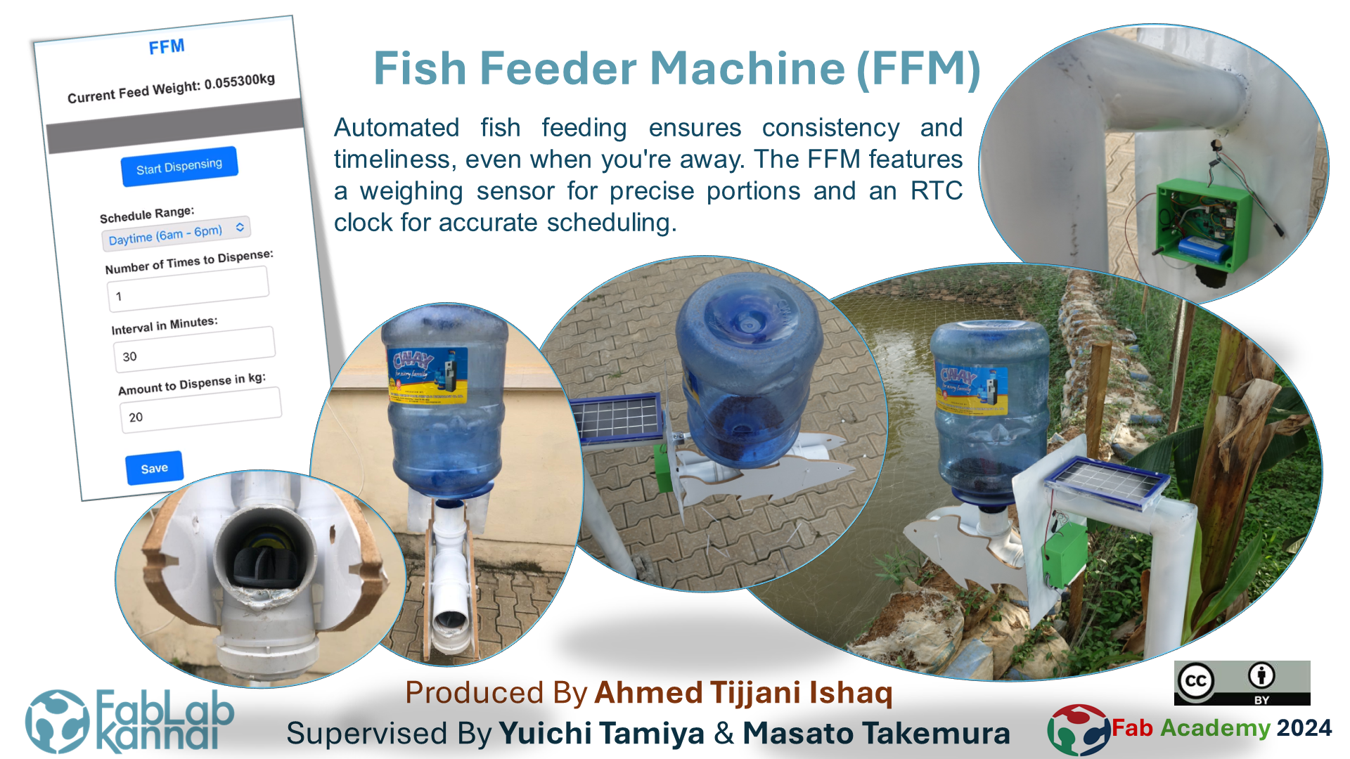
Here I control feed dispensing from a mobile interface
Installed at the farm:
| SN | Item | Qty | Cost ($) |
|---|---|---|---|
| 1 | Main Circuit Board | 1 | 15 |
| 2 | Weight sensor | 1 | 2 |
| 3 | RTC module | 1 | 3 |
| 4 | Galvanized pipe | 1 | 10 |
| 5 | PVC pipe (@ local store) | - 2 T-junction - 1 socket |
3 |
| 6 | Solar panel | 1 | 5 |
| 7 | Li-ion battery | 1 | 3 |
| 8 | Water Dispenser Bottle | 1 | 1 |
| 9 | Miscellaneous (screws, copper board, hot glue, etc.) | - | 10 |
| Total | 52.00 | ||