Electrical safety is paramount in electronic design, with understanding thresholds for potential harm, dielectric breakdown, and the importance of circuit protection. Factors such as body resistance, dielectric breakdown, and protection components like polarity diodes and MOSFETs are crucial considerations. Power sources like USB, batteries, and supercapacitors require careful handling to prevent overcurrent or overheating. Current measurement techniques involving sense resistors and magnetic fields aid in regulating supply currents. LEDs are commonly used components with various applications, from simple current limiting to complex PWM control for brightness adjustment. RGB LEDs and displays like LCDs, OLEDs, and TFTs offer versatile visual outputs in electronic projects.
Motors, including DC, servo, stepper, and brushless DC motors, require proper control mechanisms to manage speed, torque, and direction. Safety precautions are essential, especially regarding high voltages and currents associated with motor operation. Other components like speakers, solenoids, relays, and actuators contribute to the functionality and versatility of electronic systems, each requiring specific control and safety considerations. Advanced technologies like shape memory materials, piezo polymers, artificial muscles, and soft inflatables offer innovative solutions for actuation and control in electronic applications, expanding the possibilities of modern engineering.

This week's assignment is about understanding how to connect output devices to a Microcontroller board
For details on this assignment head to our Group assignment page
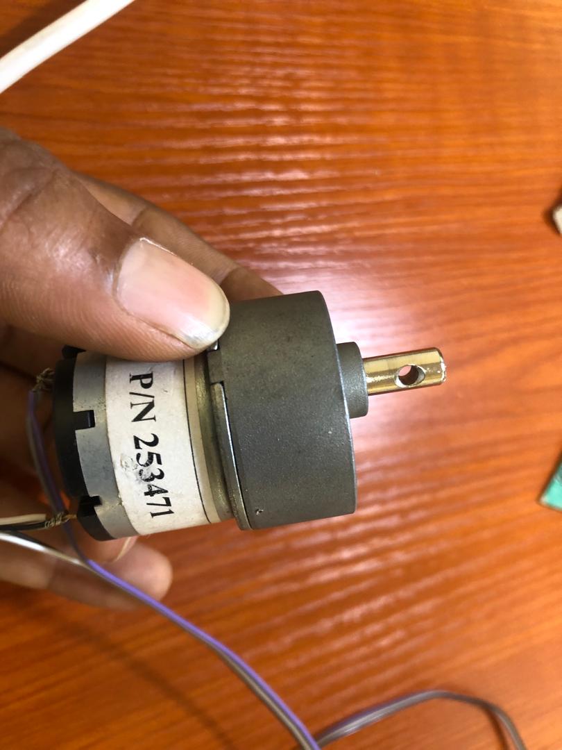
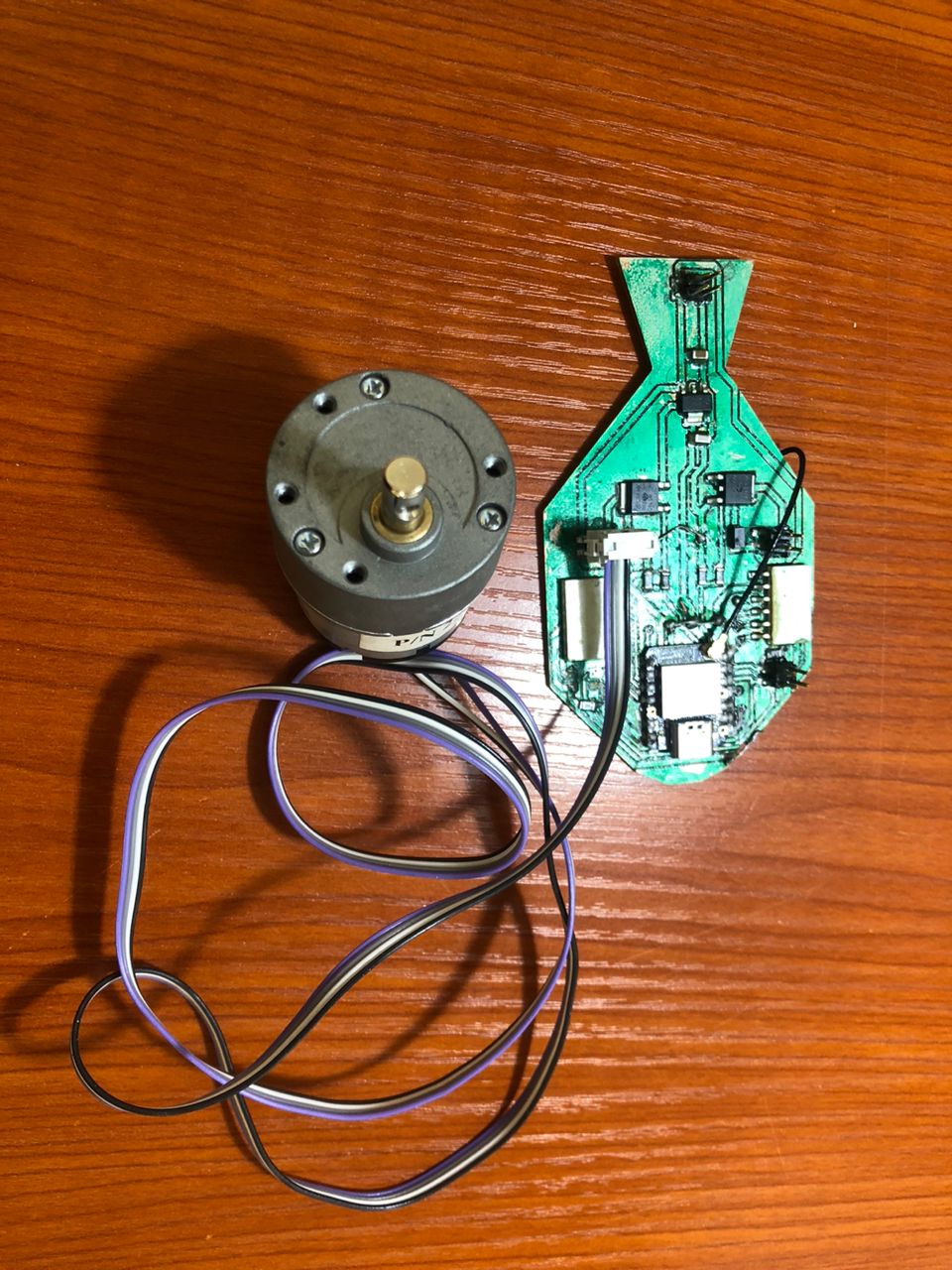
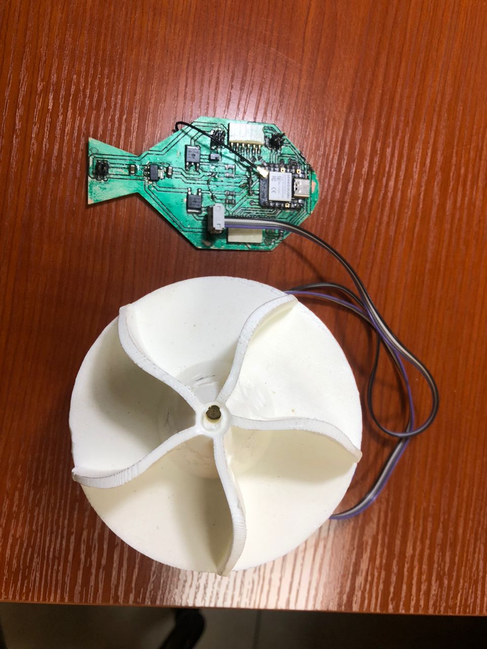
This week, I am adding a DC geared motor to my final project board I developed in week 8: Electronics Design. The motor will serve as a propelling mechanism for dispensing fish feed to my fish pond. Visit my final project page for more.
I used a mosfet ( RFD16N05LSM9A) to drive the motor in the following configuration
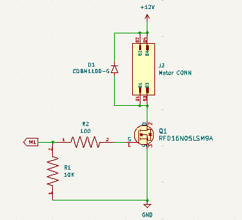
I connected the motor’s wire to an IDC connector and hooked it up to the motor driver output pins on the board.
Then I wrote the code below to test run:
const int motor = 2;


void setup() {
    pinMode(motor, OUTPUT);
}


void loop() {
    digitalWrite(motor, HIGH);
}
Output:
I have attached a propeller to the motor in order to run a speed test using Pulse Width Modulation (PMW).
I tried to use the arduino analogWrite() function to vary the speed but it failed. I had to use a specific library, ESP32-ESP32S2-AnalogWrite, by David Lloyd.
Run 50% Duty:
#include
    const byte motor = 2;
    unsigned int duty = 127;
    Pwm pwm = Pwm();


    void setup() {
    }


    void loop() {
        pwm.write(motor, duty);
    }
Output:
Run 100% Duty:
#include
    const byte motor = 2;
    unsigned int duty = 255;
    Pwm pwm = Pwm();


    void setup() {
    }


    void loop() {
        pwm.write(motor, duty);
    }
Output: